
The parametric exploration started from the structural node. A column connected to an inclined beam. Then, it was mirrored around a central axis generating an umbrella structural node. We explored multiple design expressions to arrive at the final version, the one marked with red. This structural node can be applied to a variety of given footprints: rectangular, linear, circular, single storey or multilevel.
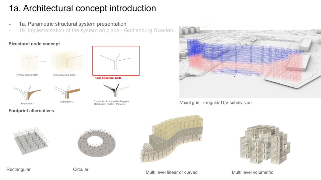
A volumetric voxel grid approach was explored and tested, but for our final design we chose to work with the linear multi story building version. The possibility to divide the U,V count irregularly, provides options that can host a wide range of programs. We decided to showcase the full potential of the parametric system, by “sculpting” the voxel grid. The result is two linear volumes connected by a bridge building
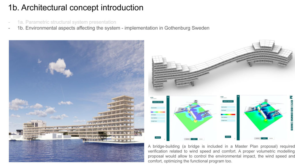
Placed in Gotheburg Sweden, the structure is strongly affected by prevailing south west winds, coming from the sea. The area is a post industrial port that currently is under development. The wind and solar analysis were considered to give shape to the volume of the building proposal. A bridge-building (a bridge is included in a Master Plan proposal) required verification related to wind speed and comfort. A proper volumetric modelling proposal would allow to control the environmental impact, the wind speed and comfort, optimizing the functional program too.
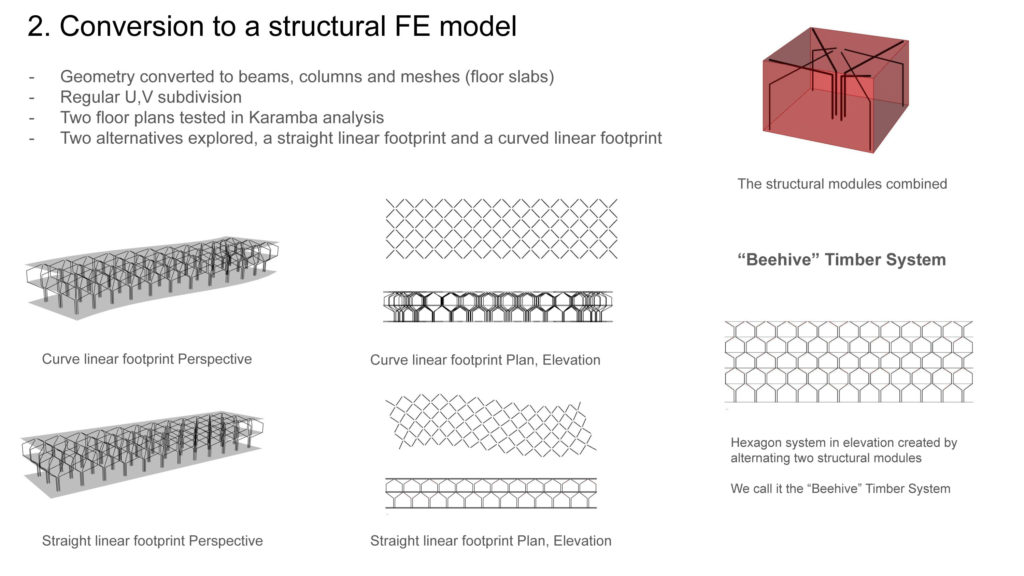
To convert the geometry to an FE Finite Elements model, we decided to simplify the Studio Project structural model in order to test better results and analyses of the simplified scheme. Our findings can then be scaled up, readapted and applied to the final shape of the system. The FE model consists of beams, columns, and floor slabs converted to meshes. U, V count is regularly divided ( all U division are equal to each other, all V division the same). Primarily, two floor plans has been tested as a minimum stage for the multi level performance. A third floor was added to one of the design explorations (next slides). We explored two alternatives, a curved footprint and a straight, linear footprint, as the most simple expression of the system. The node is divided in two expression, placed in every other floor. In that way a beam is always connected to a column. The elevation of the structure is resembling a beehive.
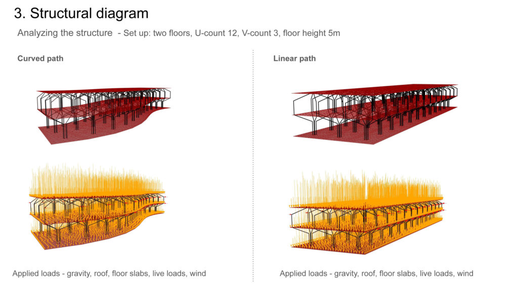
The structural diagram consists of two floors, with node type A
( umbrella ) in entrance floor and node type b (hat) in floor above. U – count is 12, V count 3, floor height 5m.
The Loads applied are the following:
-Gravity,
-Superimposed roof load
-Floor plan load
-Live load on entrance floor
-Wind load from south west, as a point load at the connections of the structure with the facade.
In this case it is the end points of the first floor columns.
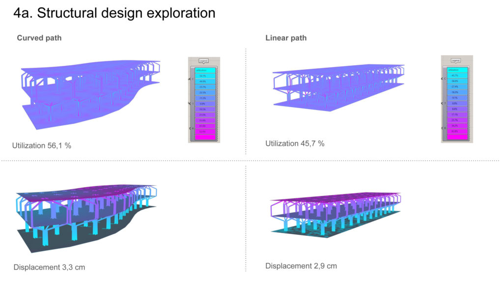
We explored the differences of the curved vs linear path. It is good to note here that both version are executed with the same GH set up, containing the optimize beam component with desired max displacement 70%. Utilization is better in the curved version whereas the displacement is smaller in the linear path version
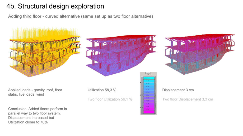
By adding a third floor to the curved alternative we realized that utilization is actually improved to 58,30%. And displacement not really affected 3 cm
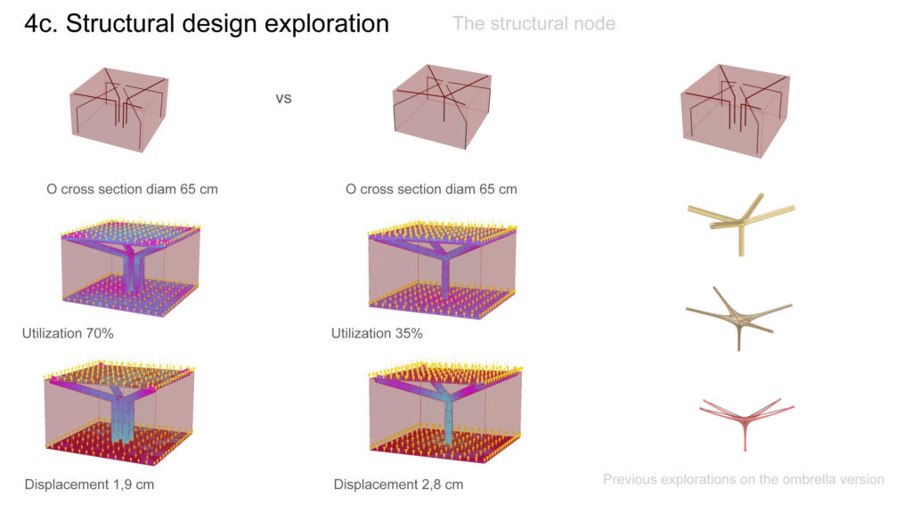
A design investigation for the structural node was necessary to select which option works better from a structural perspective. Even though the “Four Columns” version uses more material, both the Utilization and the Displacement are better for the same cross section of 65 cm in diameter. This alternative allows more design freedom, since facade elements, space separators or technical elements can be placed in the intersection space. Moreover the Four Columns version allows the adaptation to non standard planimetric modules.
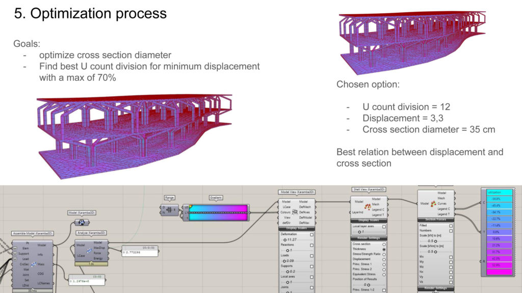
Our intention was to minimize the displacement by alternating the u count, which controls how many subdivision we have in the long side of the building. The best solution is clearly the one that has 12 u count divisions. Displacement is quite little, cross section elegant 35 cm diameter. In most other outcomes either the cross section was extending the 50 cm which has an impact in both utilization and design.
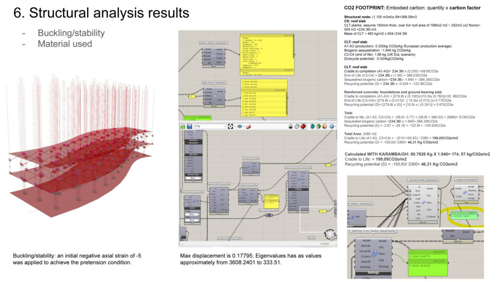
The tests included also buckling analysis for a Z load of (-5 and -100).
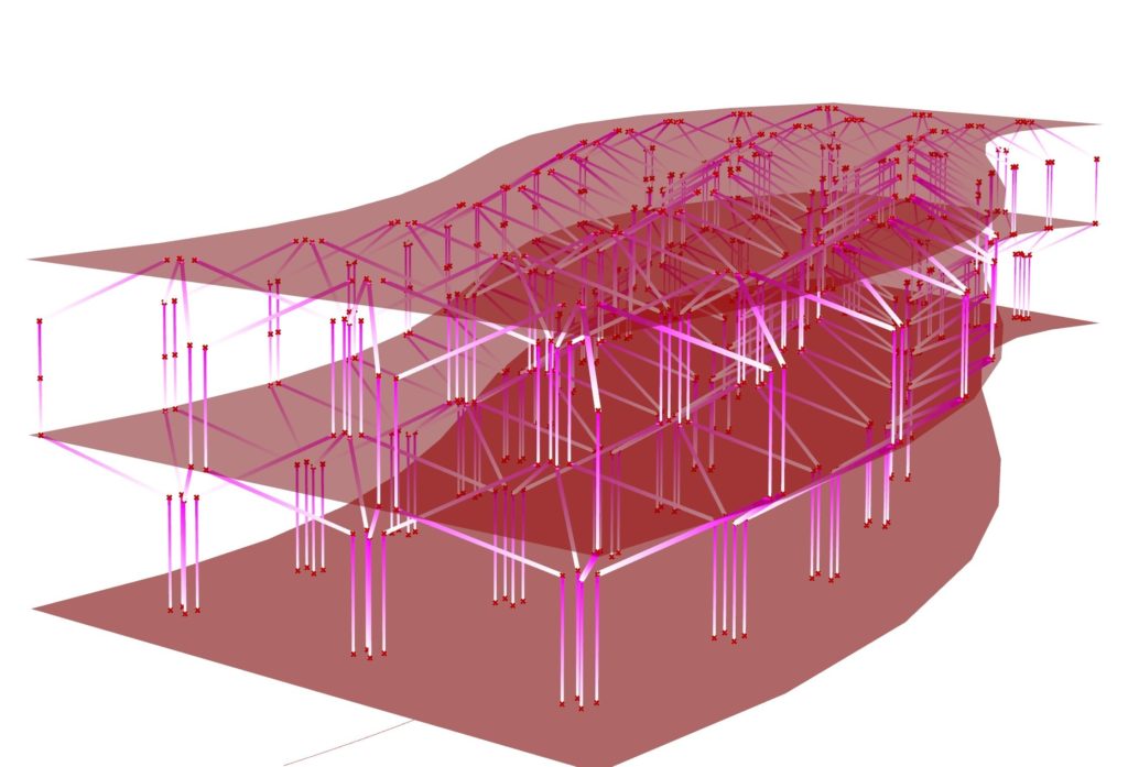
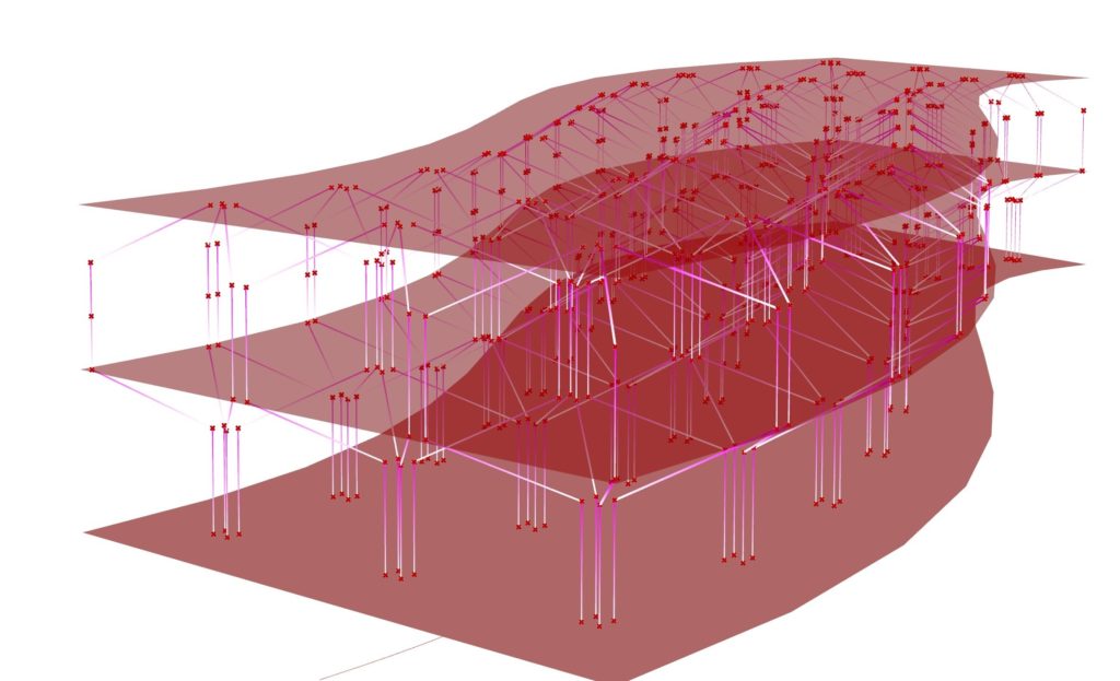
Buckling analysis has been applied both to columns and beams, or better to the combination of column+beams. Buckling/stability: an initial negative axial strain of -5 was applied to achieve the pretension condition.
Max displacement is 0.17795; Eigenvalues component has as values approximately from 3608.2401 to 333.51.
An error occurred while introducing wood as material in the Karramba Script:. “The structural system buckles under the given loads in 4 modes. Reduce the compressive normal forces. Displacement increments did not converge: The Euclidean norm of the difference of the nodal displacements for the last two iterations was 0.74889512583874[m]. The target tolerance is 1E-07[m].”. After untroducing -5 as normal force the Displacement arrived to 1.514077. The Material used has been verified with two methods, one with Karamba.
As a conclusion we understand from the analysis that the system is suitable, and represent a reliable base to refine and improve the structural analysis for multi level timber construction, and has a flexibility in shape and performance
