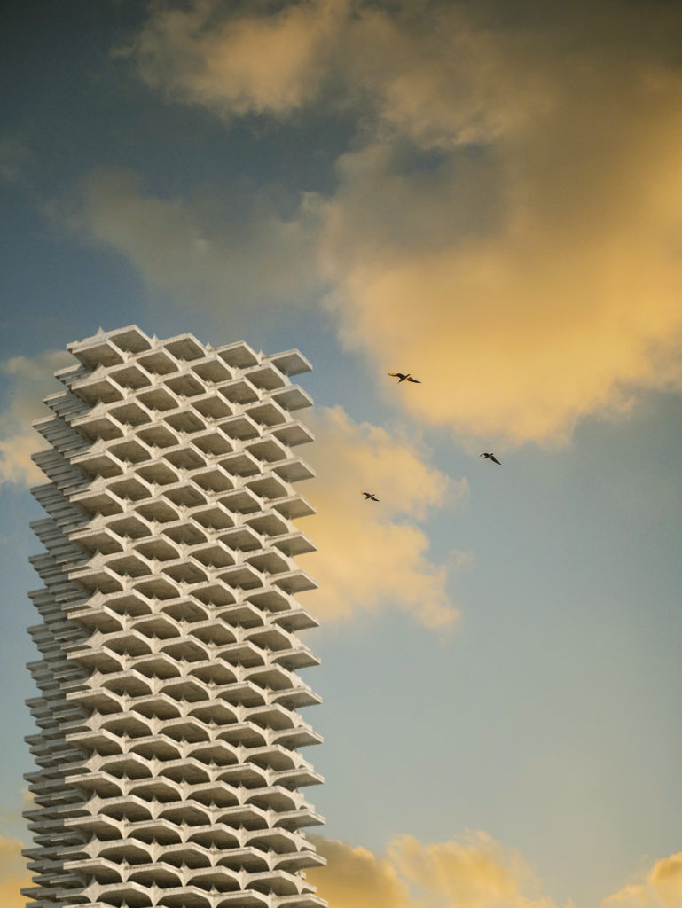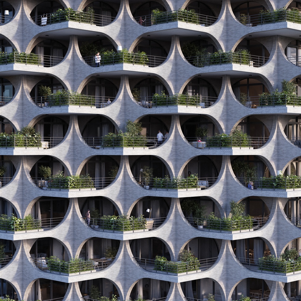
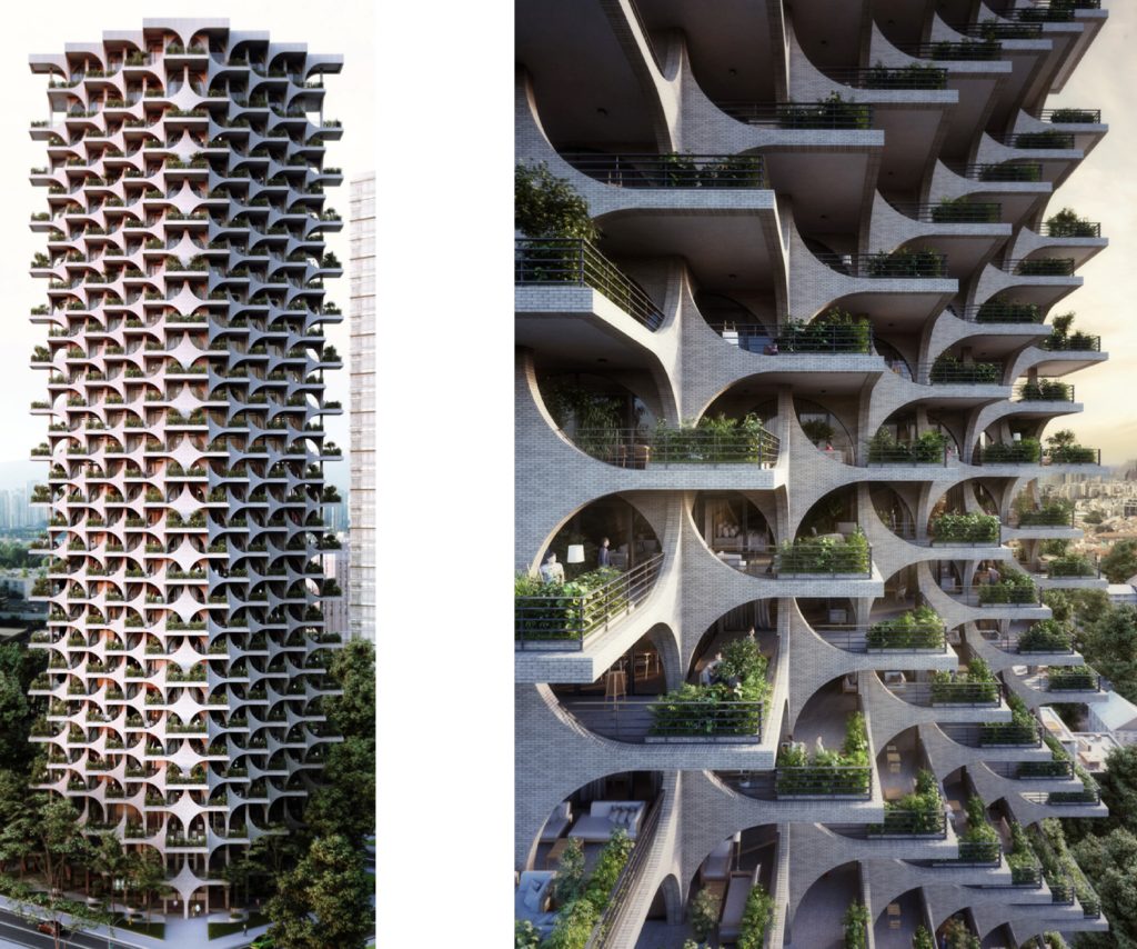
Penda is a high-rise residential tower in Tel Aviv, featuring brick arches and cascading terraces influenced by the city’s Bauhaus era and the materiality of its Old Town. The 116 meter high scheme will house a range of one to four bedroom apartments, as well as double-height penthouses. The tower is designed in a modular system, allowing structural elements to be prefabricated at lower construction and maintenance costs. The geometry of the building has been heavily influenced by the Bauhaus, with its emphasis on openness, clarity, and rationality exhibited in the clear design language of the arches and lines. The 17,500 square meter scheme is defined by its cascading arches, chosen for its historical “shelter” roots in architecture, and its traditional role as a “welcoming gesture” at the entrance to buildings and cities. Together with layered terraces, the rhythmic layout of the arched structure creates a façade which reflects the vividness of Tel Aviv striking a balance between openness and shelter.
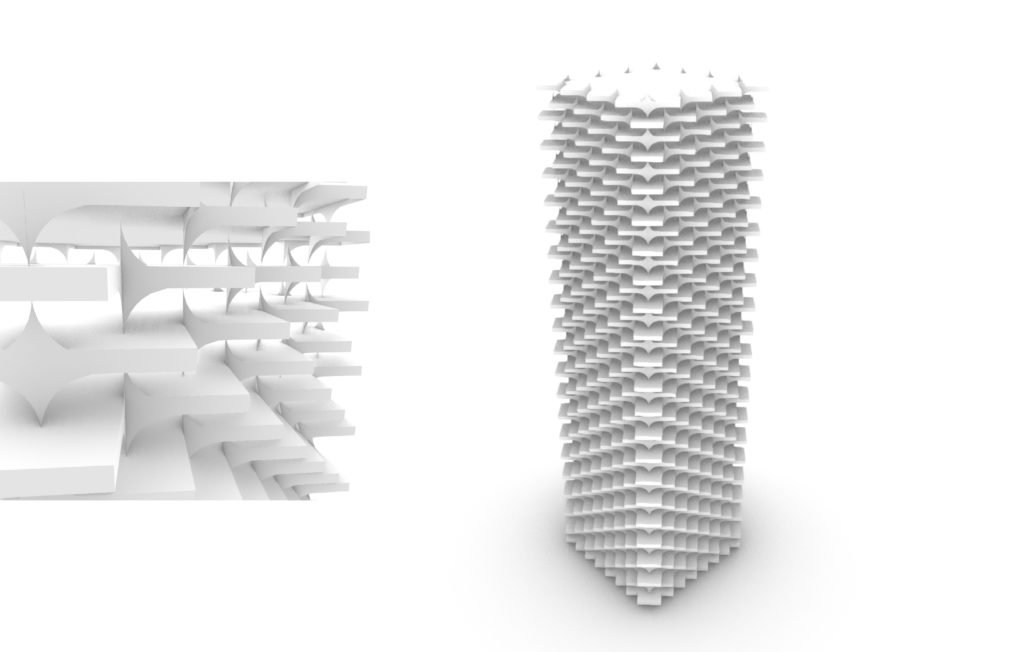
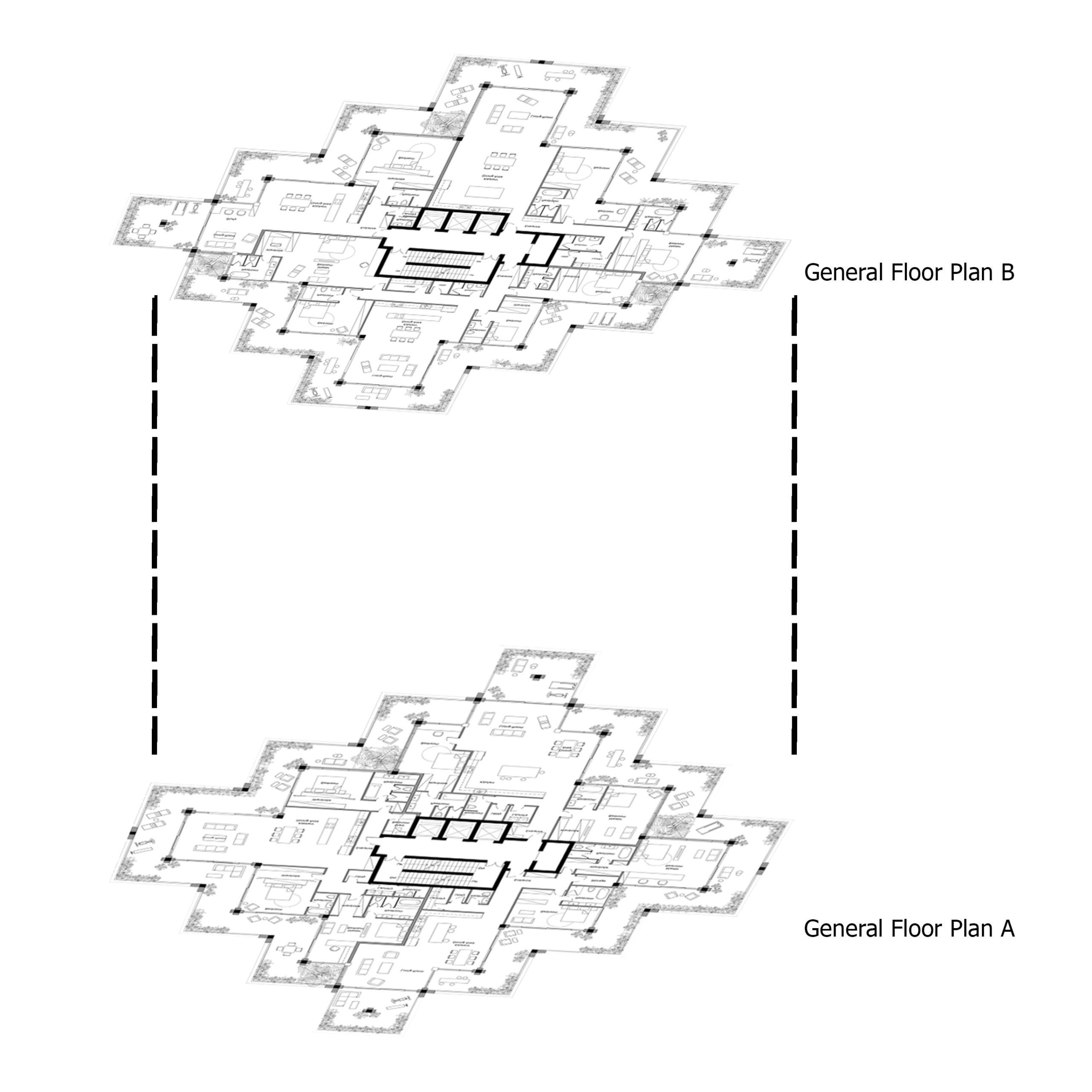
Deconstruction Logic
The main logic to achieve the form was to analyze the planning. It was simplified in a rotation of two typical and basic plans which made the whole vertical form. So, getting to the parametric facade has been done through making the plans.
Code Explanation and Process
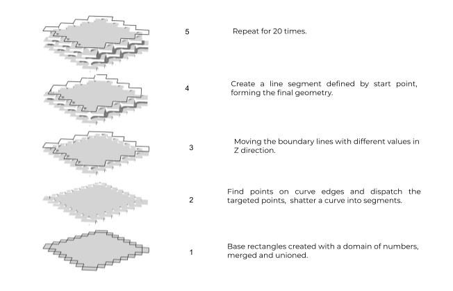
- Create a rectangle on a plane by using the numeric domain command, which the end value of it is the negative value of the starting value.
- With this strategy it is created four rectangles.
- Merge the the four data values with Merge component and use Region Union component to union of a set of planar closed curves.
- Use the Discontinuity component to find all discontinuities along the curve.
- Dispatch the items in a list into two target lists and Shatter a curve into segments.
- Divide curves on two lists with Dispatch component two separate the two different types of geometry.
- Move the curves along Z vector and use SDL Line to create a line segment defined by start point.
- Shutter the same group of curves into segments and use Fillet component to join these two group of curves.
- Repeat the same process for the creation of the negative form of the geometry.
- Shutter and Parameterized both groups of curves.
- Use the List item component to retrieve the curves from the list.
- Create lofted surfaces from the two groups of curves.
- Use Series and Move component to create the final geometry.