Over the past three weeks, we took the Digital Fabrication introductory course through which we developed a foundational understanding of production techniques such as 3D printing, CNC milling, and laser cutting.
In each section, we explored the capabilities and limitations of the manufacturing processes through test prototypes before finalizing the geometries.
3D PRINT_Angle Slicing
In the 3D printing section, we explored the relationship between layer thickness and overhang angle. A thicker layer would allow for a faster print time, yet a weakened ability to maintain an angled wall. Our goal was to optimize both print time, angle, and height.
Test Prints
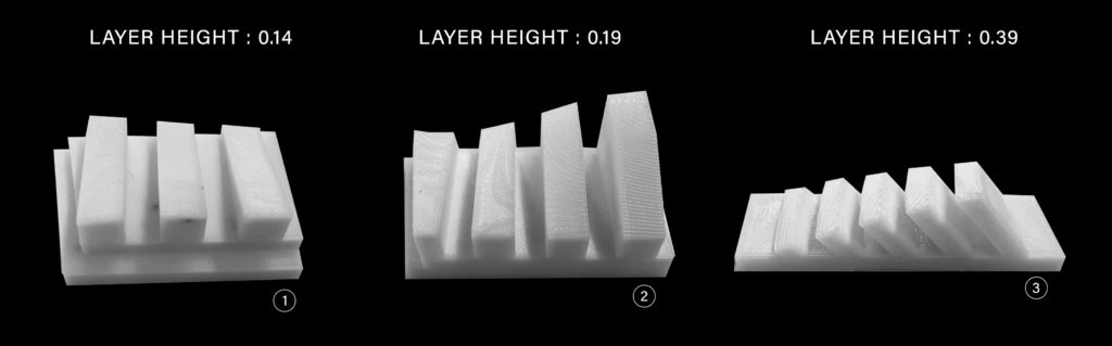
Test prints 1 and 2 explore varying heights and layer thicknesses of 0.14mm and 0.19mm respectively. The wall angles remain at 90 degrees, reducing risk of collapse.
Test print 3 combines an increased layer thickness of 0.39mm and angled wall that is less than 45 degrees, but more than 15 degrees.
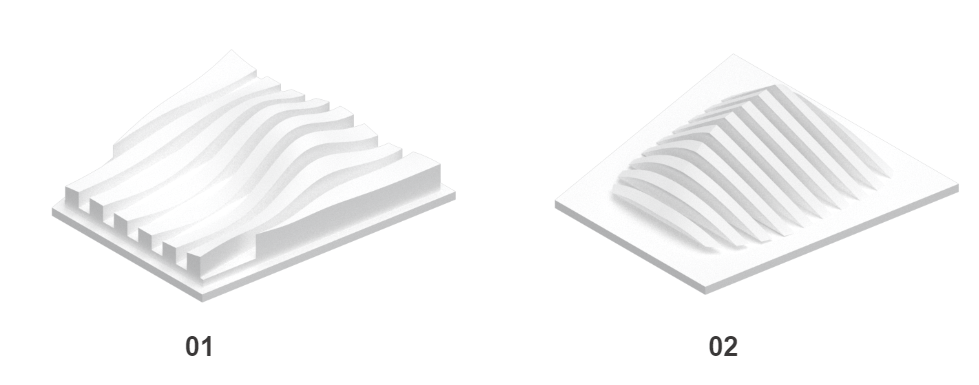
Final Geometry

The final model was printed at 0.19mm with an angle <45 degrees, and >15 degrees.
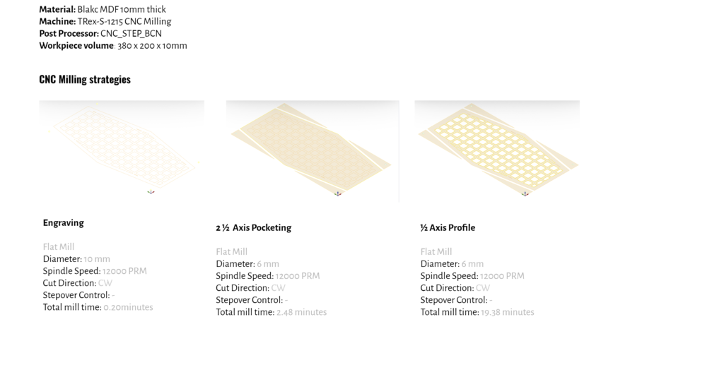
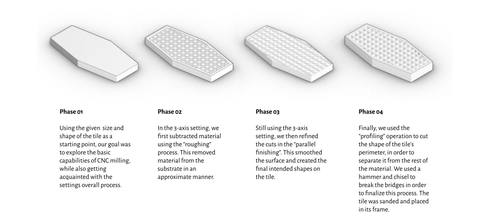
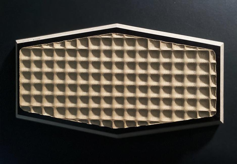
CNC Milling_Smoothing
In this section, we explored various CNC machining processes using Rhino Cam software. Understanding the different stages of milling allowed us to achieve a particular desired texture and geometry, while of course considering fabrication time.
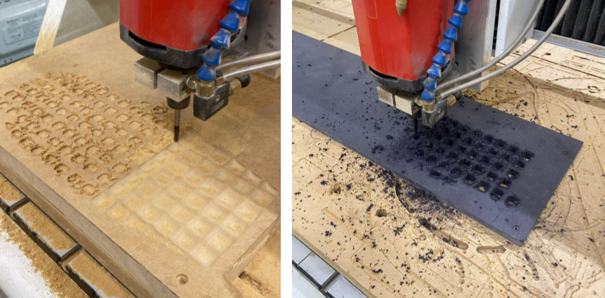
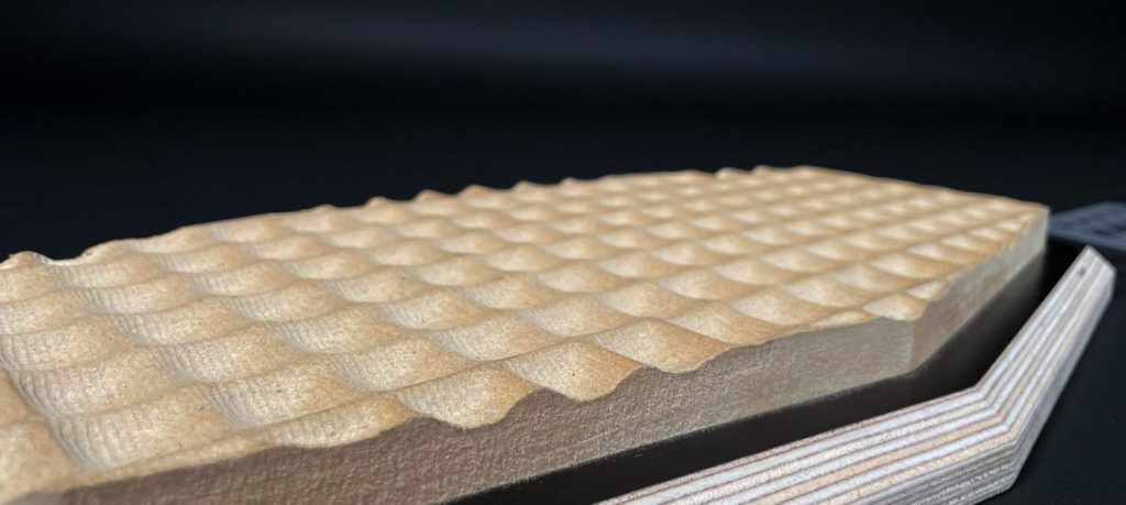
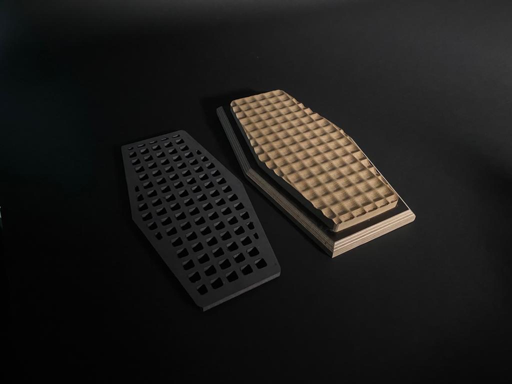
Milling Test
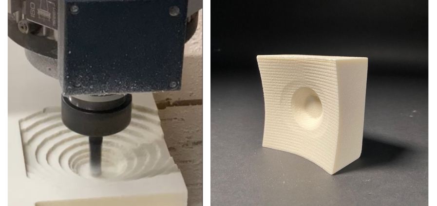
In this test geometry, we explored the basics of roughing and parallel cutting. Roughing was used to cut a “raw” version of the shape, while parallel finishing was used to soften the surface.


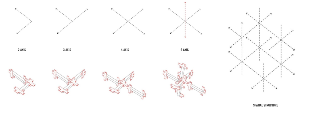
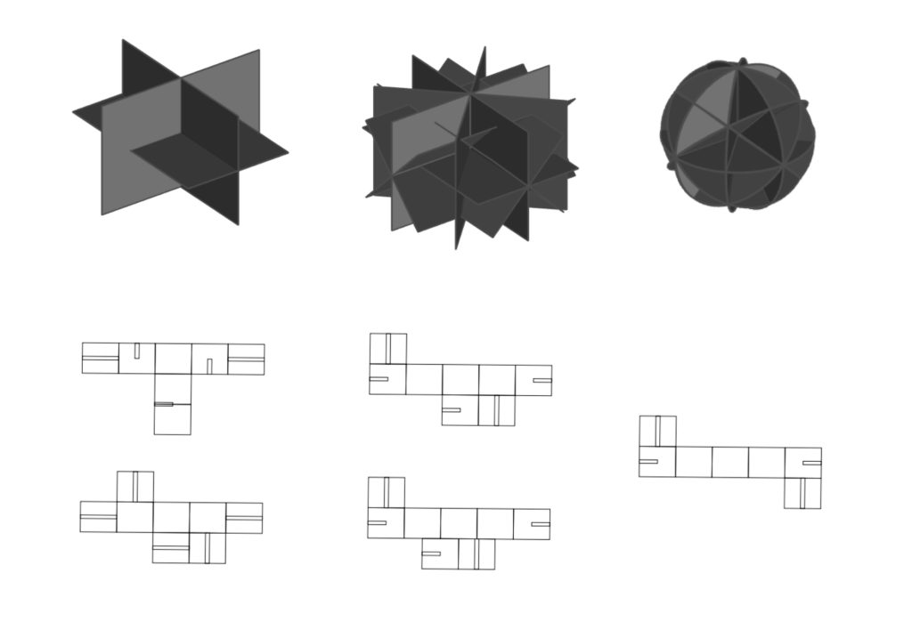
Laser Cutting_Interlocking
In this section, we were prompted to design an interlocking spatial joint for 35x35mm timber beams using laser cutting techniques.
Test Joint
Concept and Reference
‘Chidori’ traditional Japanese joint
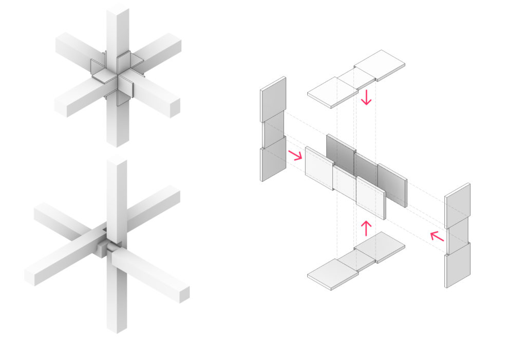
Final Geometry
Concept and Reference
Aims:
- A single module in repetition
- A flexible system that can be configured in different ways
- Possibility to separate and endlessly recombine the elements
- Possibility to expand or reduce the scale or number of arms the final composition has.

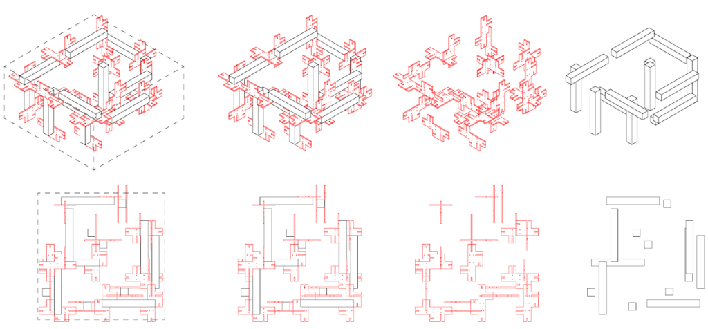
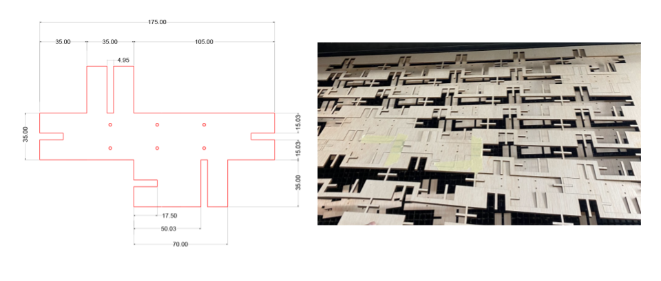
Design Process
Time and machine preparation
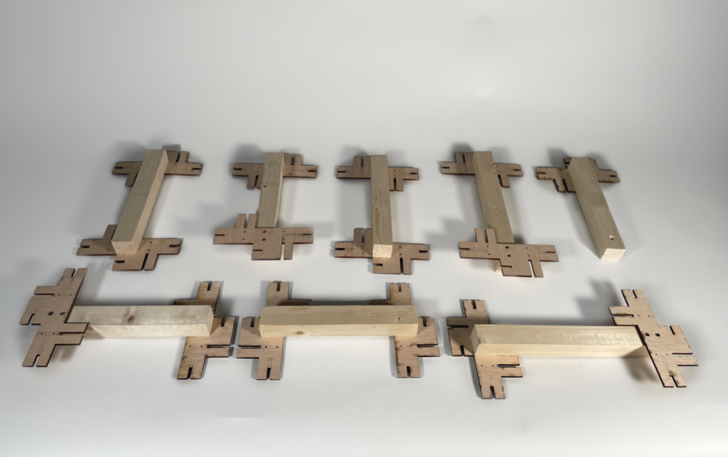
Material: Plywood 4.95mm
Technique: Laser Cutting
Joint type: Interlocking
Machine: Rayjet 500 laser cut
Working Parameters: Power 50 Speed: 1.7
Allotted Cutting time: 2h
Cutting time: 1.3h
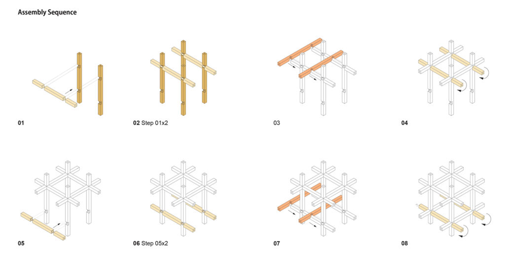
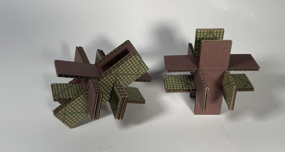
Final Module
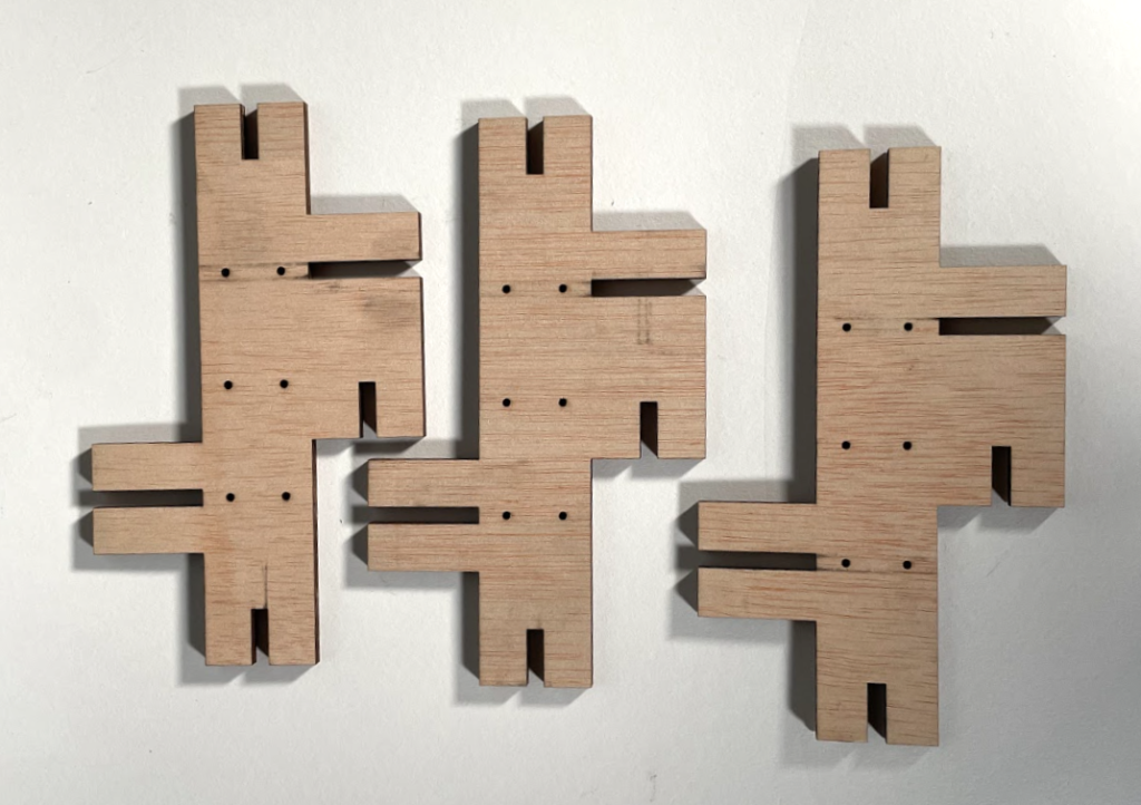
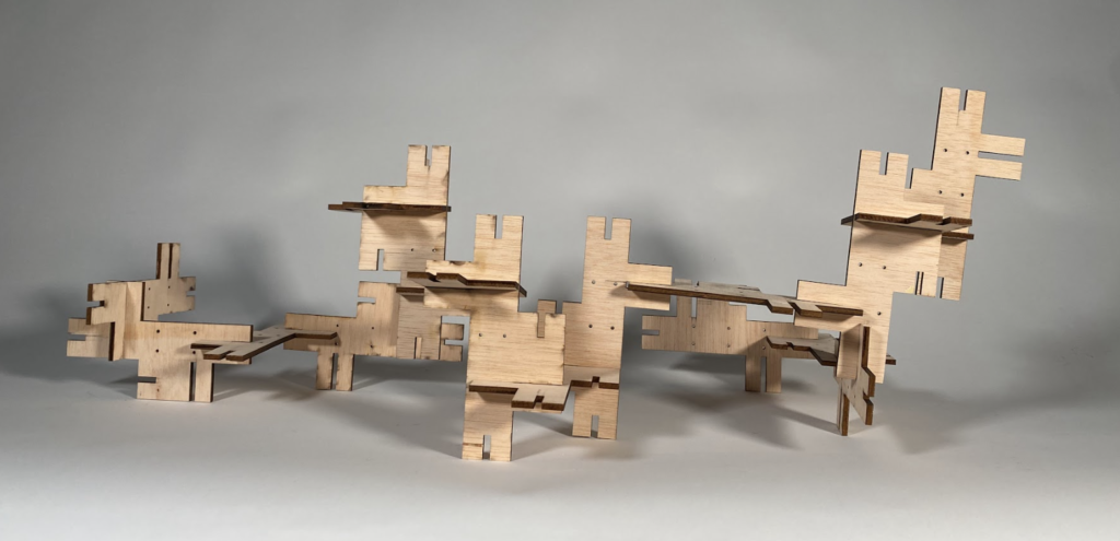
Assembly

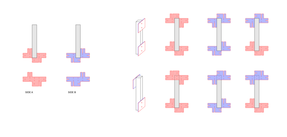
Final Structure