Digital Fabrication is an introductory 3-week course on new production techniques through the relationship between computer data and machine-oriented fabrication. The course aims to explore the design opportunities arising from three common digital fabrication processes: laser cutting, CNC milling, and 3D printing.
Laser cutting_spatial joints
This exercise aimed to join recycled timber beams into informed and complex spatial structures that follow a specific constructive assembly logic ruled by spatial joints created by bending the material.
Concept_flexibility
“The beauty of the project lies in deciding when to abandon precision
and begin to react intuitively.”
Even though computer-aided manufacturing and robotics have given architects unprecedented control over the materialization of their designs, the nuance and subtlety commonly found in traditional craft practices are absent from the artifacts of robotic production. Nobody can surpass human intuition and their understanding of the qualitative aspects of a project. Hence, our idea was to produce a spatial joint that does not have to be prefabricated. Through this approach, spatial joints can be intuitively changed and altered on the site.
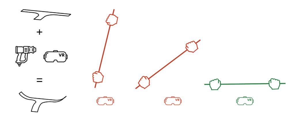
By rendering digital models as holographic overlays directly within construction environments, fabricators can use their expertise and inventiveness to produce highly intricate and complex objects entirely by following these holographic guides using relatively primitive analog tools. On the site, workers would receive VR headsets, which would display in front of them the required angle lines. Afterward, they would use the heat gun to reach the required temperature and bend the joints.
Process
Through the research of the material properties, we concluded that acrylic fulfills all the properties needed for achieving the objective. It is a thermoplastic that becomes pliable and moldable at 160°C so it can receive any angle deformation. We pushed the limits of bending possibilities in order to conduct a research on durability.
machine: rayjet 400
speed: 1.5
power: 60
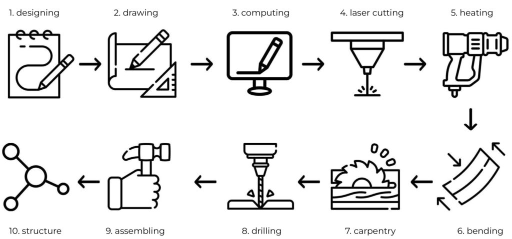
The first step was to design a spatial joint with at least three connection points. Afterward, we converted the joint into a 2d drawing in Rhino, put the file in the software, and set the machine for laser cutting by placing the acrylic in position. After the pieces were cut, we used the heat gun to bend parts of the acrylic to achieve the bending. To connect two or more joints and assemble the structure, we used 20mm diameter timber members, fixed the spatial joints in the slits created, and fixed it with wooden dowels, thus achieving the desired assembly.
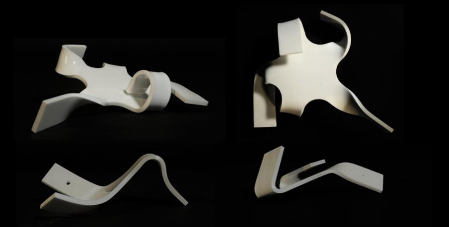
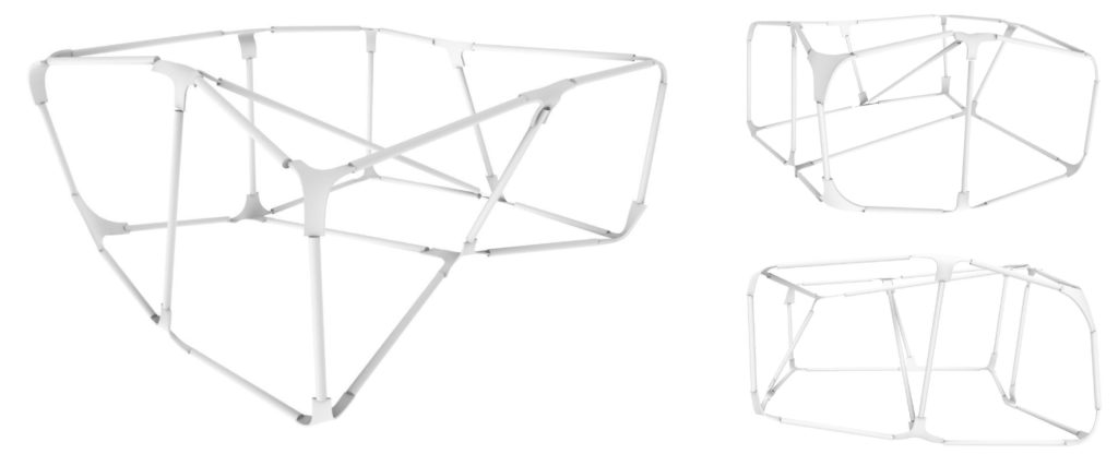
Workpiece
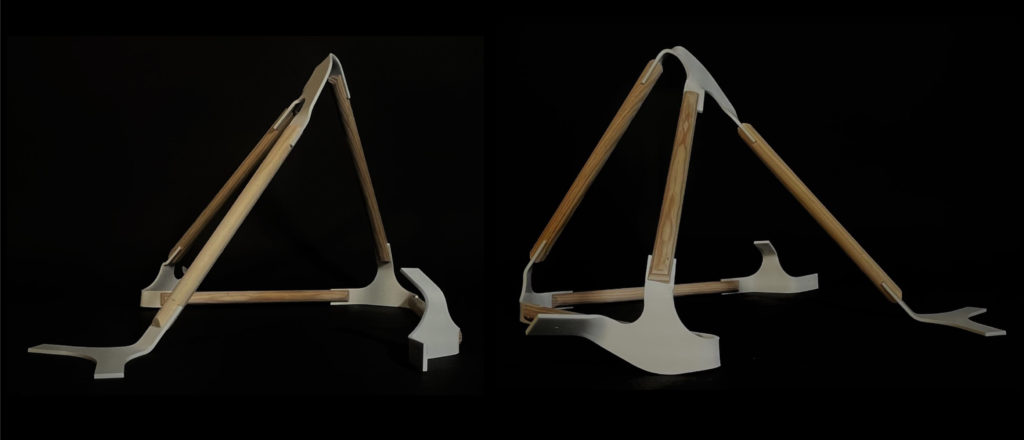
While producing the spatial joint, we had been also working on the expanding of the spatial structure. Through the software we created a structure of sticks bent in different angles and directions.
3D printing_shading devices
The goal of the exercise was to design a facade with a 3D printing technique taking into consideration the transparency, allowance of light through the facade, and the facade shading.
Concept_translucency
“The advancement in computation technology and alternative materials
changes the way architects think about facade designs where technology is driven by solar control
wherein the idea is to maximize natural daylight without glare and excessive heat gain.”
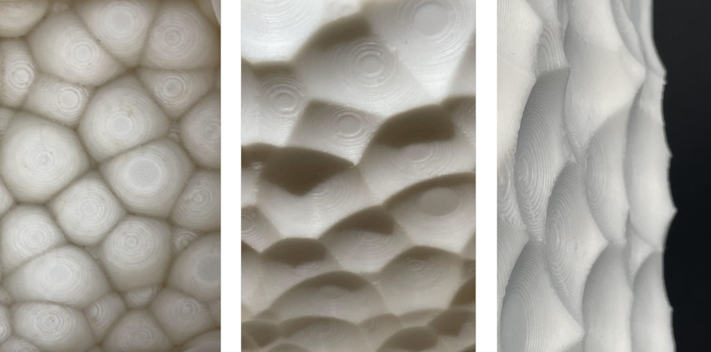
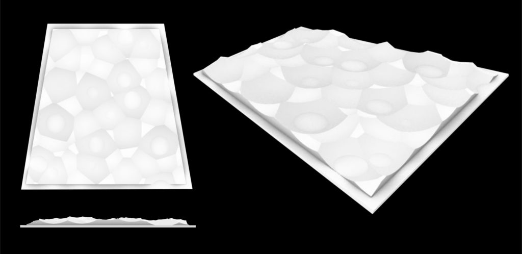
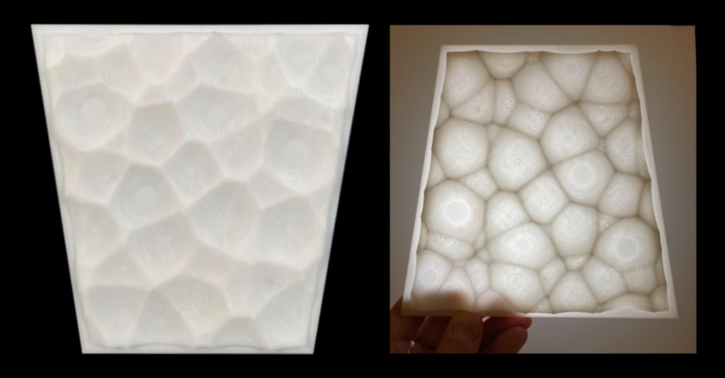
The design is a derivation of biomimicry of a micro zoom of a texture of a leaf. Each unit can have openings on the facade, and the material thickness is less so that the facade is translucent and gives a stimulating effect when lit up. The desired results were achieved by playing with the edges of the shapes and trying to create inverse bubbles out of them.
Process
Printer: Zortrax M200
Support Angle: 20°
Material: Z-ABS
Nozzle Diameter: 0.4mm
Layer: 0.19mm
Infill: Square 20%
Printing time: 7h22m
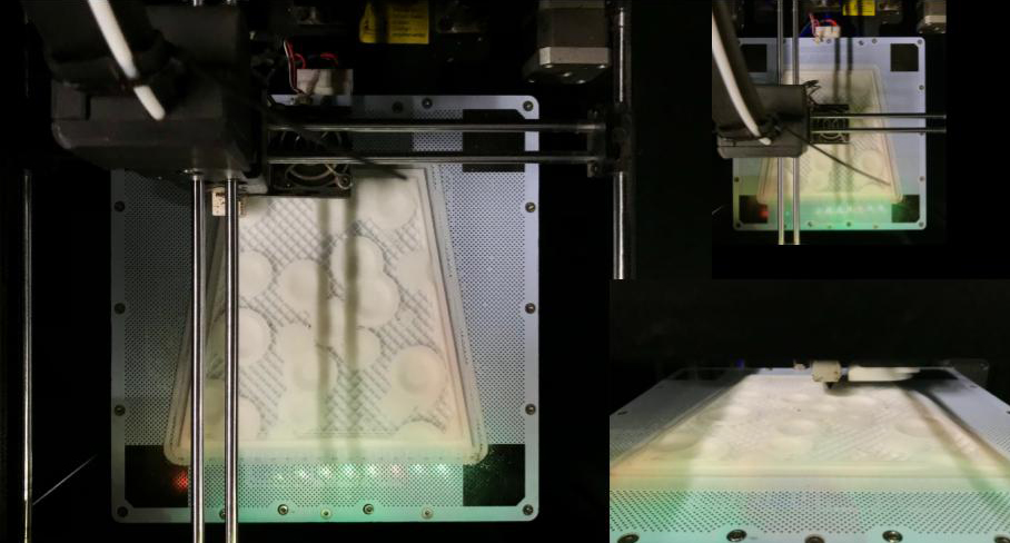
Workpiece
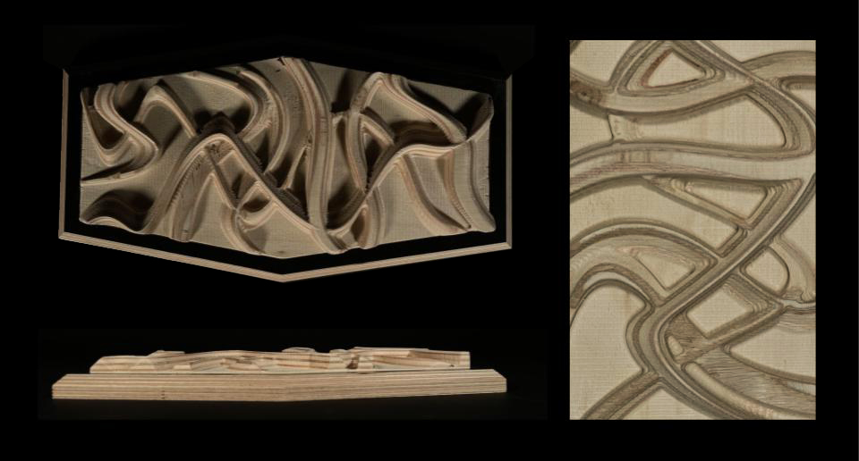
CNC milling_facade design
The goal of the exercise was to design a facade with 3d printing technique taking into consideration the shading on the facade.
Concept_curvlinearity
“The ability of curvilinear architecture to be fluidic and influenced by nature
allows them to blend with the free form of landscape.”
The design is an abstraction from intertwined roots, creating an intersection of embossed curves. Throughout this process we explored curvilinearity on a facade. These curves then create pockets that can have fenestrations, and the solid curves create shadows in the pockets.
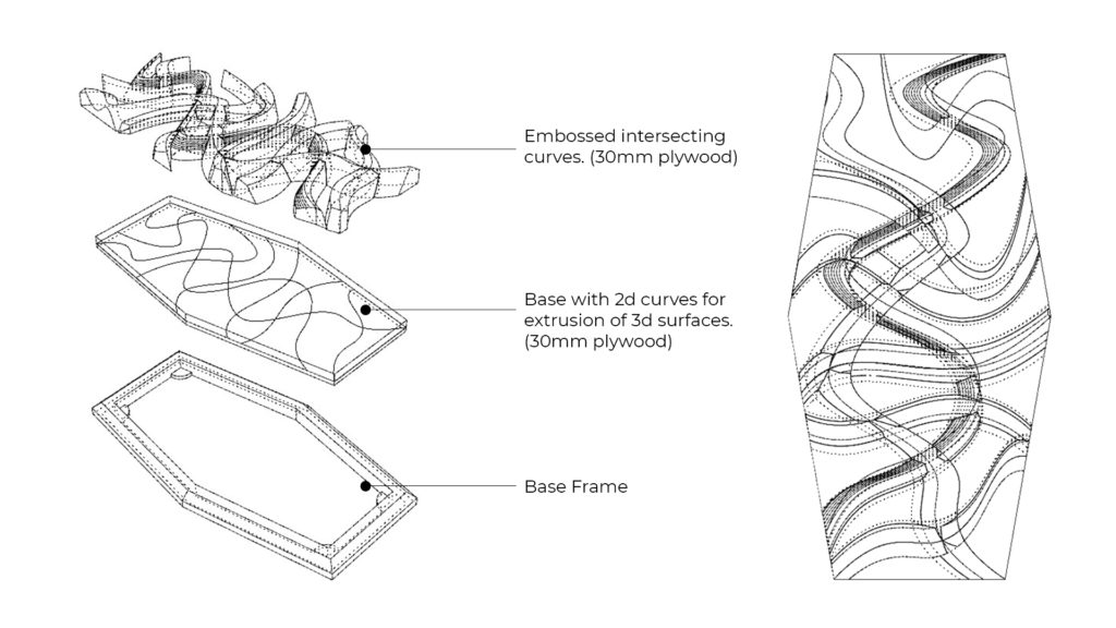
Process
Material: 30mm thick Plywood
Machine: CNC_STEP_BCN
Porst Processor: CNC_STEP_BCN
Workpiece volume: 180mm x 360mm x 30mm
Horizontal Roughing
Flat Mill
Flute: 2
Diameter: 10mm
Spindle Speed: 12000
Cut Direction: upcut
Step Down Control (dZ): 50%
Stepover Distance: 75%
Total mill time: 8.07 minutes
Horizontal Finishing
Ball Mill
Diameter: 6mm
Spindle Speed: 12000
Cut Direction: upcut
Step Down Control (dZ): 25%
Total mill time: 18.40 minutes
Parallel Finishing
Ball Mill
Diameter: 6mm
Spindle Speed: 12000
Cut Direction: mixed
Stepover Control: 25%
Total mill time: 22.41 minutes
Workpiece