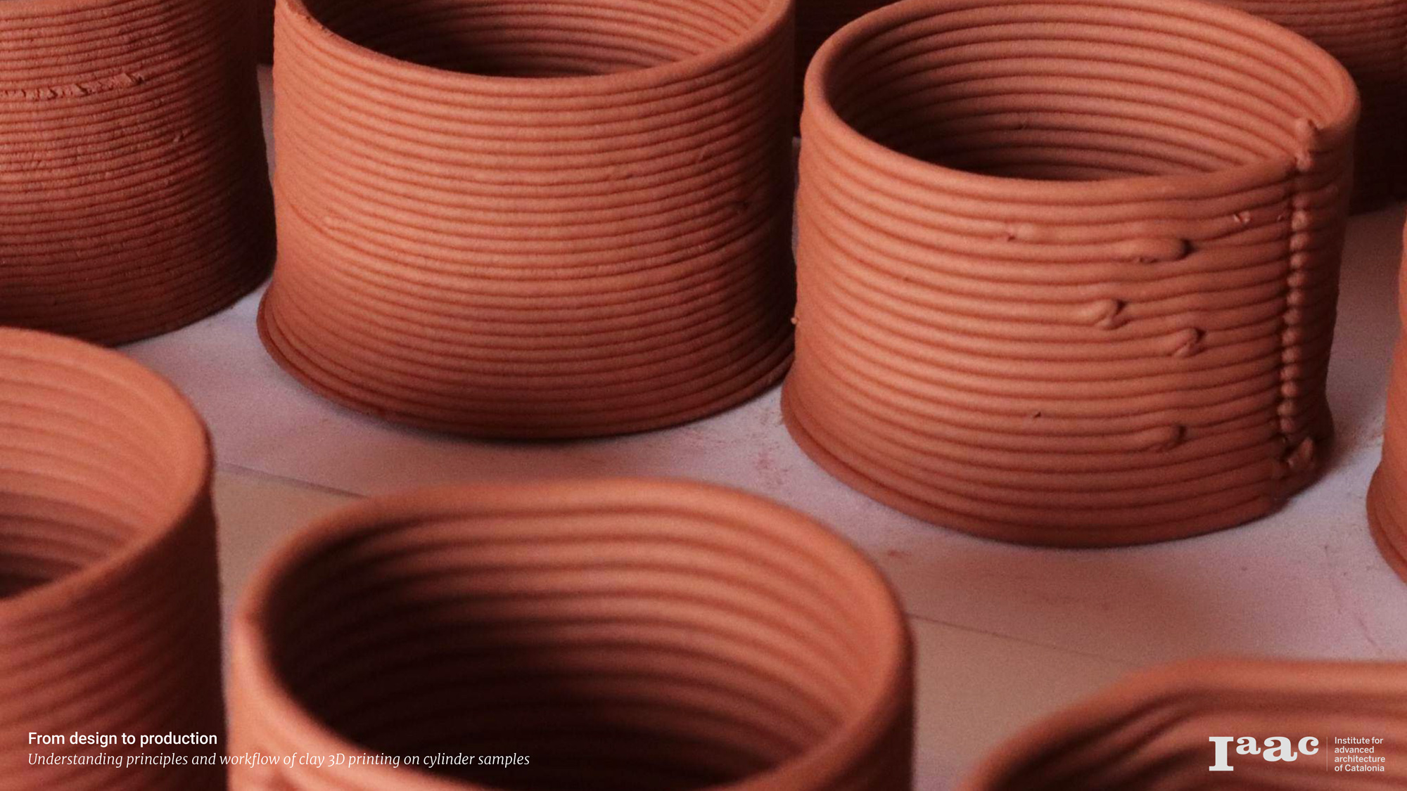
Kinetic explorations of the machine over a primary geometry in order to understand the principles and workflow of clay 3D printing on cylinder samples.
Machine was an introductory workshop to introduce technologies, techniques, and materiality on deposition modeling and its implication in the design.
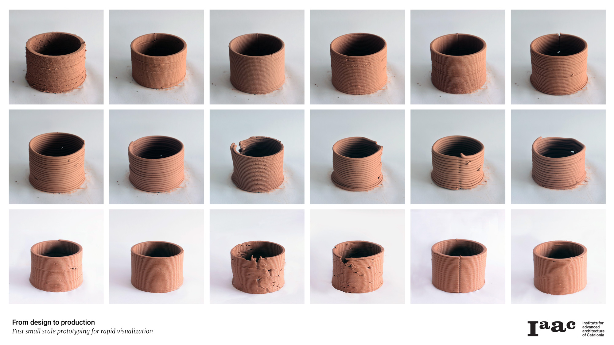
With the setup of a standard form that could return in various shapes, research groups experiment with different parameters of the material itself or the machine. The result is a matrix of primary geometries with different characteristics from which could be extracted machine parameters and setup conclusions.
_____________________
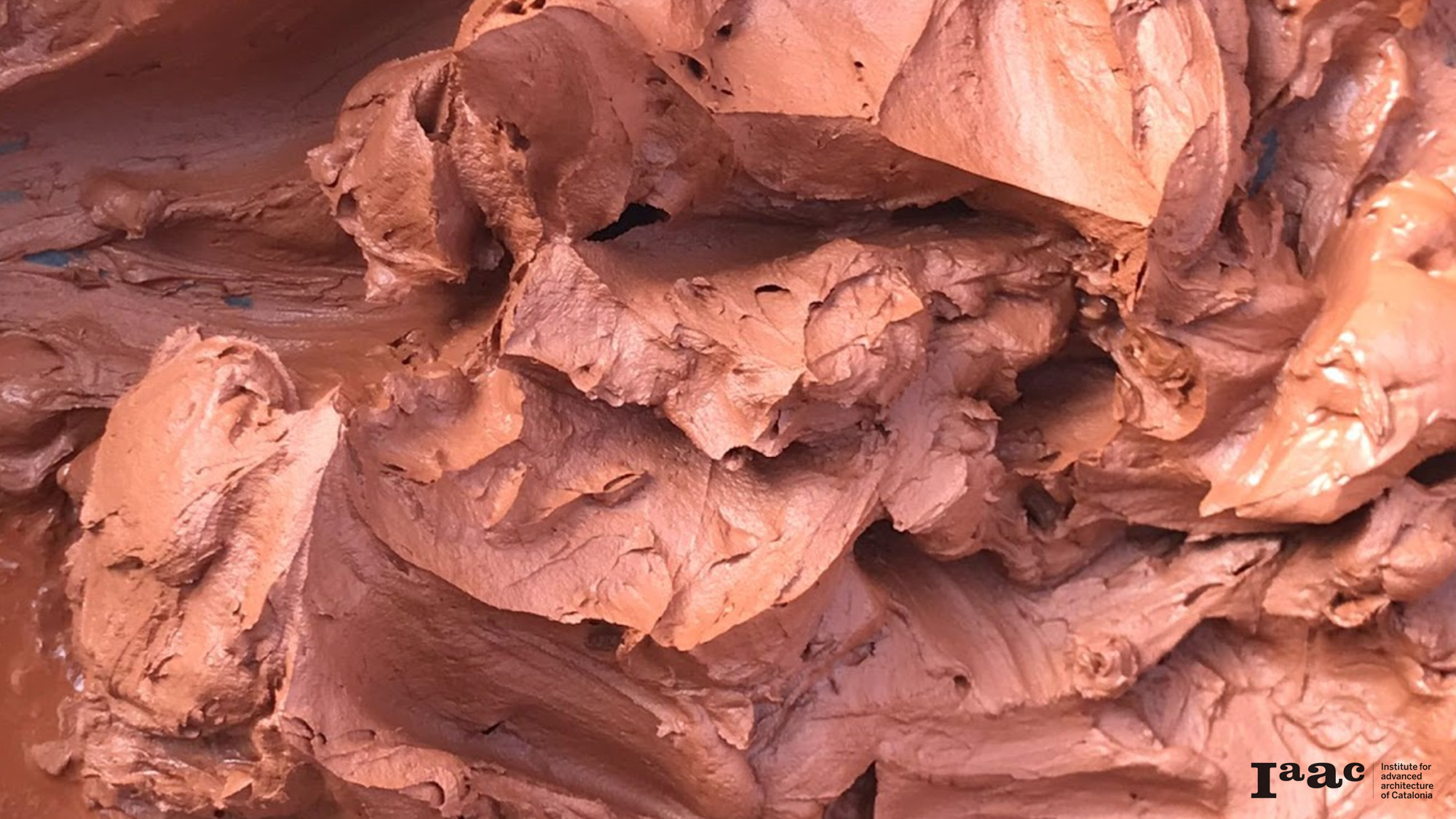
The material
Viscous enough, it needed to reach its perfect plastic state in order to be extruded – exploration was designed using only clay. The tactile sense was an important decisional factor in creating the ideal paste made of clay powder and water.
_____________________
The parametric explorations
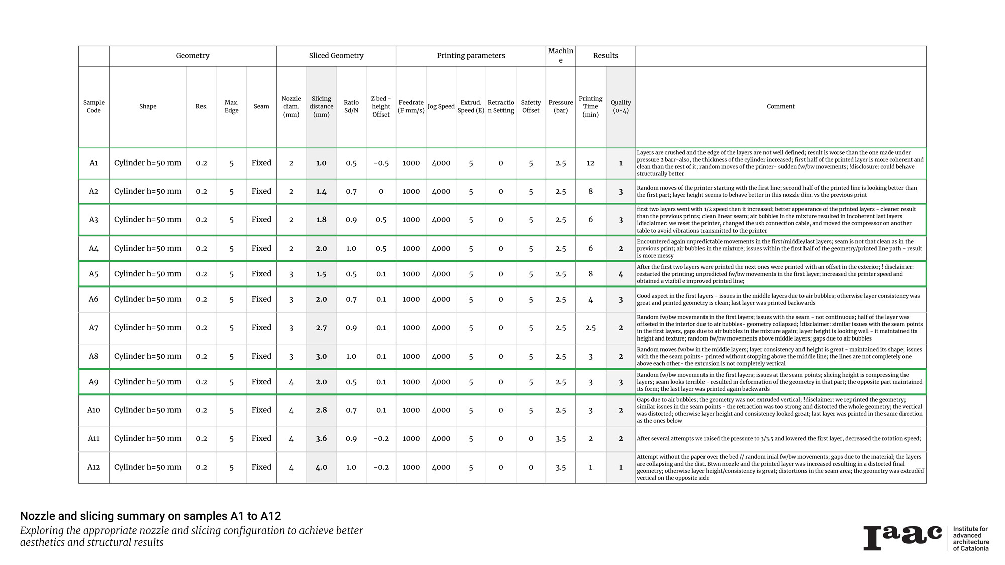
The aim of the experiment was to achieve aesthetics and structural results in a small sample (Cylinder h=50mm, diam. 70mm) that could be iterated in large-scale production. Focusing on this target, we adjusted the following parameters that will be exemplified below.
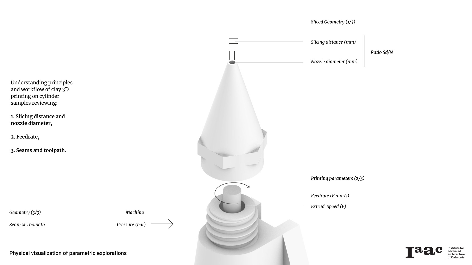
1. Slicing distance and nozzle diameter
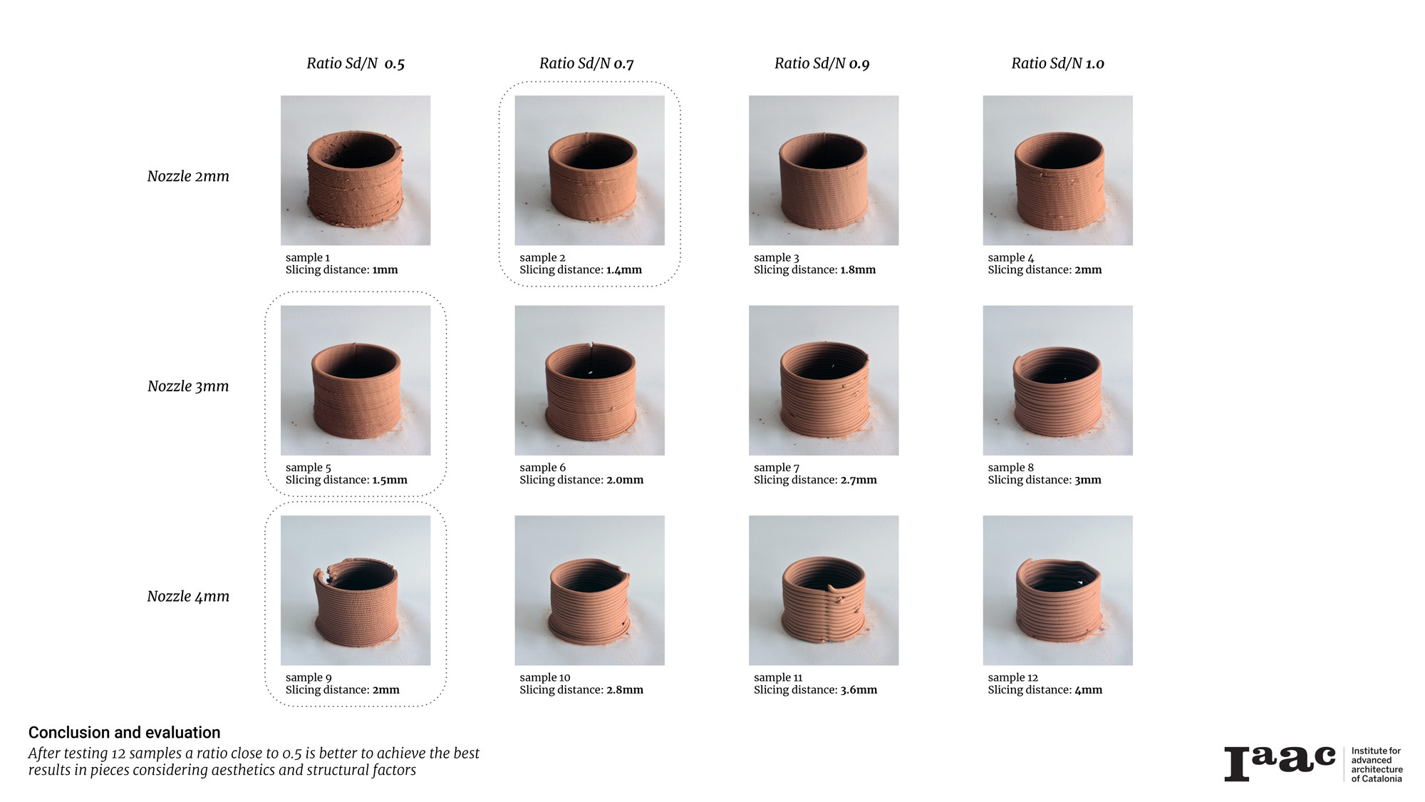
Setting up the machine with only the following nozzle diameters (N) ?2 / 3 / 4mm led us to define a ratio between them and the slicing distances (Sd) and explore its questionable similarity and applicability in a larger scale prototyping. Thus, for a more optimized conclusion, the sliced geometry was defined by a ratio (Sd/N) of ca. 0.5 / 0.7 / 0.9 / 1.0 for every nozzle diameter available – resulting in various slicing distances, always maintaining the rest of the parameters at the same rates.
Example of printing parameters:
- Feedrate (F mm/s): 1000
- Jog Speed: 4000
- Extruding Speed (E): 5
- Retraction Setting: 0
- Safety Offset: 5
- Pressure (Bar): 2.5
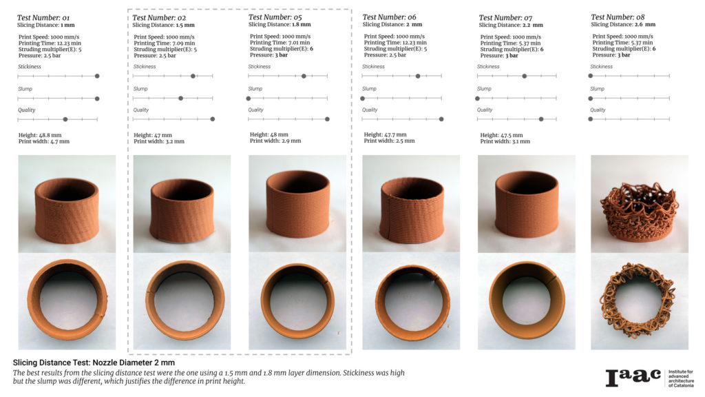
After printing multiple samples, the evaluated 3D printed clay iterations drove to the conclusion that a ratio close to 0.5 is better to achieve the best results in pieces. This conclusion was made considering aesthetics and structural factors such as lesser cracks in the extruded material, or thicker connection between the layers.
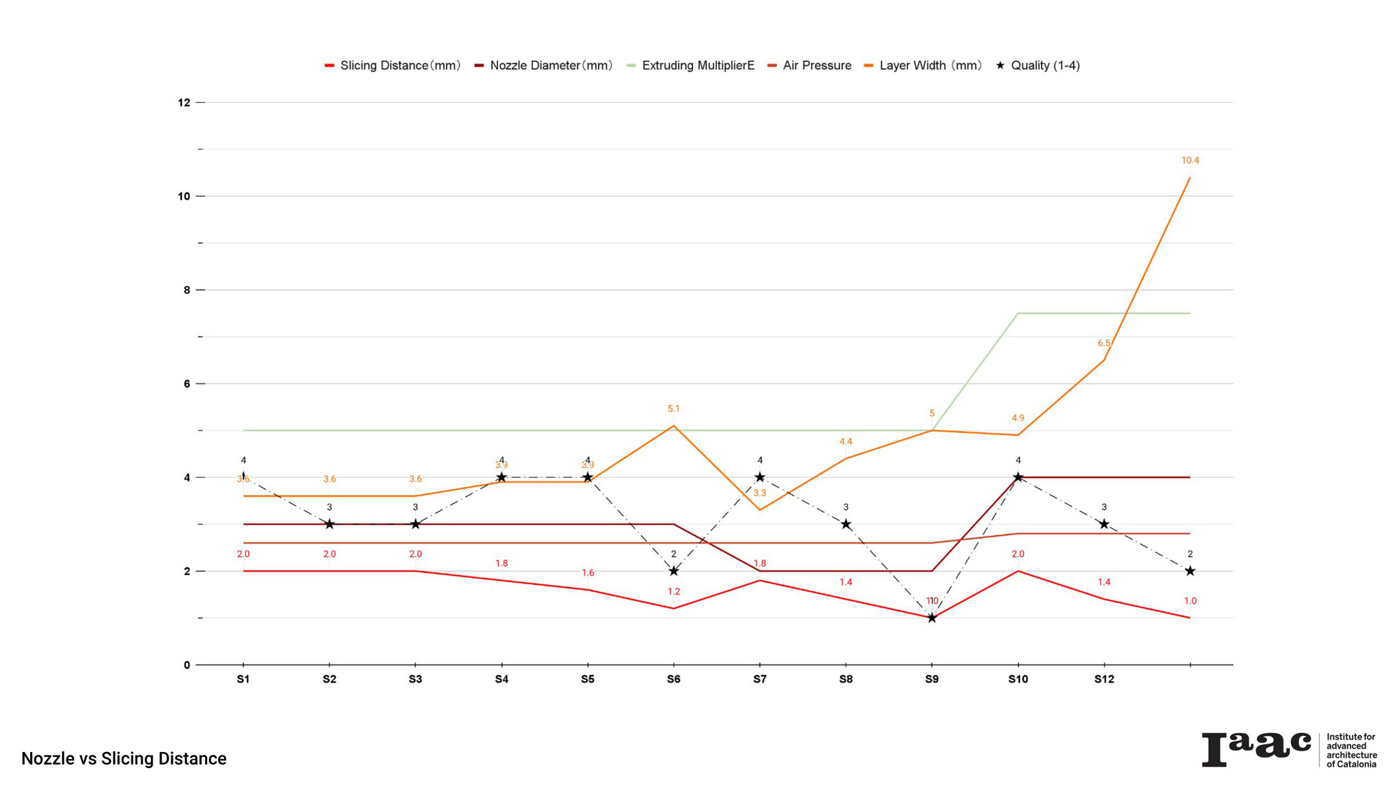
At the opposite position on the scale, as the size of the nozzle and ratio increased, the retraction step was altering the print due to the strength of the flow that was lifting part of the already extruded layer resulting in a distortion of the whole geometry.
Another key aspect that we took into consideration was the printing time, an increased diameter of the nozzle led to a reduced printing time. Therefore, in order to verify the conclusion and improve the performance of the nozzle size of 4mm to continue printing with this size in the next samples, the ratio (Sd/N) was decreased to 0.37.
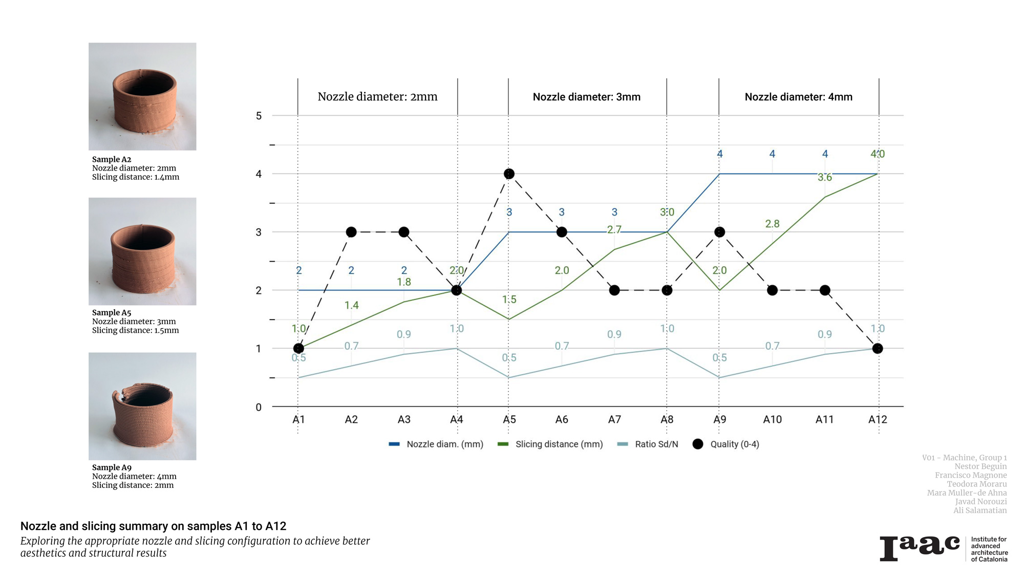
In conclusion, for a nozzle diameter 3 mm, a ratio around 0.5 is resulting in a qualitative extrusion that has both a stable structure integrity in terms of layer compacting and a feasible printing time. While for a nozzle below diam. 3 mm, the better results were obtained with a larger ratio between 0.7-0.9, at a ratio of 0.5 the reduction of air pressure and the Extruding multiplier E was required in order to avoid the over extrusion. Meanwhile, for a nozzle diam. 4, while the material used was increasing, increasing the Extruder Multiplier E value and Air pressure was an additional strategy to ensure a good printing result.
Failed tests happened due to technical difficulties which turned into lessons: to maintain the quality of overnight clay the cartridge should be sealed and revision of the parameters when printing with new clay is required.
Also, at a ratio (Sd/N) of 1 between the Slicing distance and Nozzle diameter, increasing the print speed was not a solution.
2. Feedrate
Alternating between different feedrates (F mm/s) and constant pressure (Bar) to explore the ideal linear distribution of material with different densities.
Starting from the primary geometry (Cylinder h=50mm, diam. 70mm) and using the adjusted parameters of the above conclusion (Nozzle diam. 4mm, Slicing distance 1.5mm, Ratio Sd/N 0.4), we explored the impact of the material flow speed in the extrusion. The iterations tested a feedrate of 1000 / 2000 / 3000 / 4000mm/s.
Sliced Geometry:
- Nozzle diameter: ?4mm
- Slicing distance: 1.5mm
- Ratio Sd/N: 0.4
Printing parameters:
- Feedrate (F mm/s): 1000-4000
- Jog Speed: 4000
- Extruding Speed (E): 5
- Retraction Setting: 0
- Safety Offset: 5
- Pressure (Bar): 1
3. Extruder Multiplier
Observing the impact of the extruder speed on prints with the same slicing distance, pressure and printing speed.
Sliced Geometry:
- Nozzle diameter: ?3mm
- Slicing distance: 1.8mm
- Ratio Sd/N: 0.6
Printing parameters:
- Feedrate (F mm/s): 2000
- Jog speed: 4000
- Extruding Speed (E): 4-16
- Retraction Setting: 0
- Safety Offset: 5
- Pressure (Bar): 1.6-2.5
The peak performance for this setup was found at a multiplier of around 10, higher values require much more material resulting in over extrusion and lower values resulted in toolpath malfunctions and weakly under extrusions, hence the geometry was unstable and collapsed in every case.
The amount of material being printed is depending on reducing or increasing the Extrusion Multiplier E value.
Increasing the E value, and reducing the Feedrate to values around 2000 was required to obtain a coherent extrusion, while in an elevated Feedrate and E values, the material faced machine drawbacks, the stepper motor can not coordinate with the printing speed and the extruding multiplier.
A constant increase between the multiplier and the thickness of the extruded layers was observed, at a ratio of almost 1:1, while keeping the rest of the parameters constant.
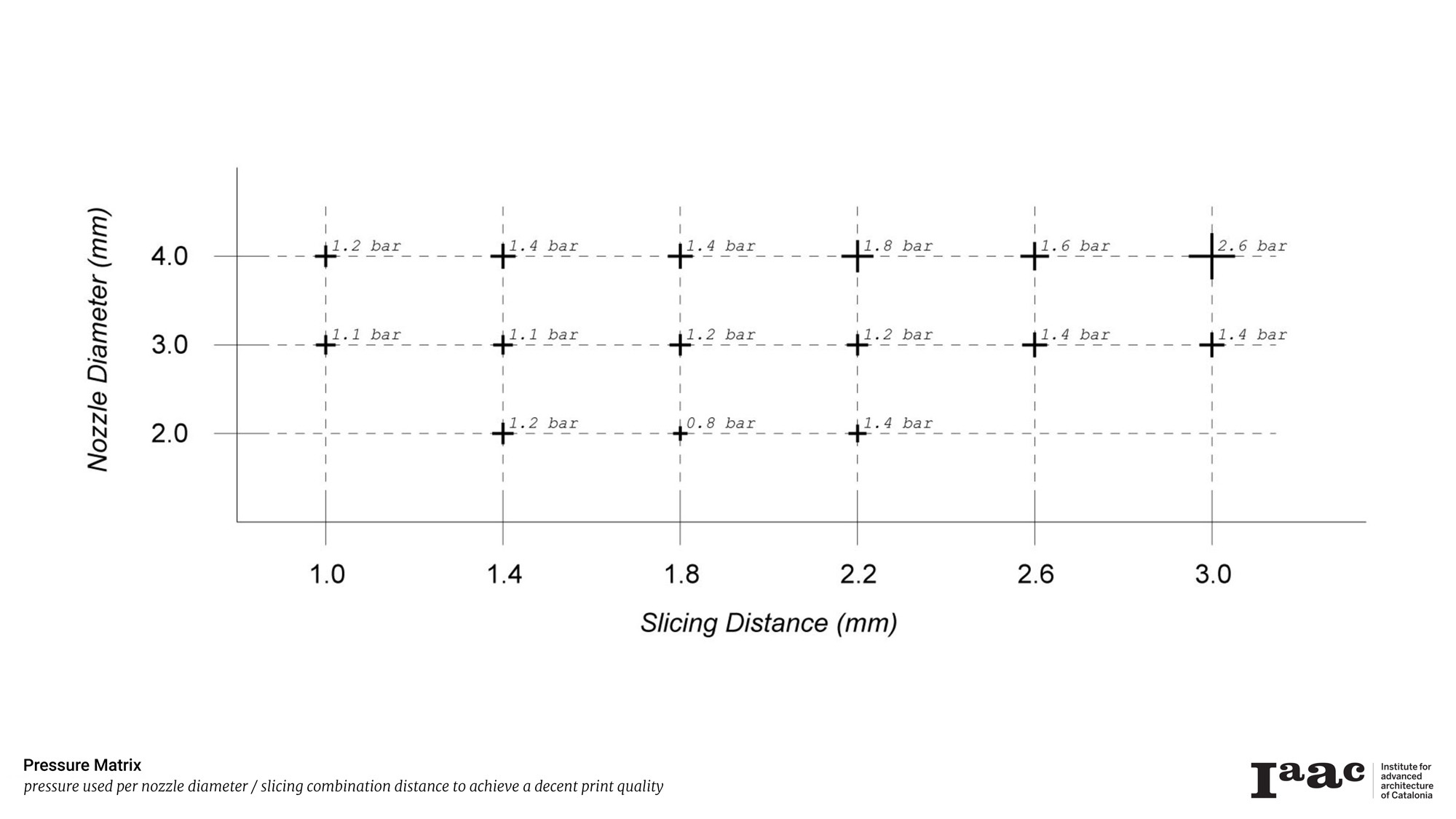
Print speed is directly proportional to print quality. While taking into consideration the above-mentioned parameters, the additional step was adjusting the pressure while noticing a quality decrease related to increasing the slicing distance and nozzle diameter. While in the cases of a thinner slicing distance and a ratio below 0.5 the pressure required was almost constant, in the cases of increasing the slicing distance, more pressure was needed to achieve the desired print quality.
4. Seams and toolpath
The next exploration was dedicated to the impact of machine movement in the extrusion process. Under previous tests, we concluded that the stepping back of the nozzle impacted the whole additive manufacturing process and led to alterations in the printed geometry. Thereby, we studied different linear movements of the machine in order to identify the ideal results of the parametric and machining calibration for the clay extrusion.
_____________________
Iterations with different seams and toolpaths
Generally using a continuous toolpath resulted in better outcomes than seam.
Some common errors/malfunctions while printing – Toolpath error leading to excessive material deposition at a point resulting in stagnated geometry, lower pressure loading to open seams, 25% increase in the extrudable pressure resulting in closing the seam. Troubleshooting required resetting the printer and the Repetier host in case of abrupt stopping of the printer.
Seam
A. Custom Seam
Having different steam locations makes it hard to track the G-code for us. Generally, this seam pattern would be helpful to fade the seams in a custom print pattern.
B. Random Seam
Random seam provides a much more homogenous distribution in our geometry which probably results in better bonding between layers and avoids generating a weak connection. Although the appearance results are not desirable if it is not solved in final print patterns and the material plasticity is not propitious.
C. Spiral Seam
Spiral seam had the best results in terms of both aesthetics and reducing stops and unexpected movements.
Toolpath
D. Step-up
Using a Step-up toolpath we reduced the unexpected movements during printing and we obtained a smoother texture and resolution avoiding residue creation due to the nozzle retraction.
E. Spiral
The ideal result was obtained using this continuous Spiral toolpath, the whole path is aesthetic and flawless throughout the whole print. Also, unexpected movements were not happening in this case.
F. Alternate
The Alternate toolpath looks like a regular seam but it gives a smoother and much more coherent printing texture. Having a single curve in the whole printing path ended up reducing unexpected movements as other toolpaths as well.
Further explorations
After identifying the most optimized parameters for coherent extrusions, further toolpath explorations implied customization of the scripts to develop a spiralized contour of any shape and introduce undulations in the horizontal plane, or a spiralised contour in the vertical plane with varying layer heights, from 1 to 1.8 mm. In the previously mentioned test the print speed was adapted in the range of 800 to 1200 mm/s while printing, in order to deposit less material on the thinner layers.
One final exploration was regarding the overhanging capacity of the layers, and again, custom scripts were developed.
_____________________
Conclusions
Maintaining a ratio (Sd/N) between the slicing distance (Sd) and nozzle diameter (N) under or equal to 0.5, increasing the feedrate to 4000 mm/s and setting the printing in continuous spiral toolpath results in a coherent print with a good aesthetic and good potential static behavior due to the impeccable connections between its layers.
Strategies were needed to overcome a myriad of printing challenges and inconsistencies in extrusion. Most of the inconsistencies were related to the material or printer hardware, including air in the mix, material excessively dry, slow motor speeds, connection issues between the printer and the software, or pump exhaust.