
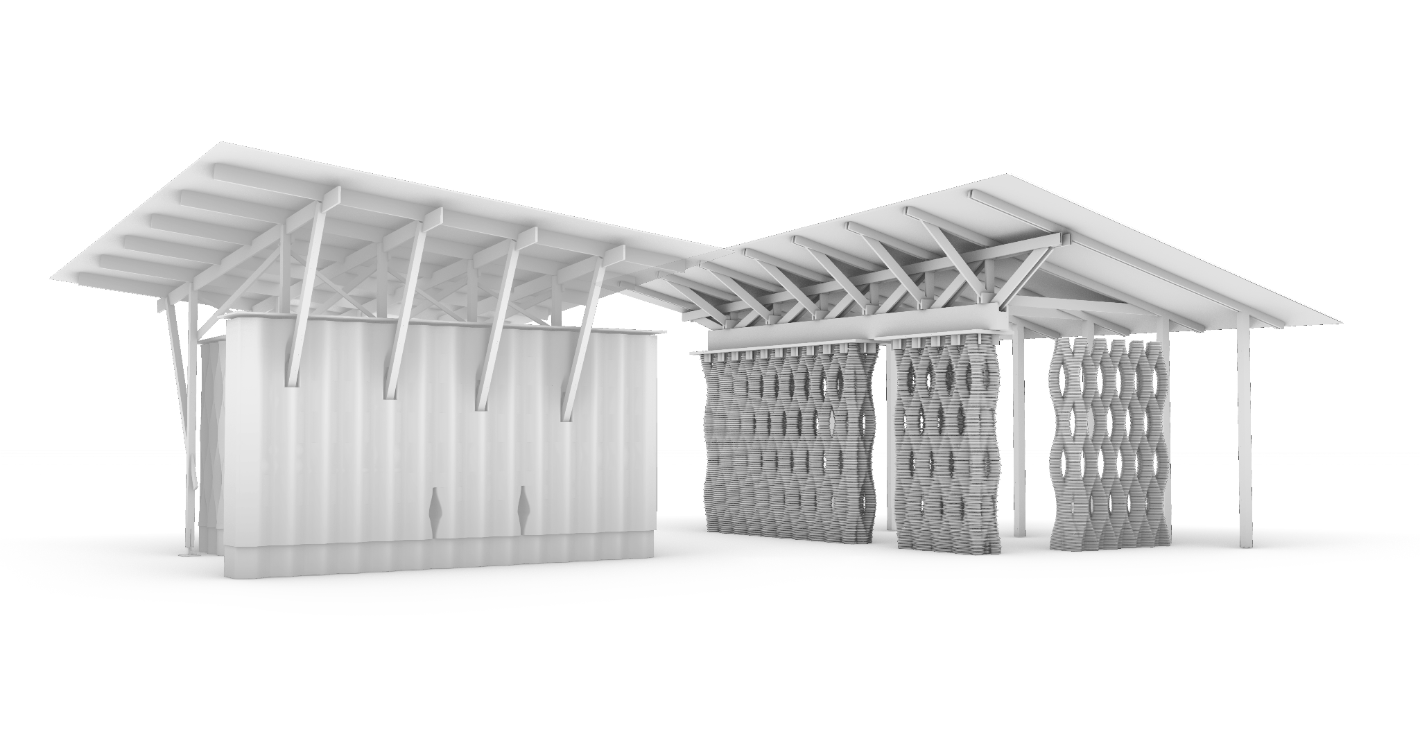
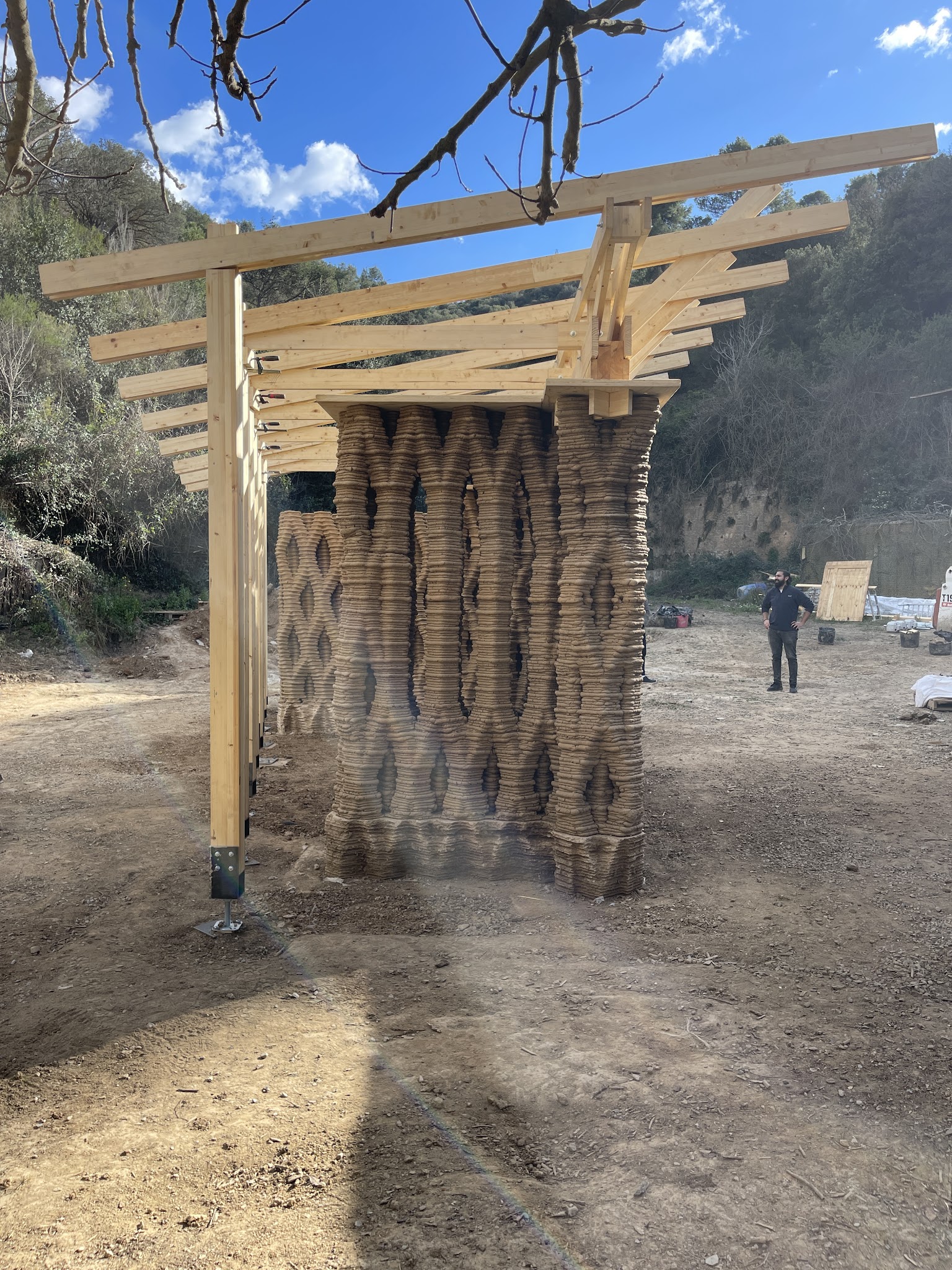
Perspective of Teixit – Source: Vesela Tabakova
Design to Production
A. Wall Axis and Segmentation
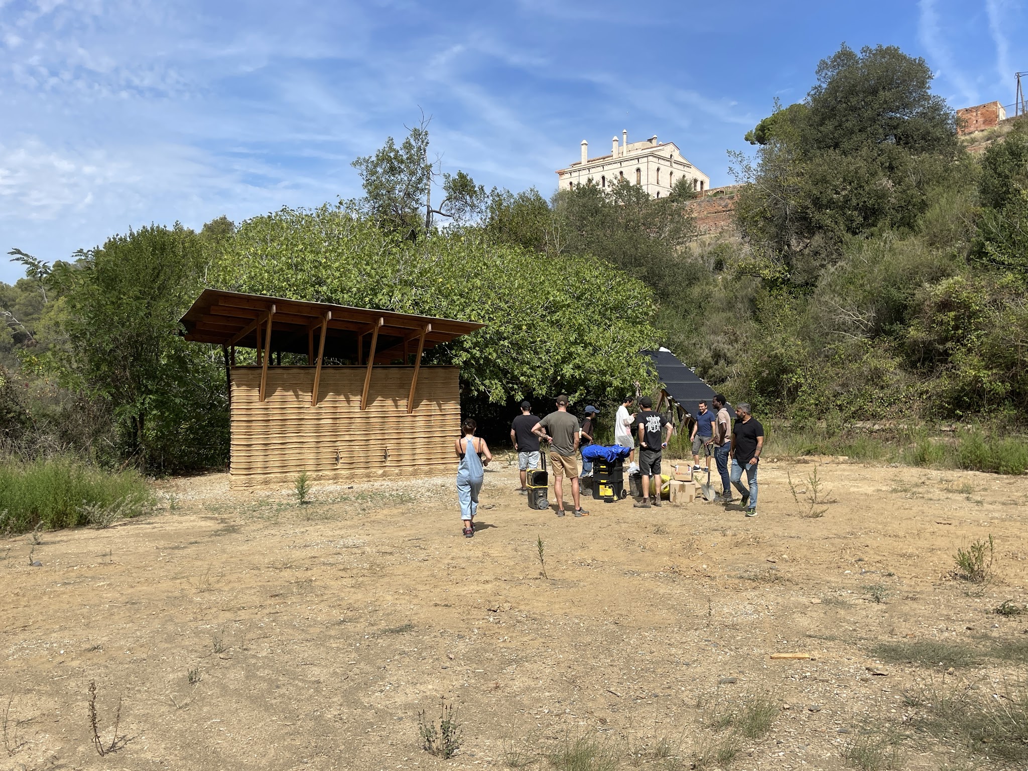
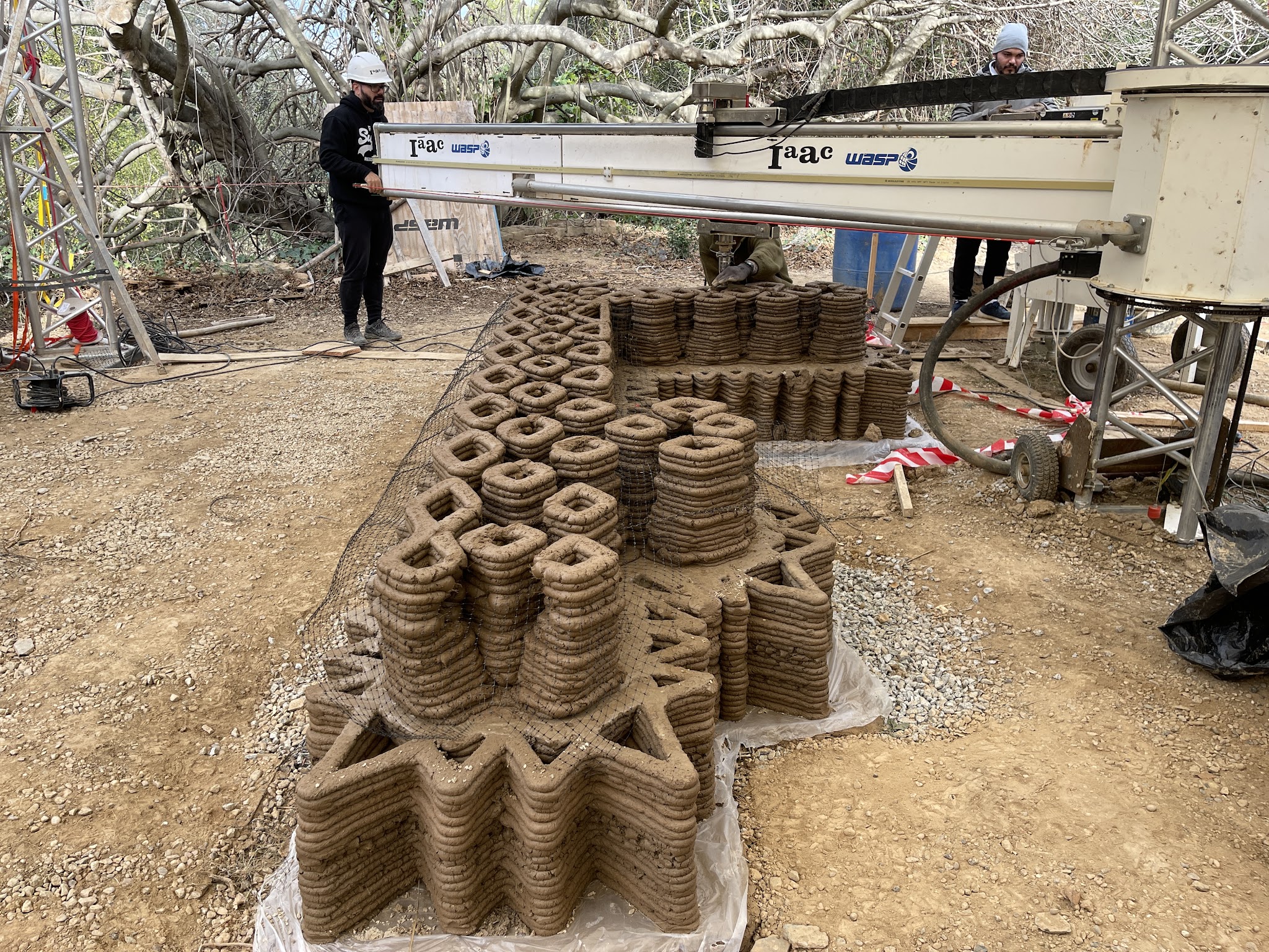
Situated in Valldaura Labs, Caserolla Park, Barcelona, Teixit is a conceptual step towards a 3D printed living complex for the Mediterranean climate. It expands the existing TOVA bedroom pavilion by incorporating a kitchen and a living room. This space, serving as an open-air fabrication lab until the completion of the complex, is dedicated to future student generations. The open-air pavilion and the resulting outdoor spaces create a holistic ensemble with the existing context furthering the purpose of study, experimentation, and fabrication at Valldaura Labs.
The in-situ walls were strategically placed to complement the surroundings, framing work areas and outdoor spaces. Positioned between existing and new structures, a tranquil patio, a peaceful space in front of a prominent tree, and an expansive open space enhance the complex. Wall alignment and segmentation were guided by practical considerations, including the WASP Crane printer’s reach and maneuverability, cost-effective use of existing foundations, and structural and time constraints, influencing segment length and buttress addition.
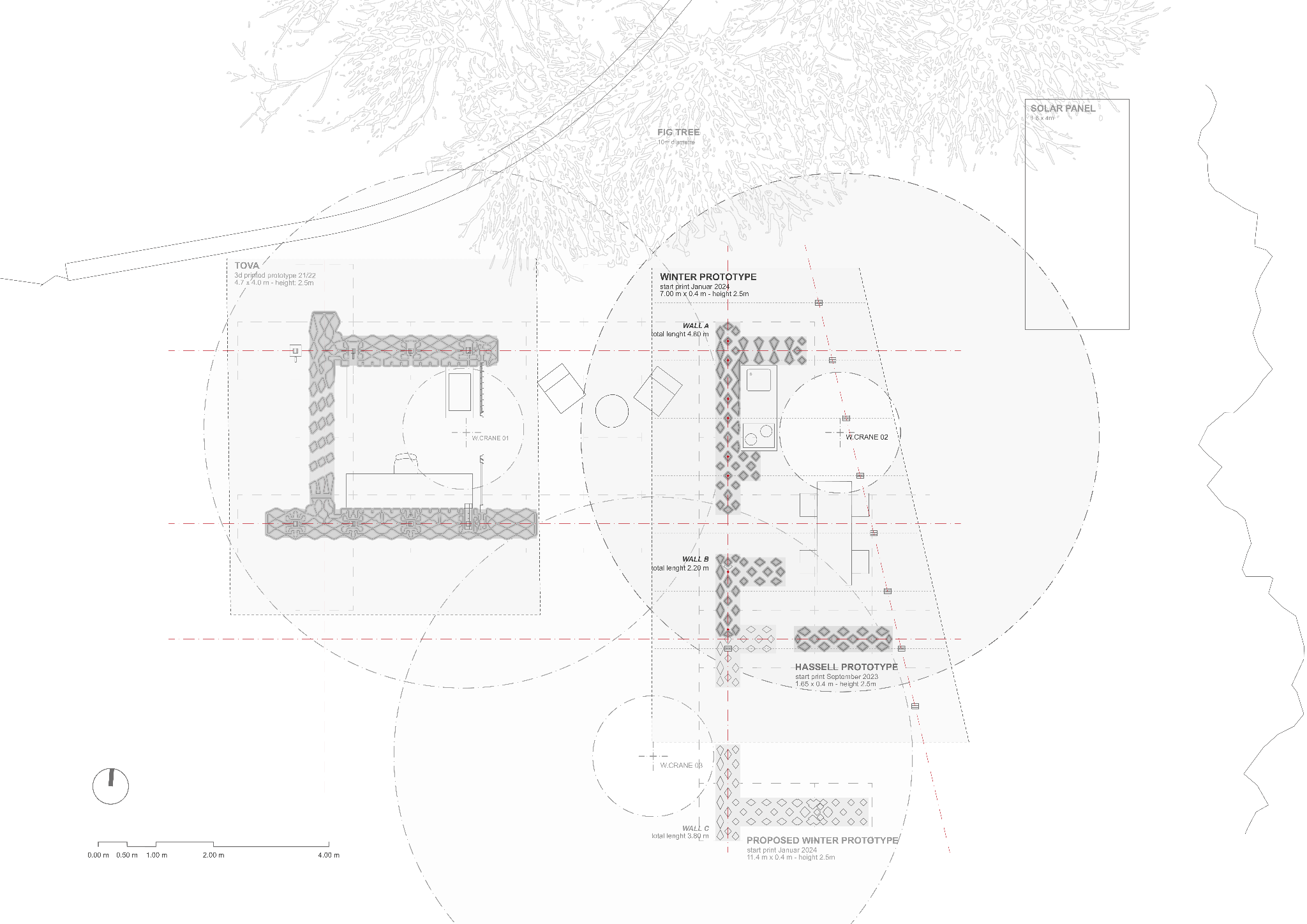
Teixit, Masterplan – source: Vesela Tabakova
B. Pattern modification
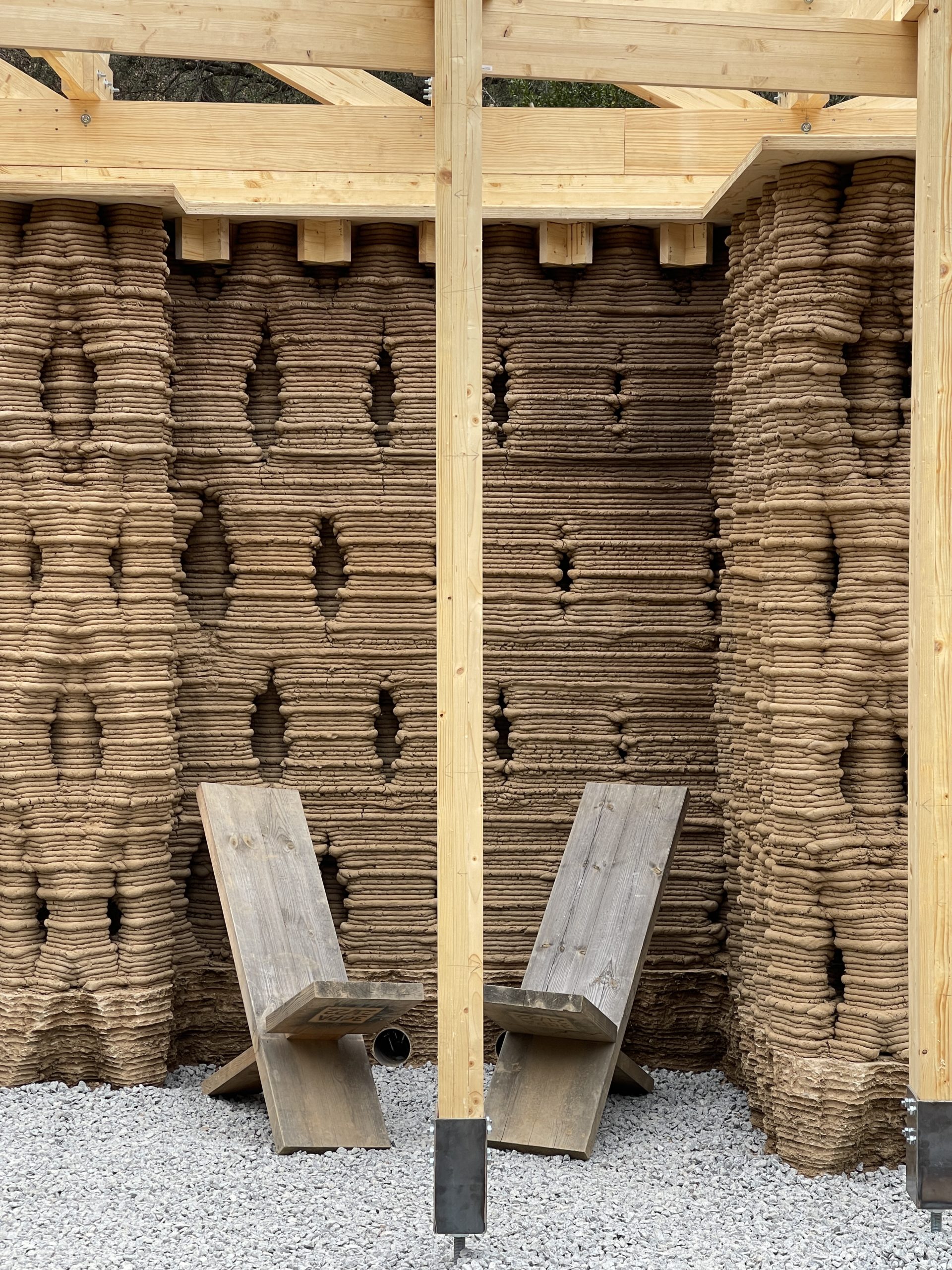
The diagrid space frame developed during Techne and Research, was modified to match the spatial and structural functions arising from the orientation and anchoring. The different strata of the wall were treated differently according to the functions they were subjected to. Starting with outermost strata, the pattern profiles were modified with a gradient that allowed the transition from completely closed to a perforated surface, that also translated to a transition from a private to a more public space.
Further, the middle strata of the wall was assigned a purely structural function housing the roof anchoring profiles. The pattern profiles, where the diagonal cables would be driven through, were stretched along the wall axis to create tolerance for discrepancies caused by the shrinkage of the walls or movement of the roof structure. The profiles of the inner-facing strata of the wall, where a kitchen space was planned, were flattened to allow for the easy installation of furniture. Finally, vertical segments were introduced on the buttress facing the fig tree to allow for direct peaceful view towards the existing vegetation on site.
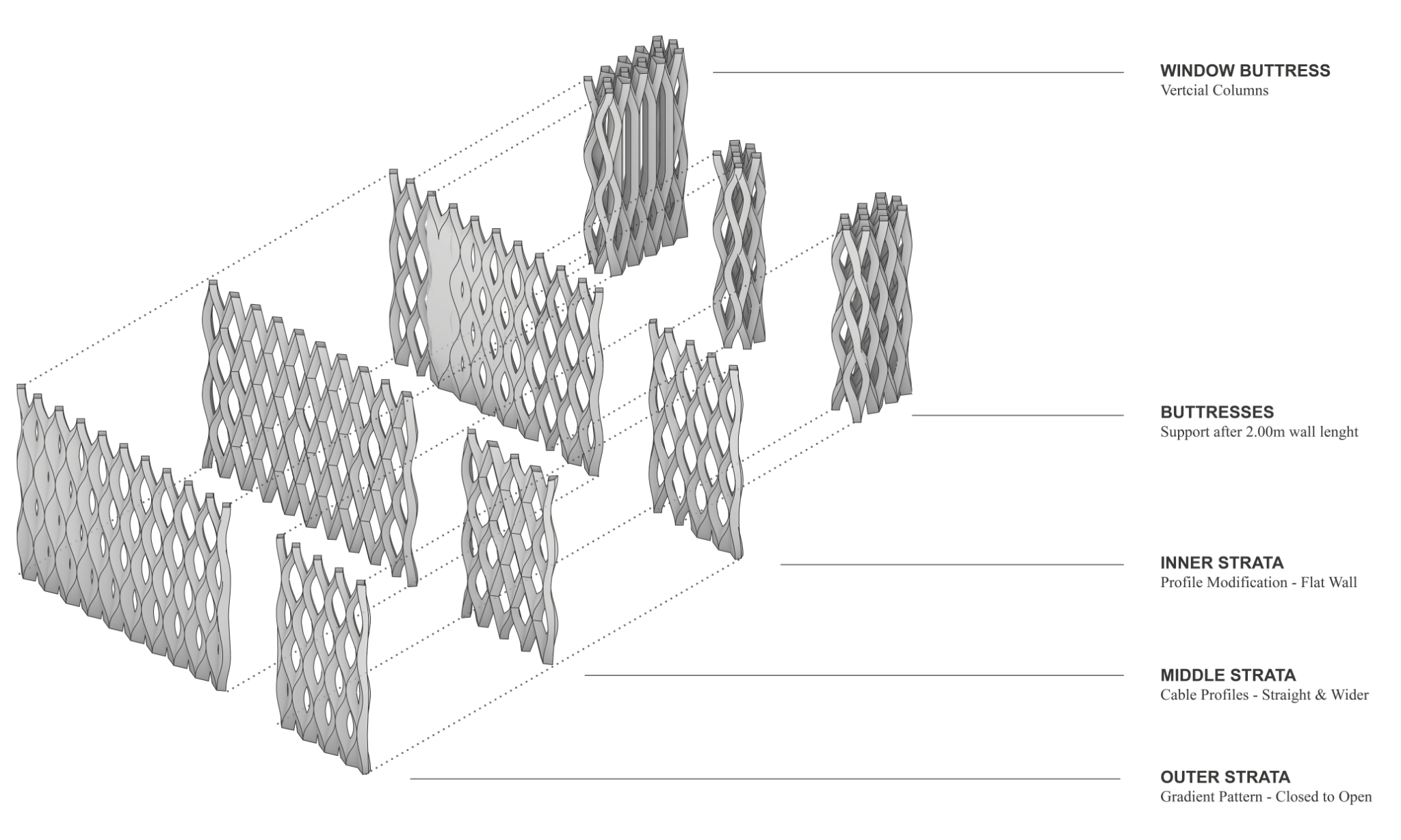
Axonometry of the different stratas of the wall- source: Vesela Tabakova
C. Foundation and plinth
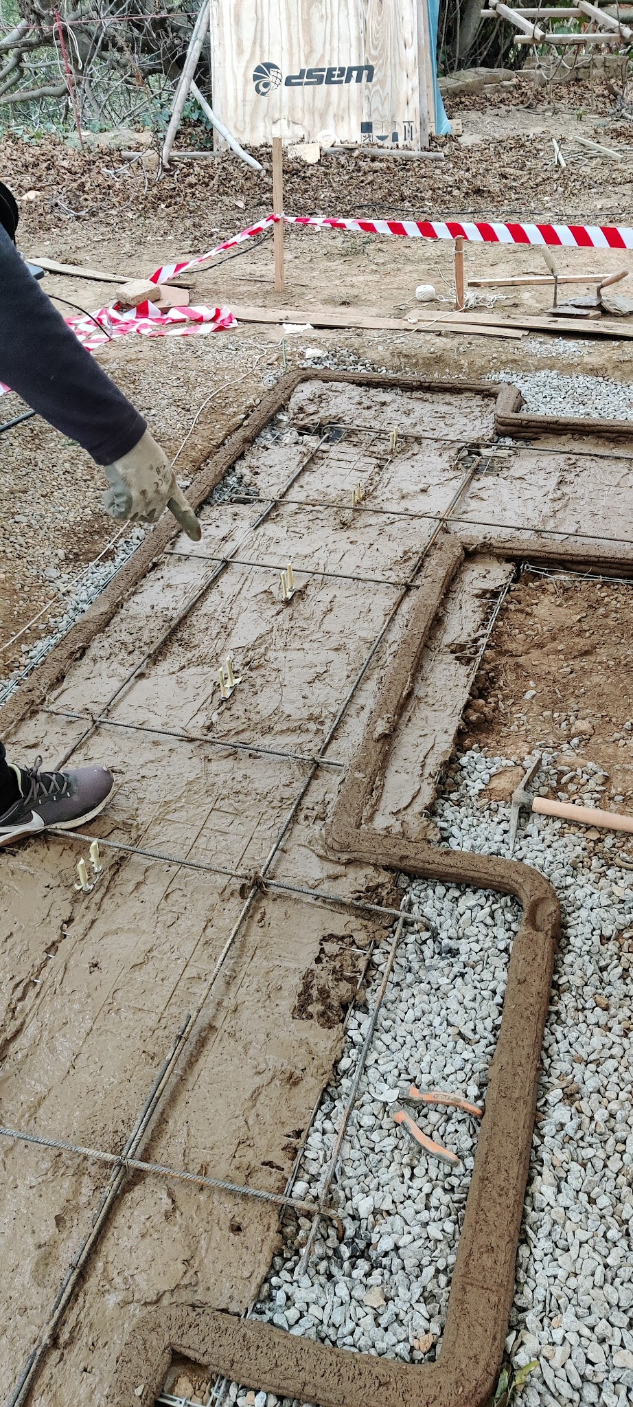
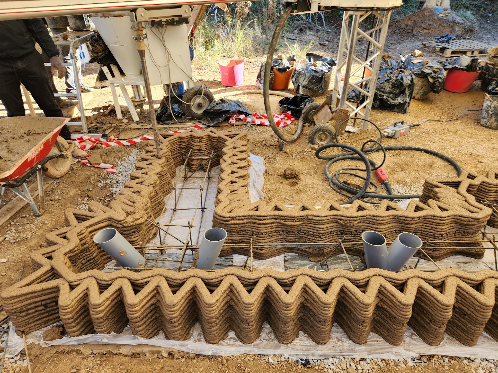
Reusable rock gabions were used as foundations for the two walls. A “plinth” or footing of poured geopolymer was constructed on top of the gabions to create a waterproof structure in contact with the ground. The plinth was constructed by 3D printing a formwork from the same earth that the walls are printed with, where the geopolymer would be cast. Before casting, a rebar lattice of 20cm by 20cm cubic cells was installed together with the PVC tube assemblies used to create cavities for the installation of the tension cables.
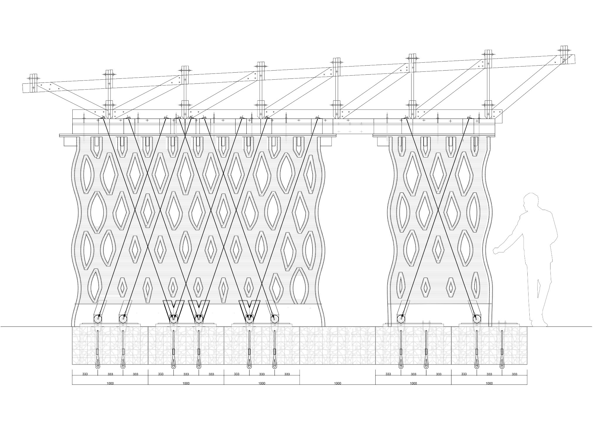
Longitudinal Section, Cable placement – source: Mark Francis, Sakshi Pawar
D. Cable connection to foundation
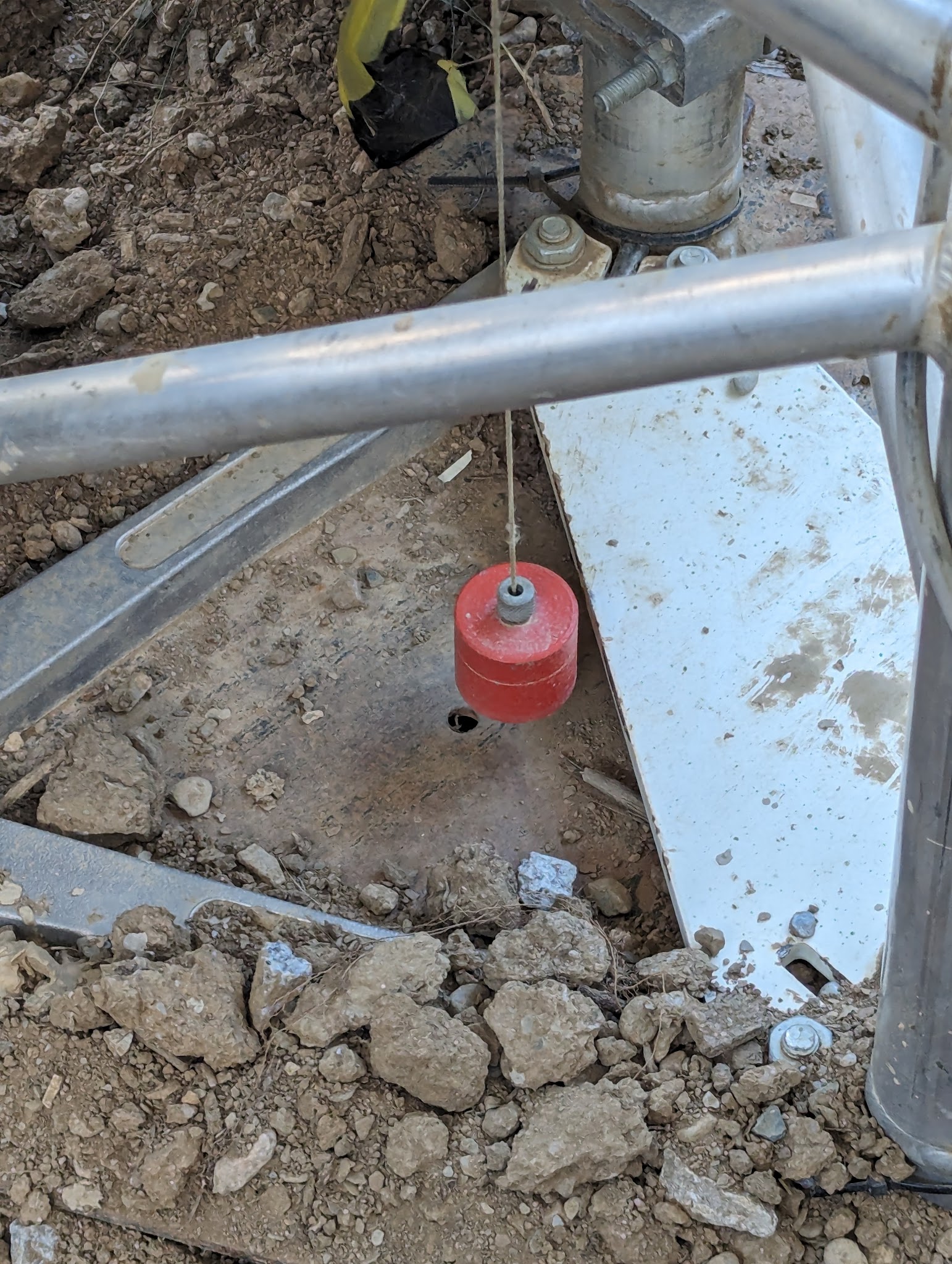
The foundational gabion system across our site consists of 1m x 1m x 50cm units, each equipped with two embedded 16mm steel cables. To address the misalignment between the gabion cables and the intended attachment points for the tensioning wall cables, a metal distribution plate was installed on top of the gabions, attached to the cables with heavy-duty u-bolts. The distribution plates were then drilled in the exact location of the cable connections and eye-bolts were secured, protected by the aforementioned PVC tube assemblies, with horizontal access holes at the bottom of the plinths. These assemblies are designed to counteract the wind lift on the roof with up to 500kg per cable.
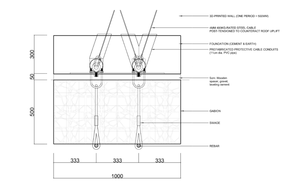
Detail Cable Connection to Gabions – source: Mark Francis
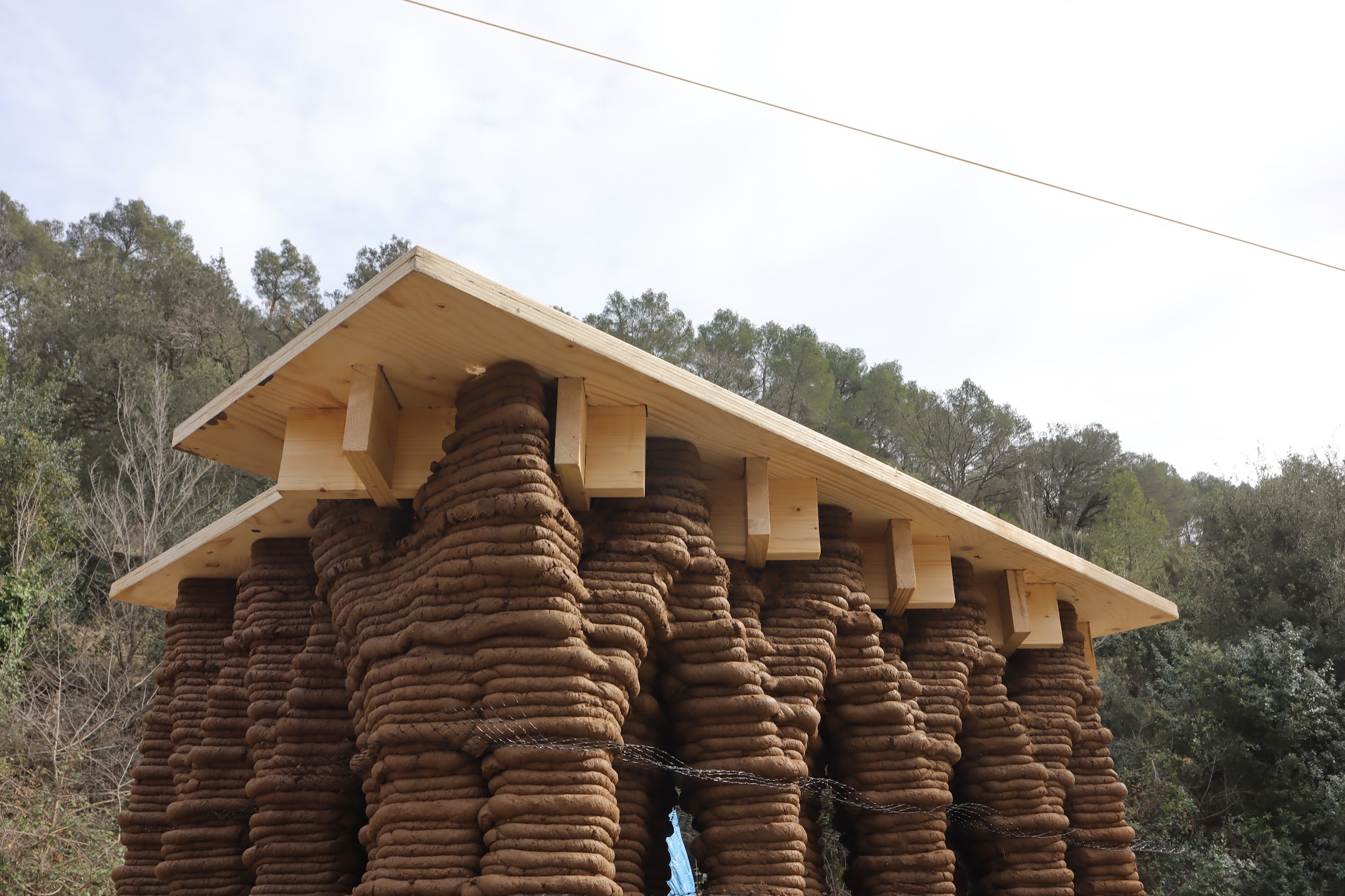
E. Wall cap & cable connection top
The connection between the wall and the truss carrying the roof is realised through multiple interconnected elements. The transition from 3D printed earth to wooden framework executed through a diagonal grid that sits between the diamond profiles of the wall. The grid is secured via a distribution plate which allows for the positioning of the T-beam spanning the two walls. The cables are secured on top of this beam and the main truss is mounted on top it. The separation of the T-beam from the maint truss allows for the equalisation of height differences between the two walls.
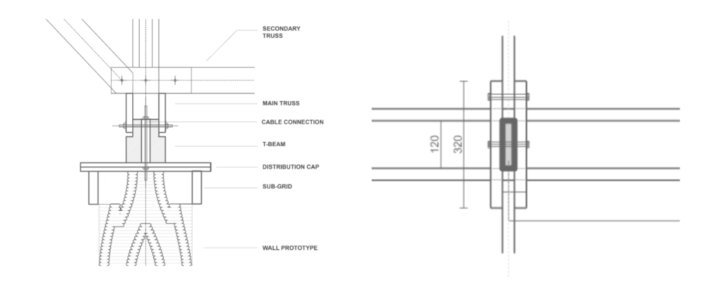
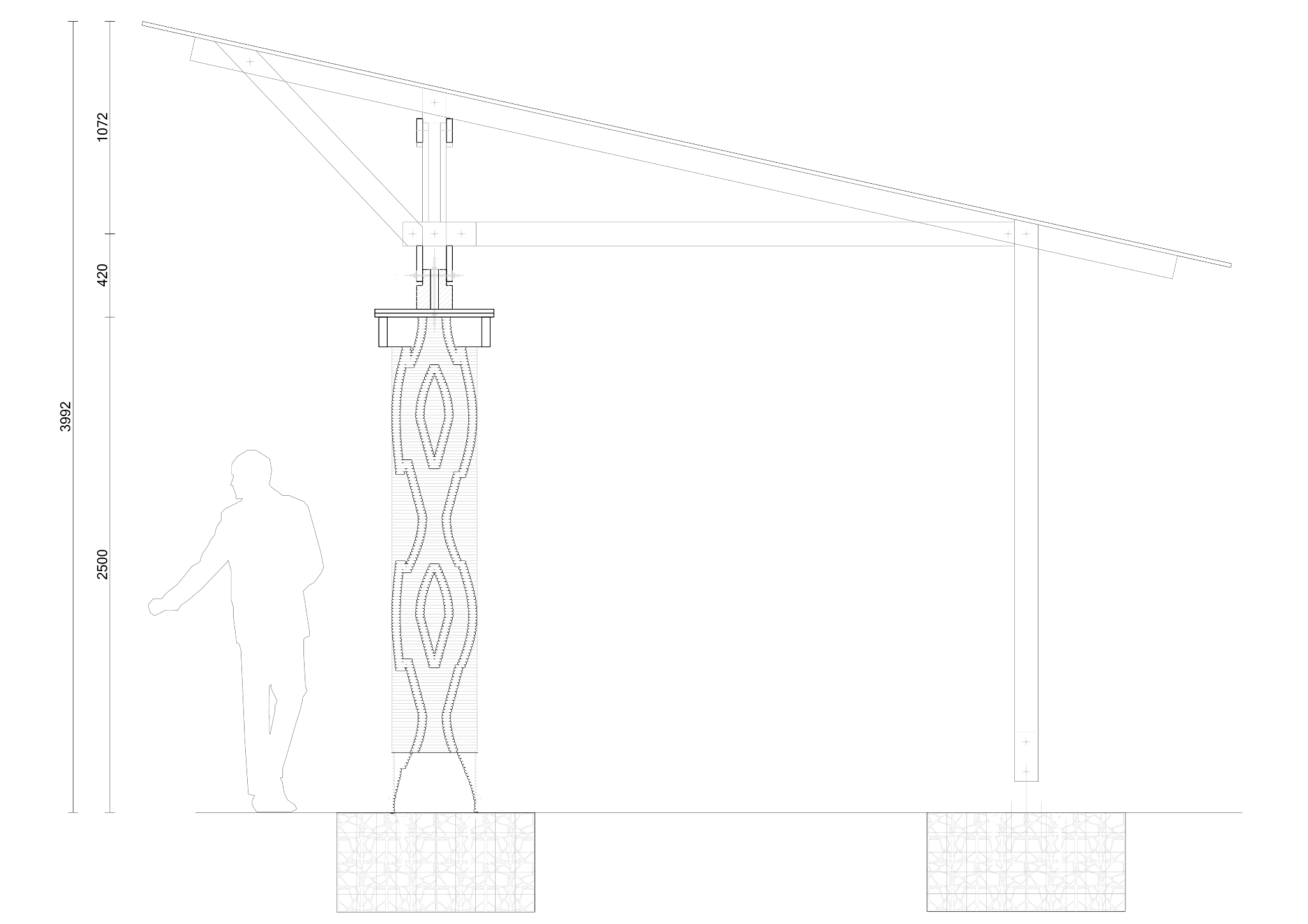
Cross Section & Detail of the Wall CapSource: Marietta Kaltsa, Sakshi Pawar
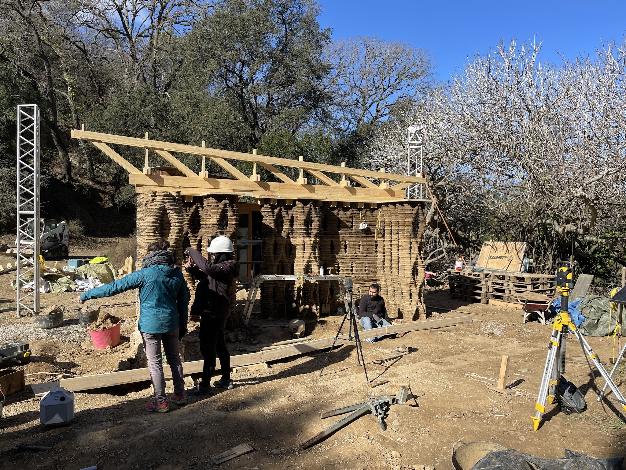
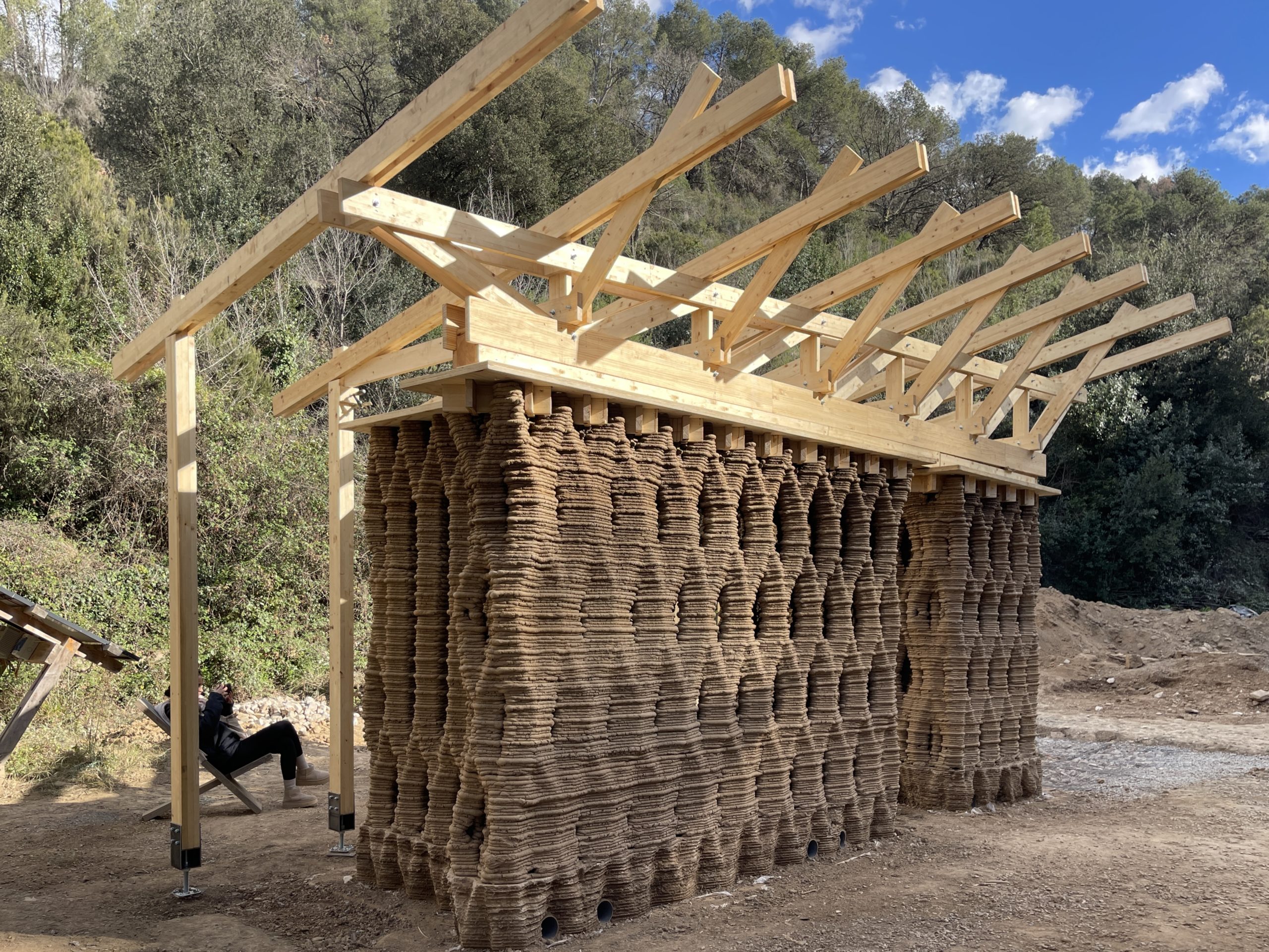
F. Roof Truss
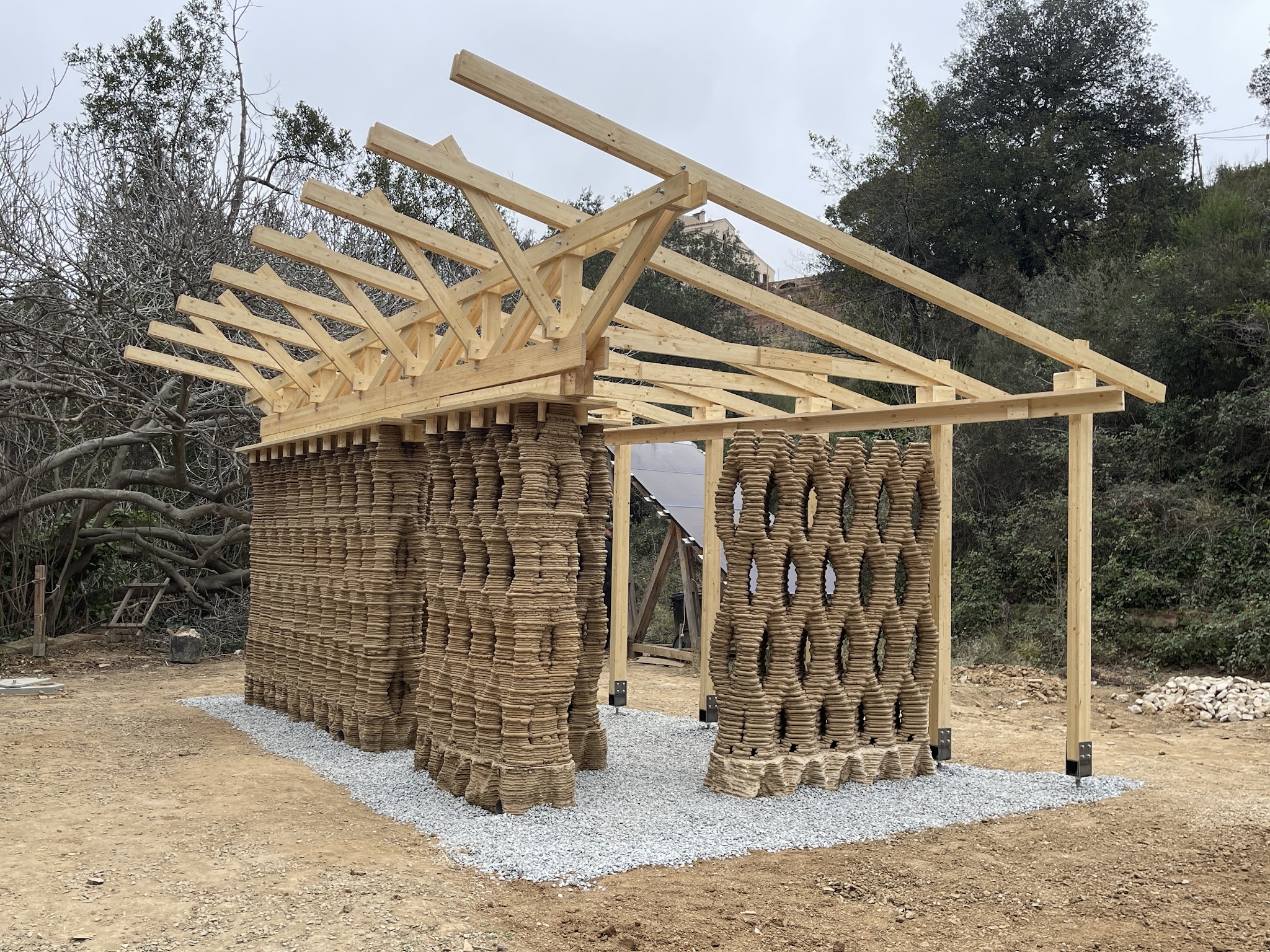
In earthen architecture is of great importance ,ensuring protection against rain and in our topic specific design, the Mediterranean summer direct sun . Therefore, the project’s double-sloped roof consists of a main and a secondary truss. The main truss was designed considering the wall’s structural grid.The elements consisting the main truss adapted to allow manual access to cable tensioning devices until the wall dries. It also supports the secondary truss and roof surfaces, distributing their loads evenly. The secondary truss extends forming cantilevers on both sides to cover the wall adequately. Regarding space design, the main axis forms an acute angle to blend with the surrounding nature, prevent excessive space expansion, and define the living area. This angle also dictates column placement .
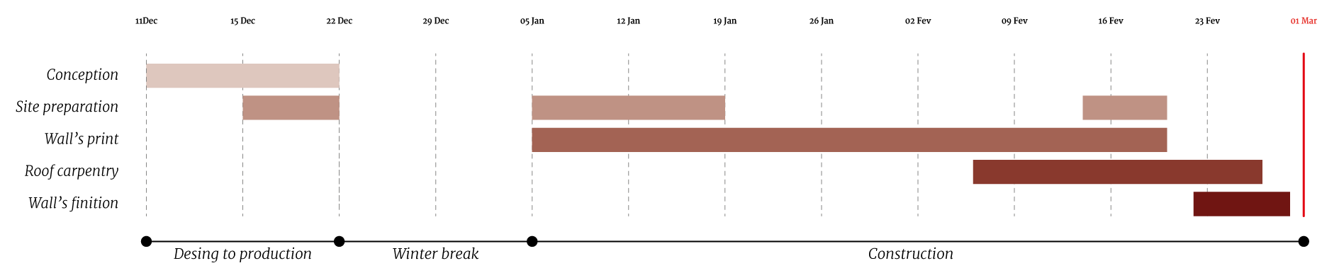
Construction Planning
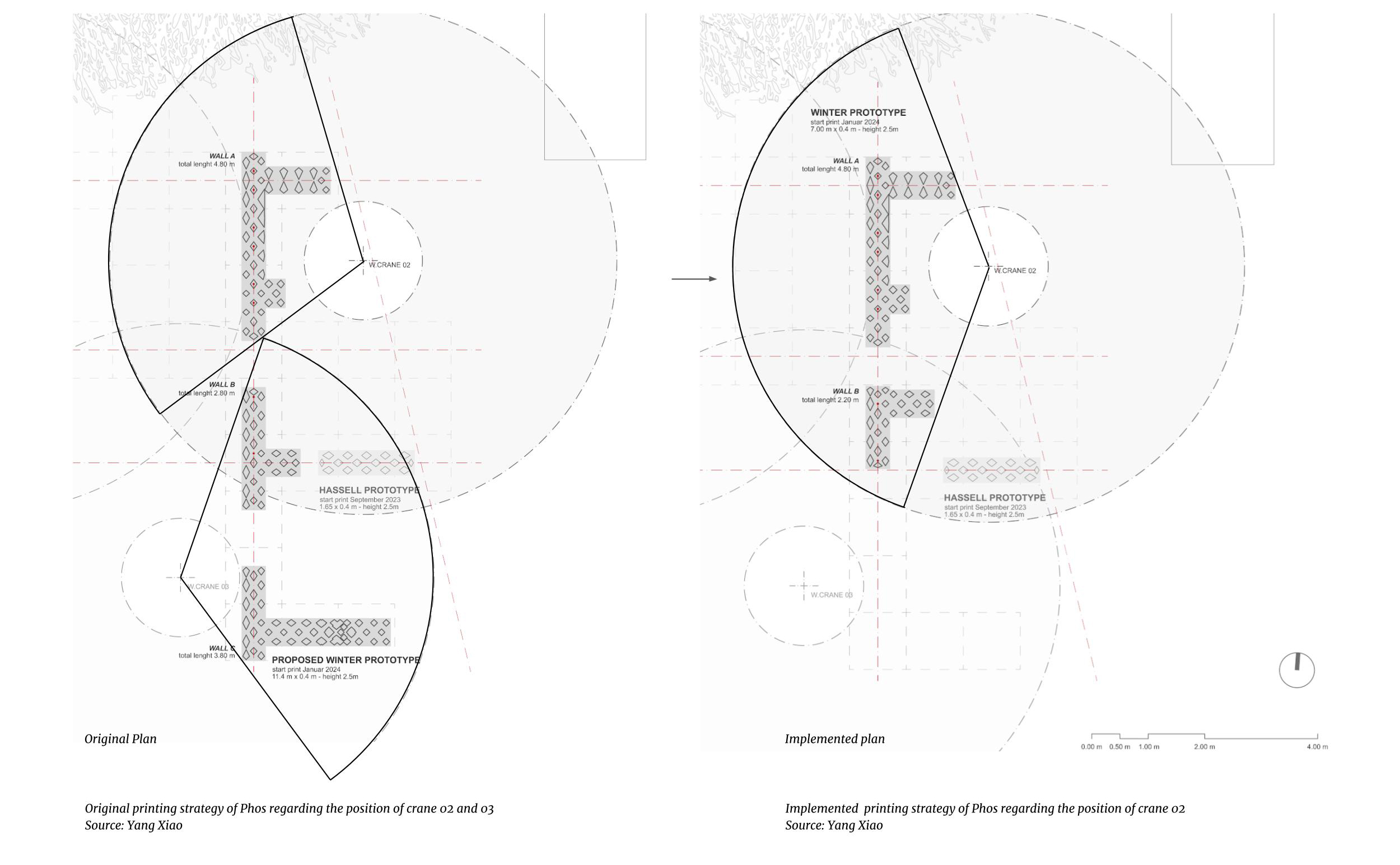
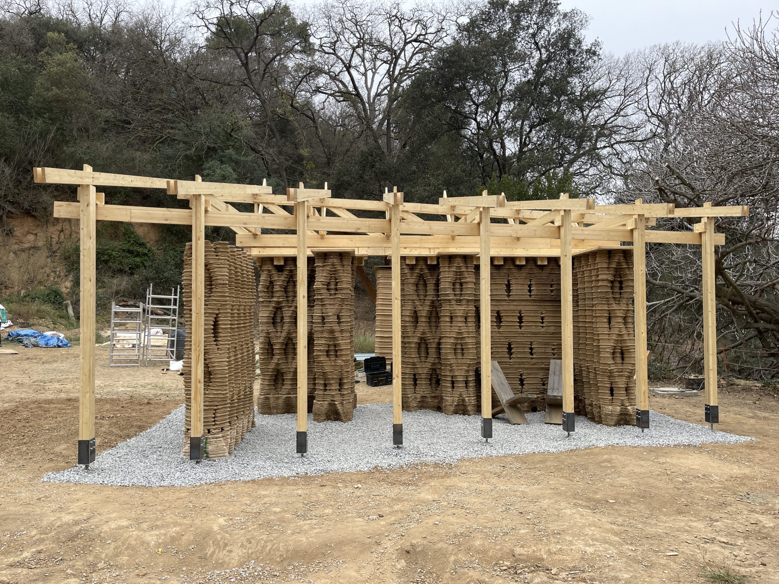
After a partial collapse of wall A nearing the end of Phase I, Phase II had to be altered. By excluding Wall C from the construction plan and remodeling wall B so that it fits the printing radius provided by the printer’s position used in Phase I, concurrent re-printing of Wall A and printing Wall B was enabled, without moving the WASP crane.
The general organization of the construction can be divided into two phases that are mainly oriented around 3D printing, but are accompanied by other important construction processes. Phase I consisted of the set-up of the construction site, the installation of the printer, placing the foundations and the printing of wall A. Phase II included a change of position so the WASP crane could simultaneously print walls B And C and the fabrication and installation of the roof.
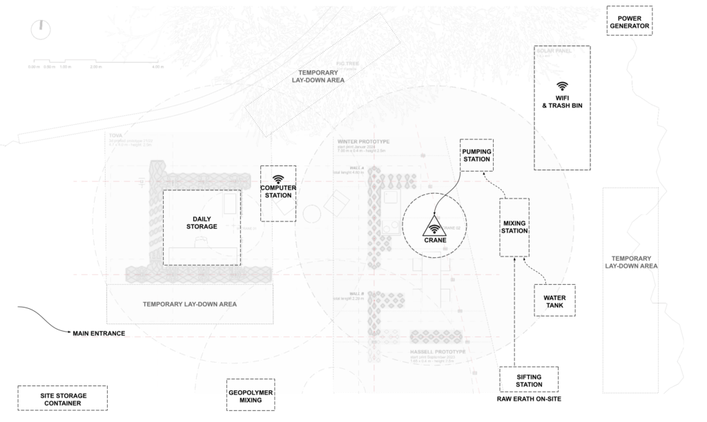
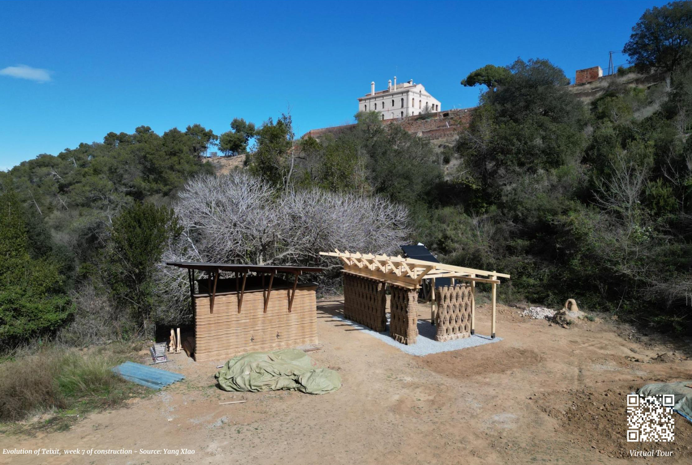
Plan of the site Organization – source: Yang Xiao
1:1 Scale
A. Site organisation
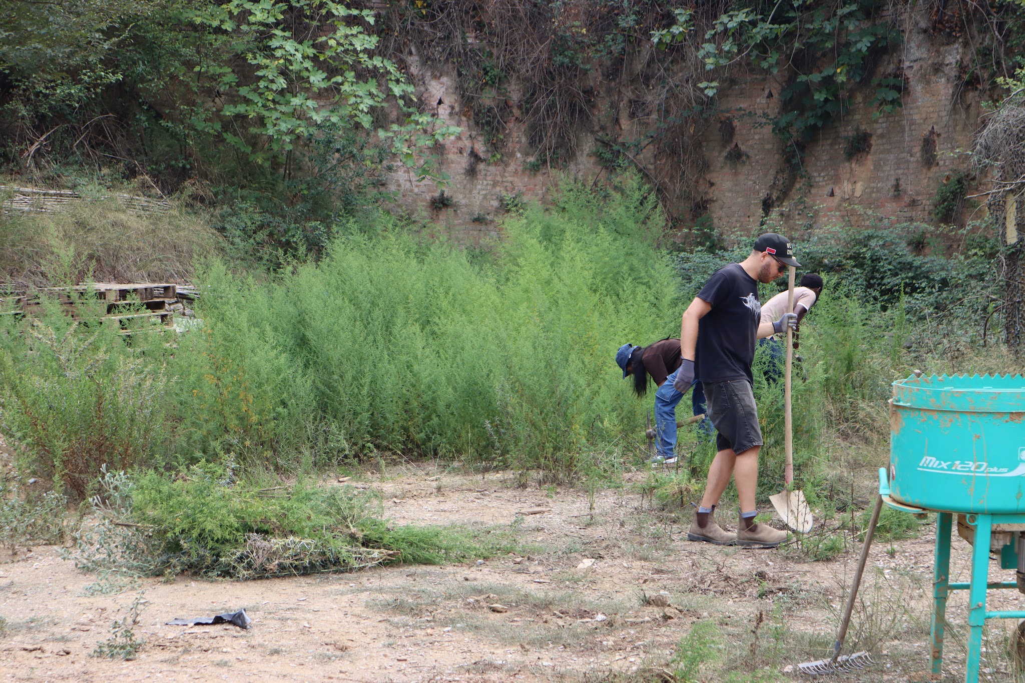
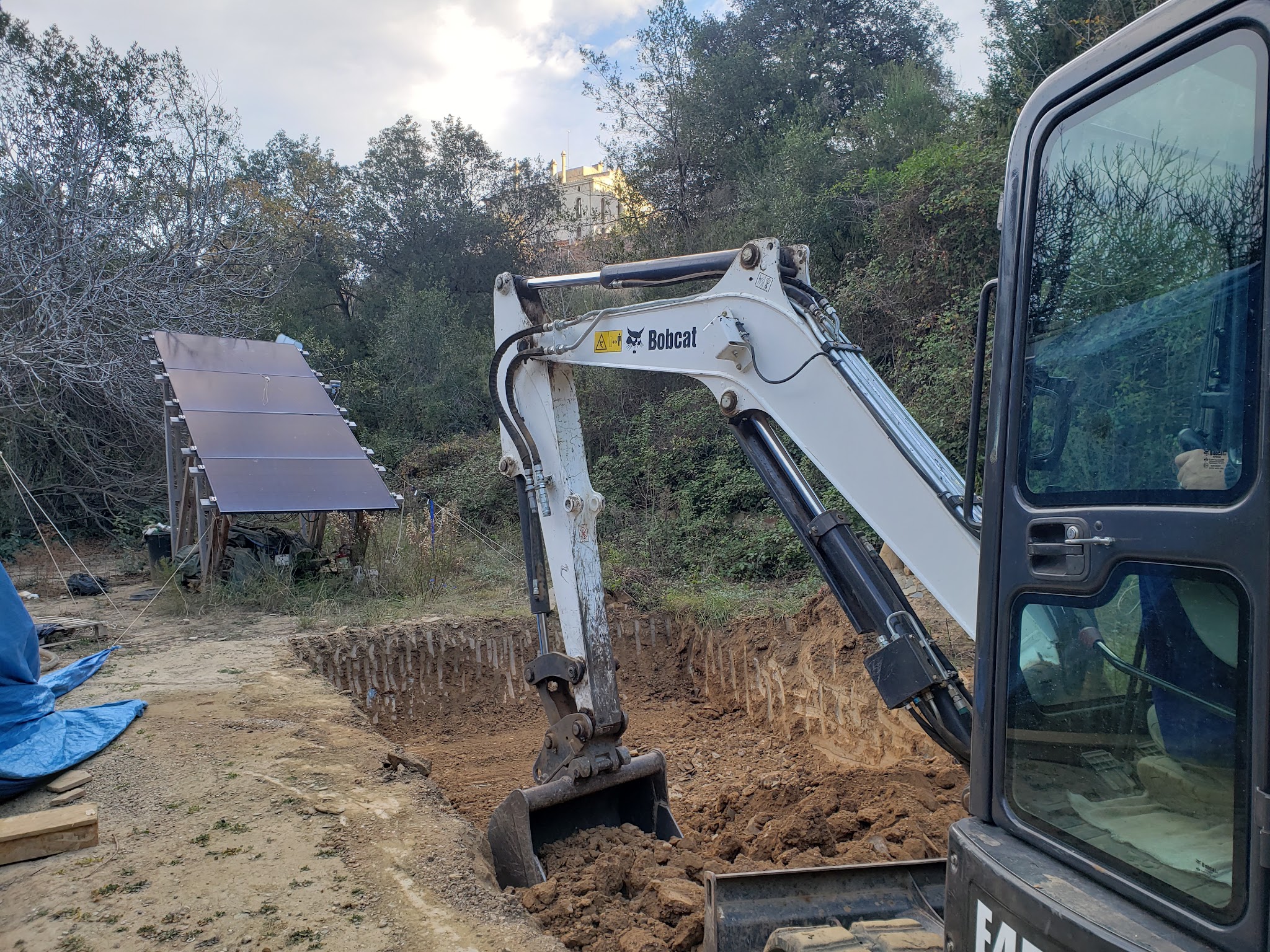
Site Preparation: Due to the site being situated in a natural environment with overgrown vegetation, including weeds, and tree branches within the planned printing area, it is necessary to commence with site preparation. This involves clearing the area of weeds, stones, and other debris, leveling the ground, planning the construction pathways, and positioning construction equipment and materials within the designated area.
Crane Preparation : Transporting crane assembly components to the construction site.
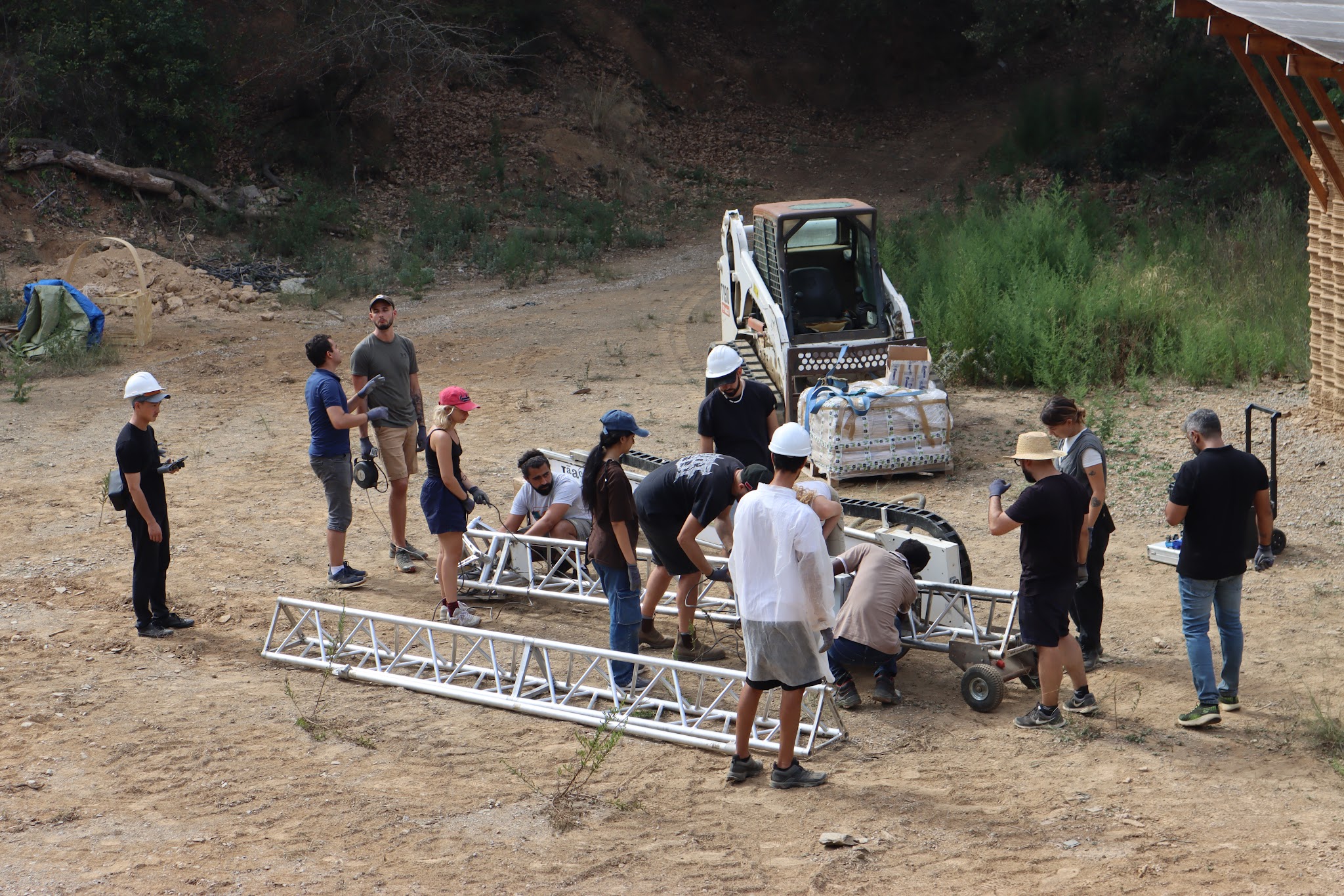
Crane assembly : Assemble the crane and place it on a pre-set concrete foundation. Install two additional gantry columns for future tarp placement.
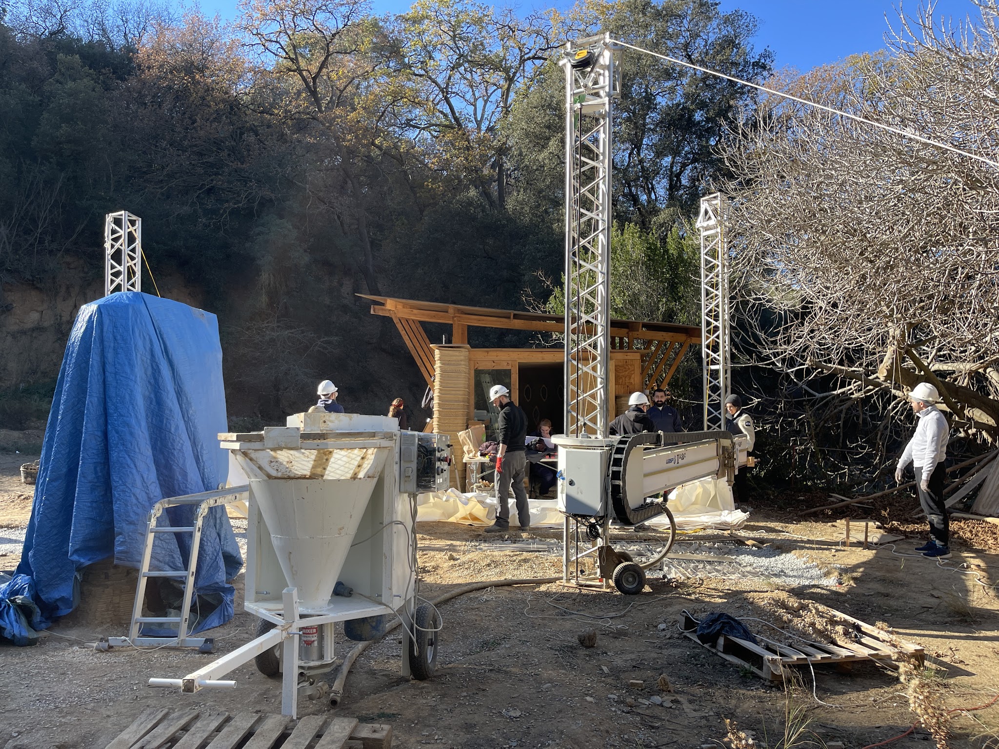
Tarp Setup: Setting up a tarp to provide shade to the print site. Keep the earth in shade can control the dry speed and avoid crack.
Crane Calibration: By adjusting the lengths of three directional fixings located at the top of the crane columns, ensure that the crane maintains a vertical orientation. Continuous checks are required to account for factors such as wind forces, the crane’s own weight, and other site conditions, ensuring the center of gravity remains in a central position.
Computer Station: The computer station is operated by one person. The operator is responsible for controlling the crane, like moving the crane arm and nozzle, loading 3D printing files and so on. During the printing process, real-time control of the crane’s operating speed and the extrusion speed of the nozzle.
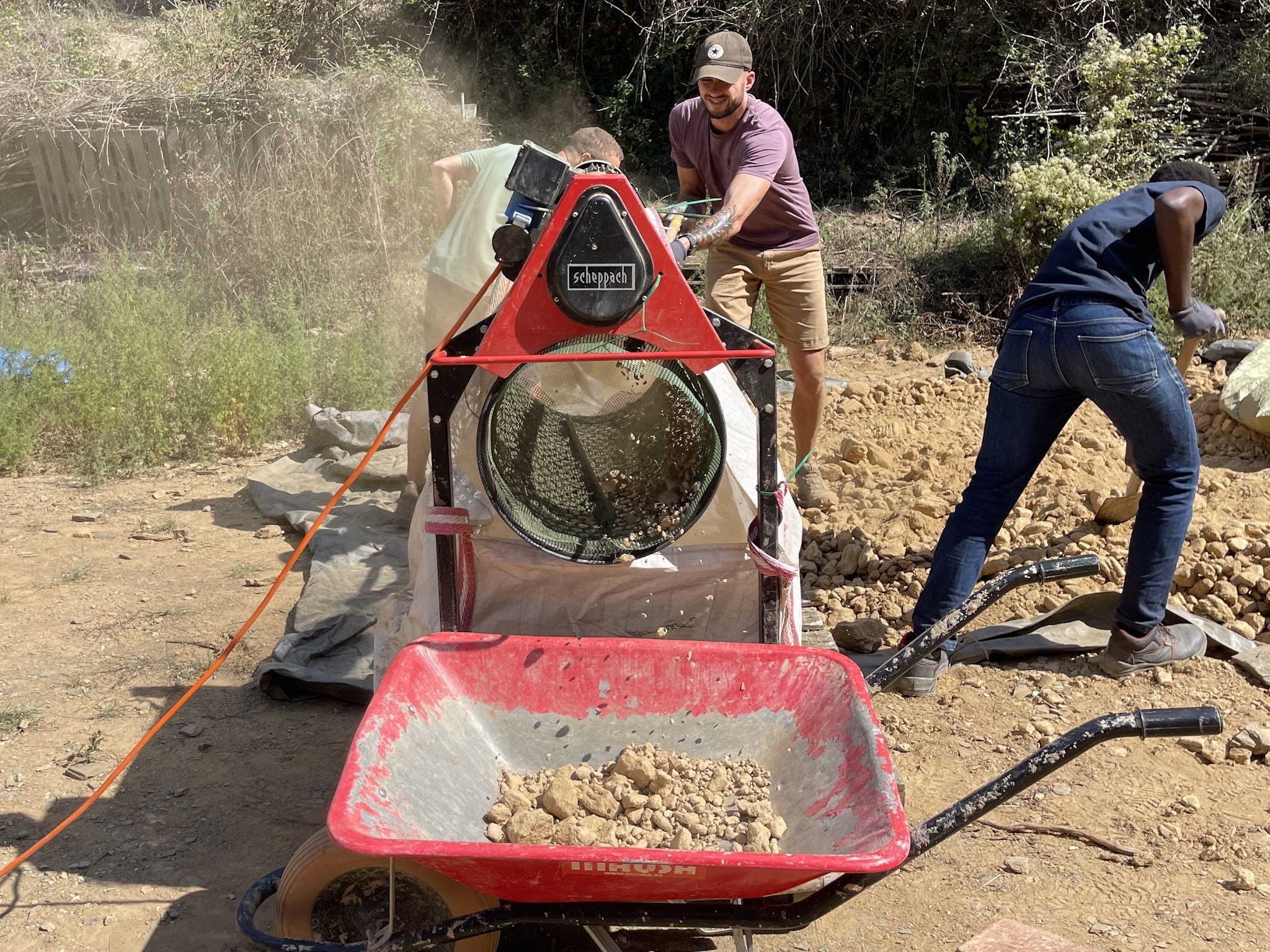
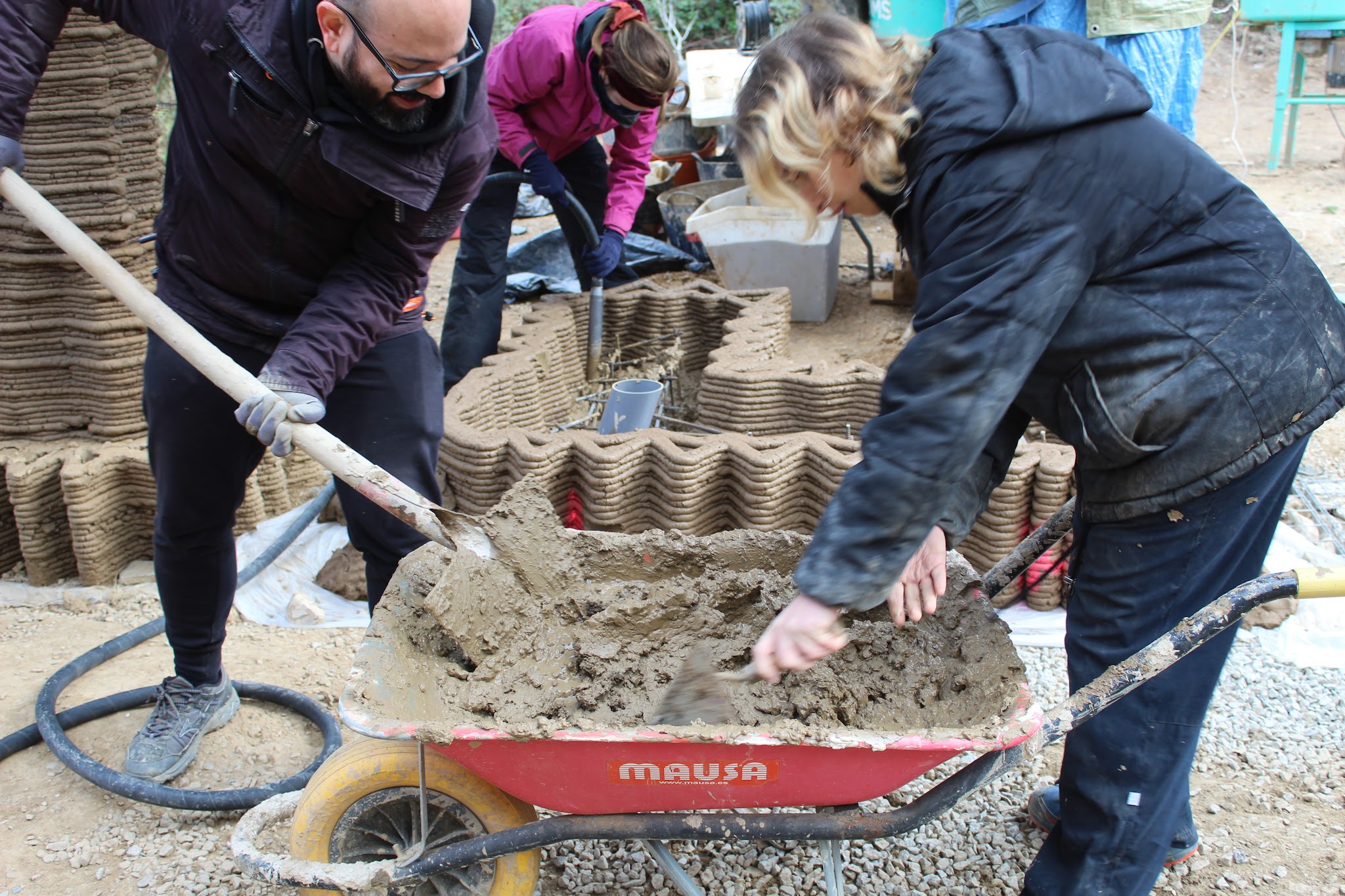
Sifting: The soil used for printing is sourced directly from the site itself. After a simple filtration process to remove larger impurities, it is then reserved for use.
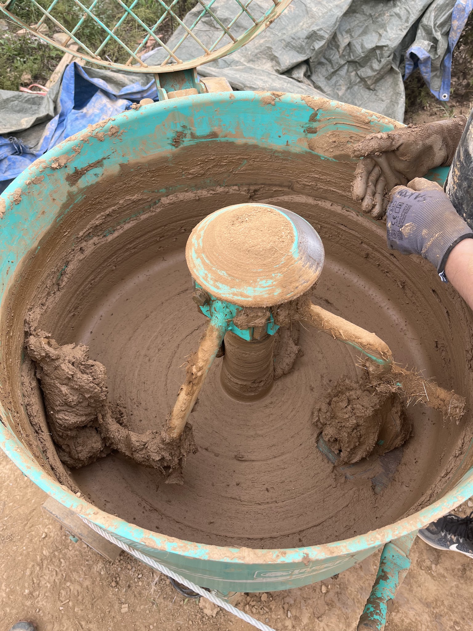
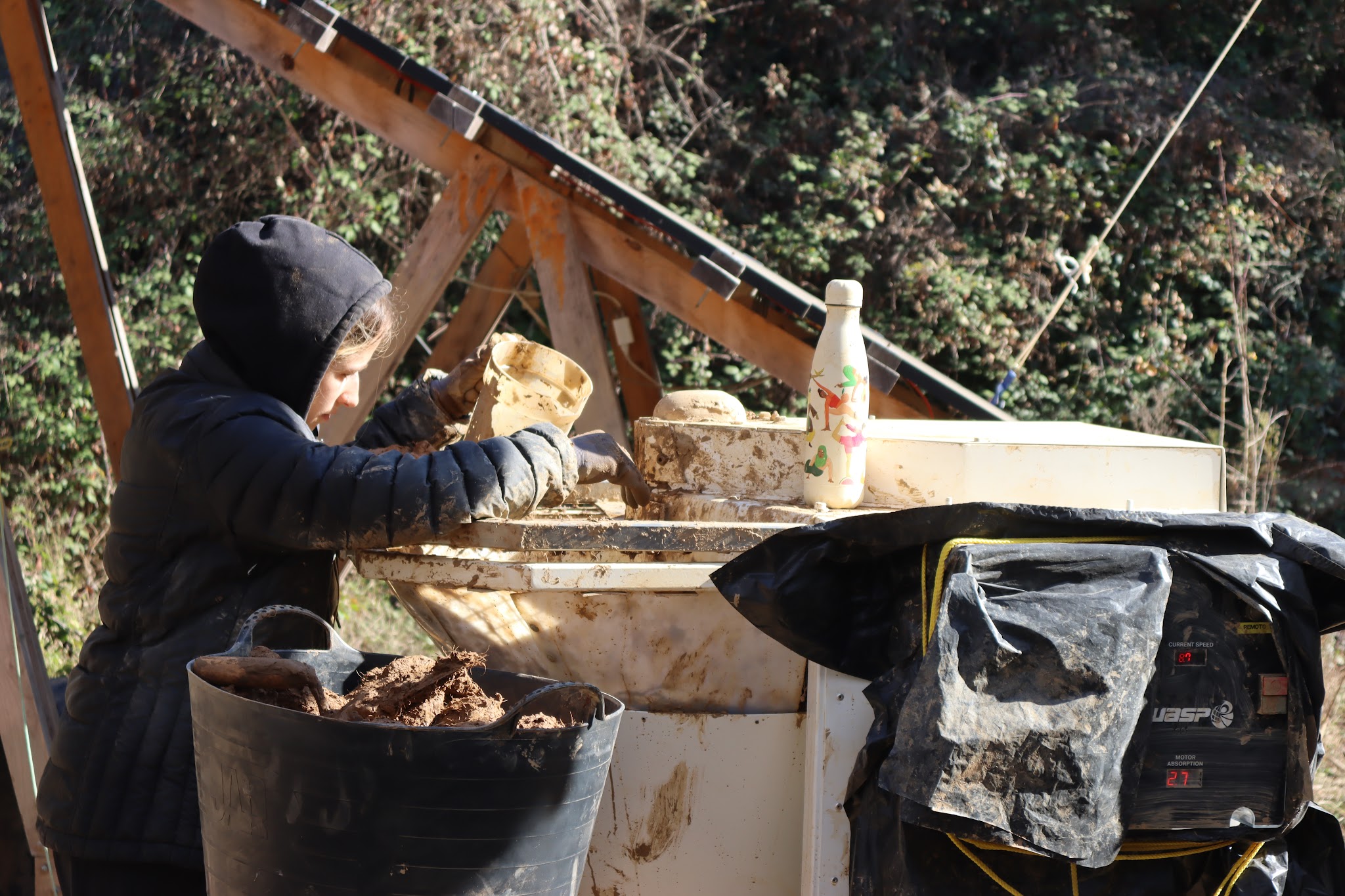
Mixing: By mixing soil in proportions of 30kg, water 5kg, sisal fiber 60g, and enzyme 9ml, a suitable soil mixture for 3D printing can be obtained.
Pumping: Continuously feed the prepared soil into the pump, coordinating with the operator to open or close the pump as needed.
B. Construction phases
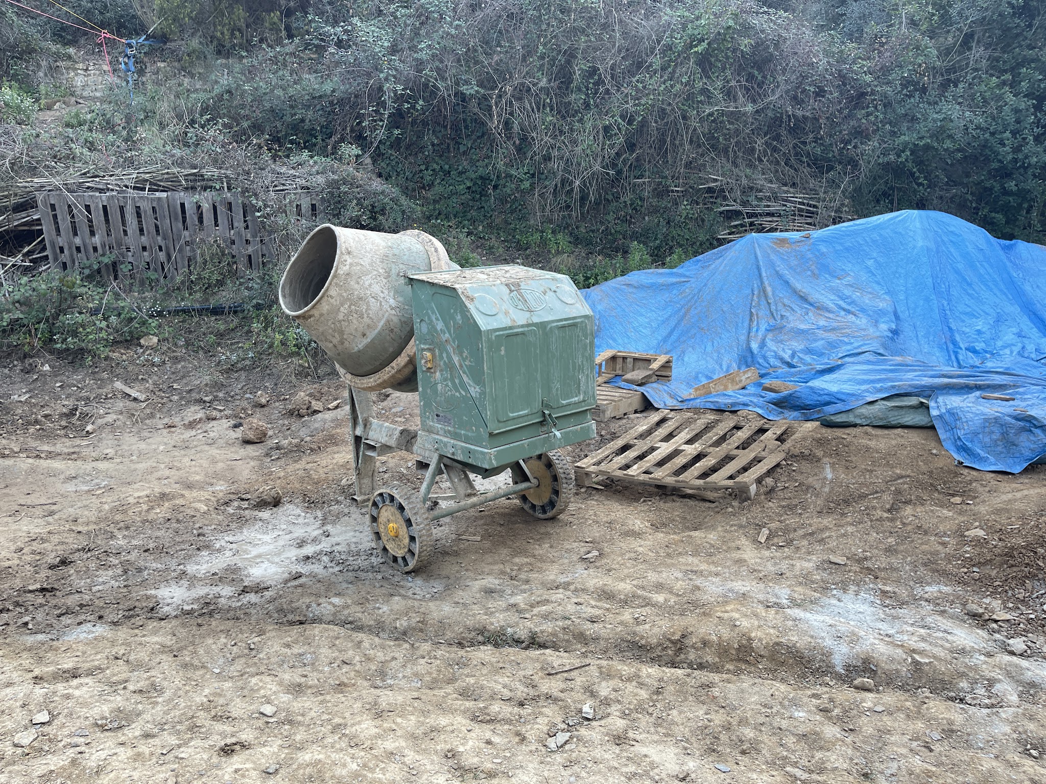
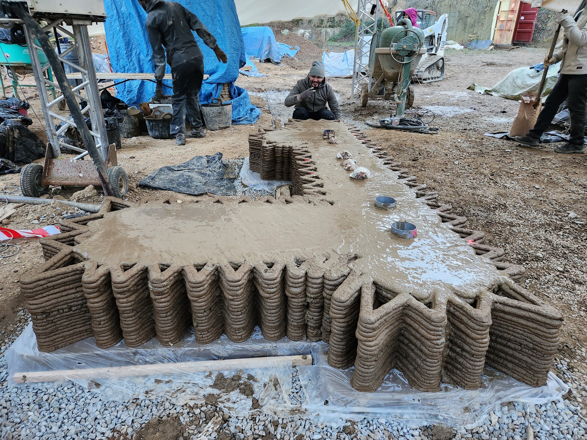
Concrete Mixing: The first 20 layers of the 3D printed wall(approx 30cm high) will be poured with geopolymer as a plinth.
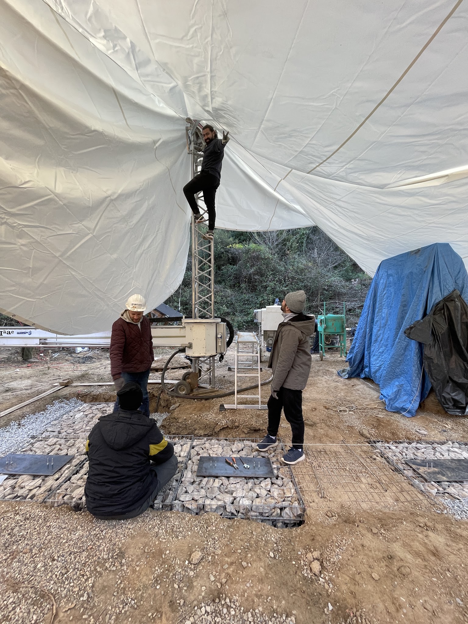
Excavation Foundation: Use an excavator to clear the foundation pit containing the buried gabion.
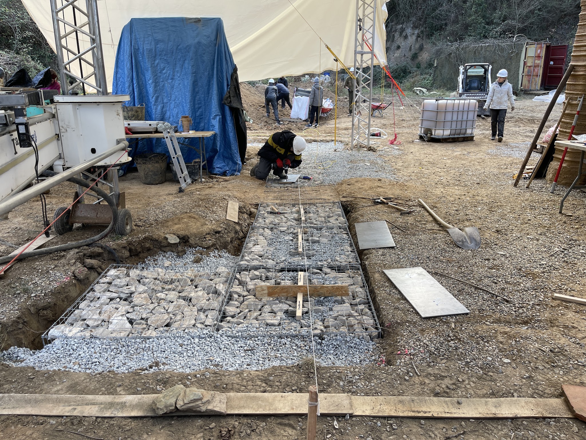
Place Gabion: The gabions are placed along the axis of the walls, they have stones inside and will be the foundation for the walls.
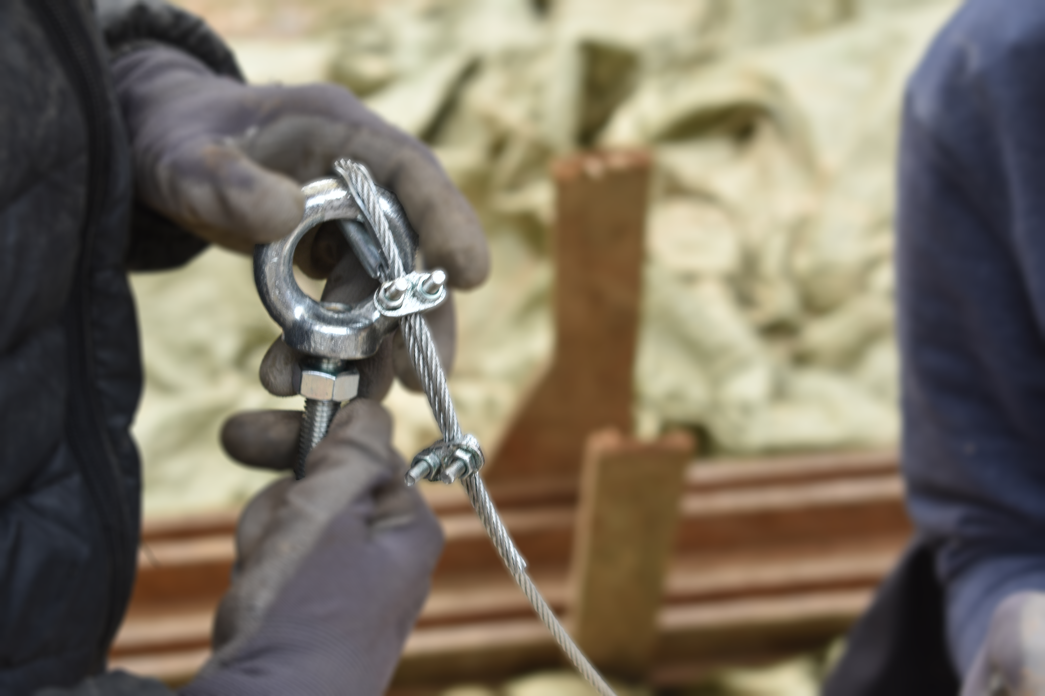
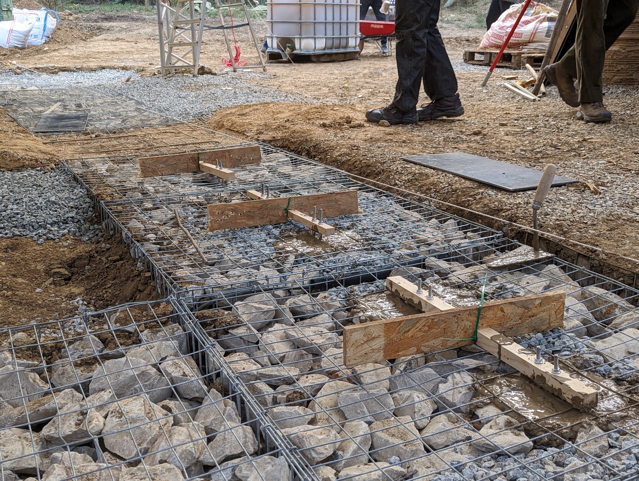
Connect U-bolt with Gabions Anchor: Place a U-bolt to connect with the anchor of the gabions and use a temporary wood stick to maintain the location.
Formwork For Leveling: Print a formwork for the leveling to make sure the walls have the same start print height.
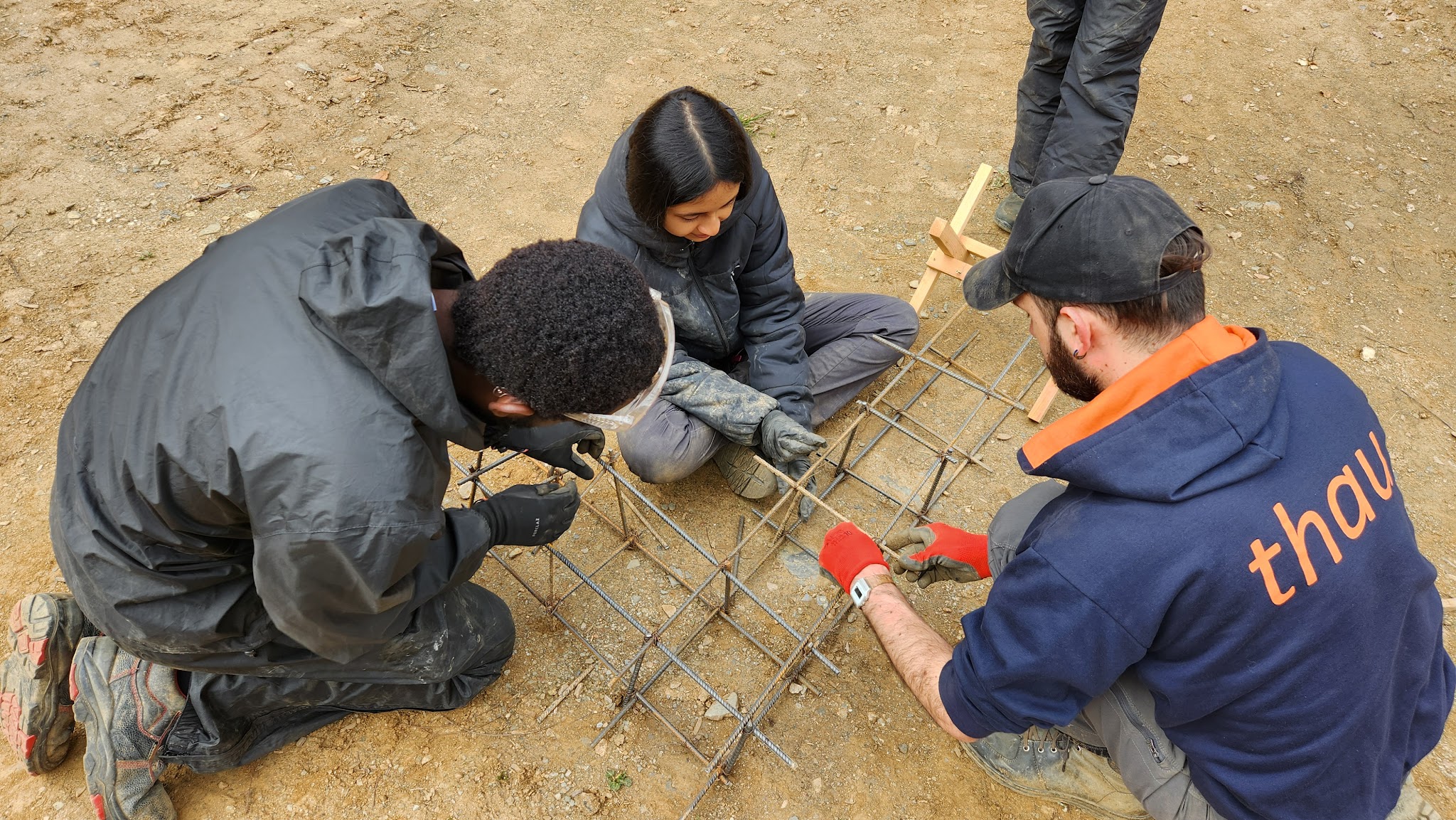
Rebar For the Leveling: Placing steel reinforcement within the formwork at specific intervals helps effectively prevent cracking.
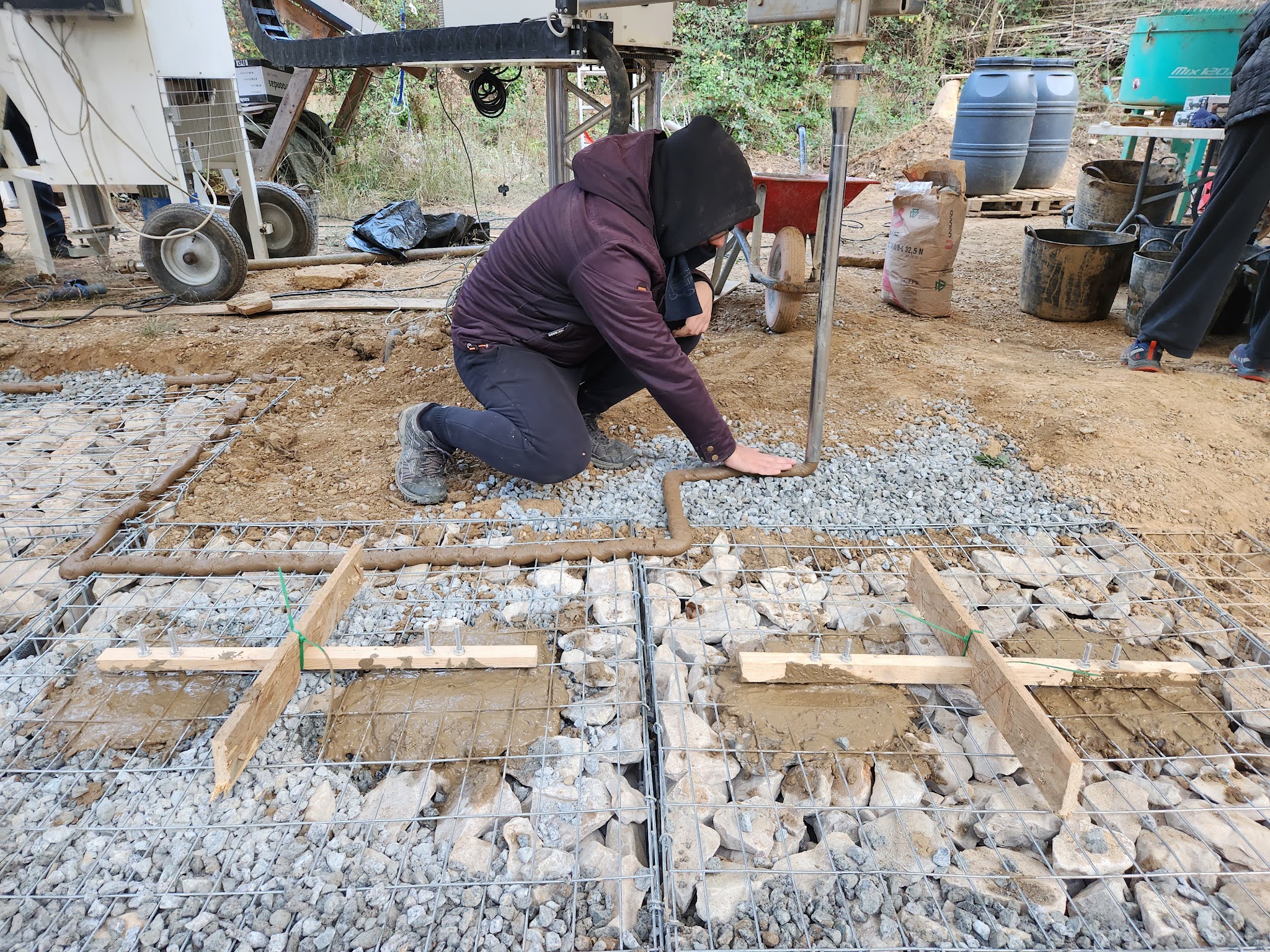
Pouring the Leveling: U-bolt is connected the cables in the gabion, and pouring with leveling.
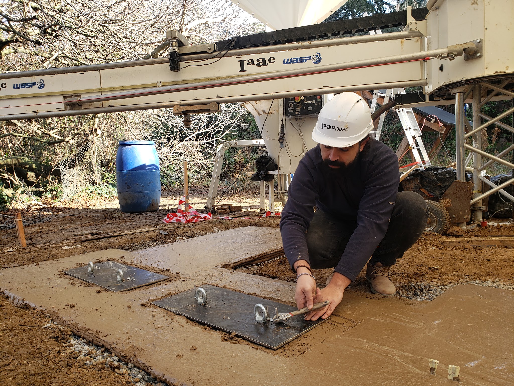
Place Steel Plate: Connect the steel plate with the U-bolt. Install an eye-bolt on the front of the steel plate to facilitate future cable connections.
Print the Plinth Formwork: Print the formwork for the plinth. Triangular-shaped supports effectively maintain the formwork’s shape, ensuring the stability of the foundation.
Prepare the Steel Reinforcement Framework: Prepare the reinforcement framework for the plinth.
Place Prefabricated Protective Cable Conduits: Place the prefabricated conduits for protecting the cables.
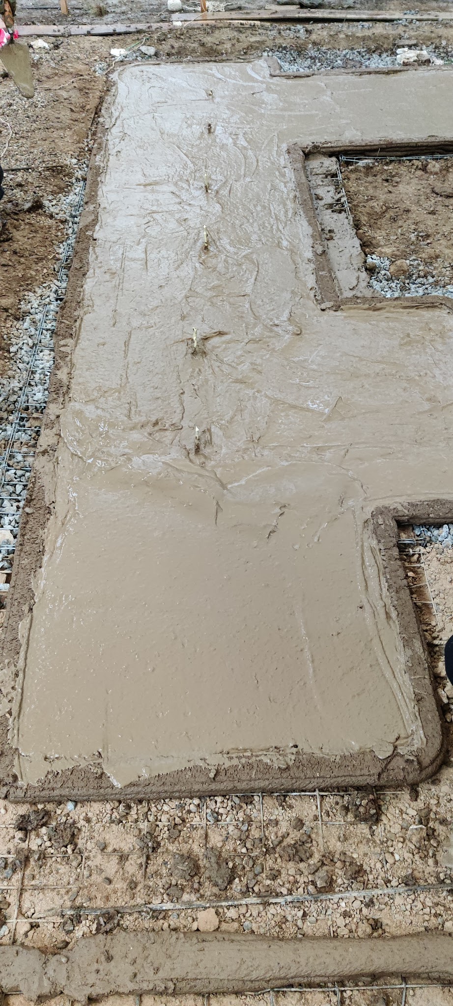
Pouring the Plinth: Pouring geopolymer into the framework to make the foundation of the walls.
Leveling the Plinth: Using tools to smooth the geopolymer, ensuring that the leveling layer is as even as possible to serve as the base for the printing walls.
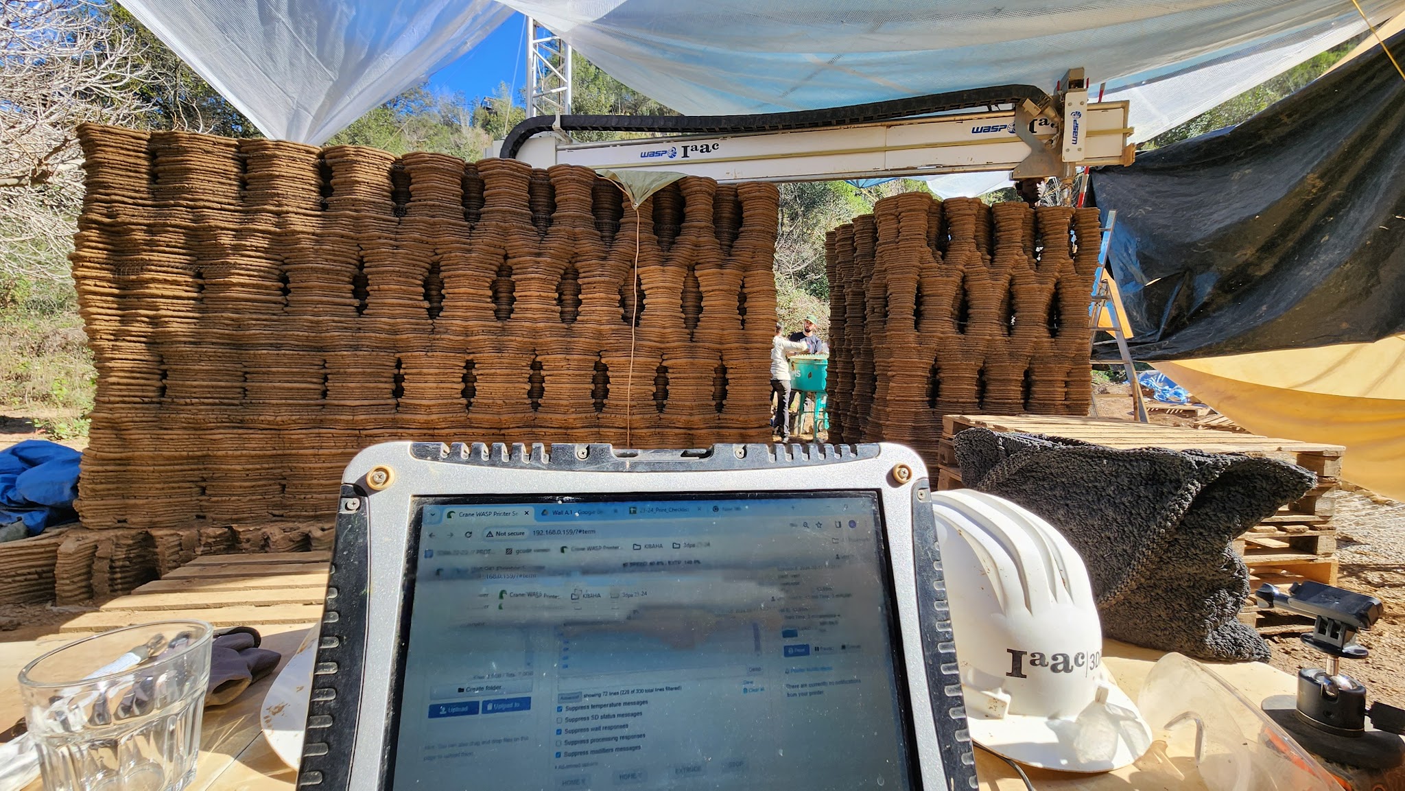
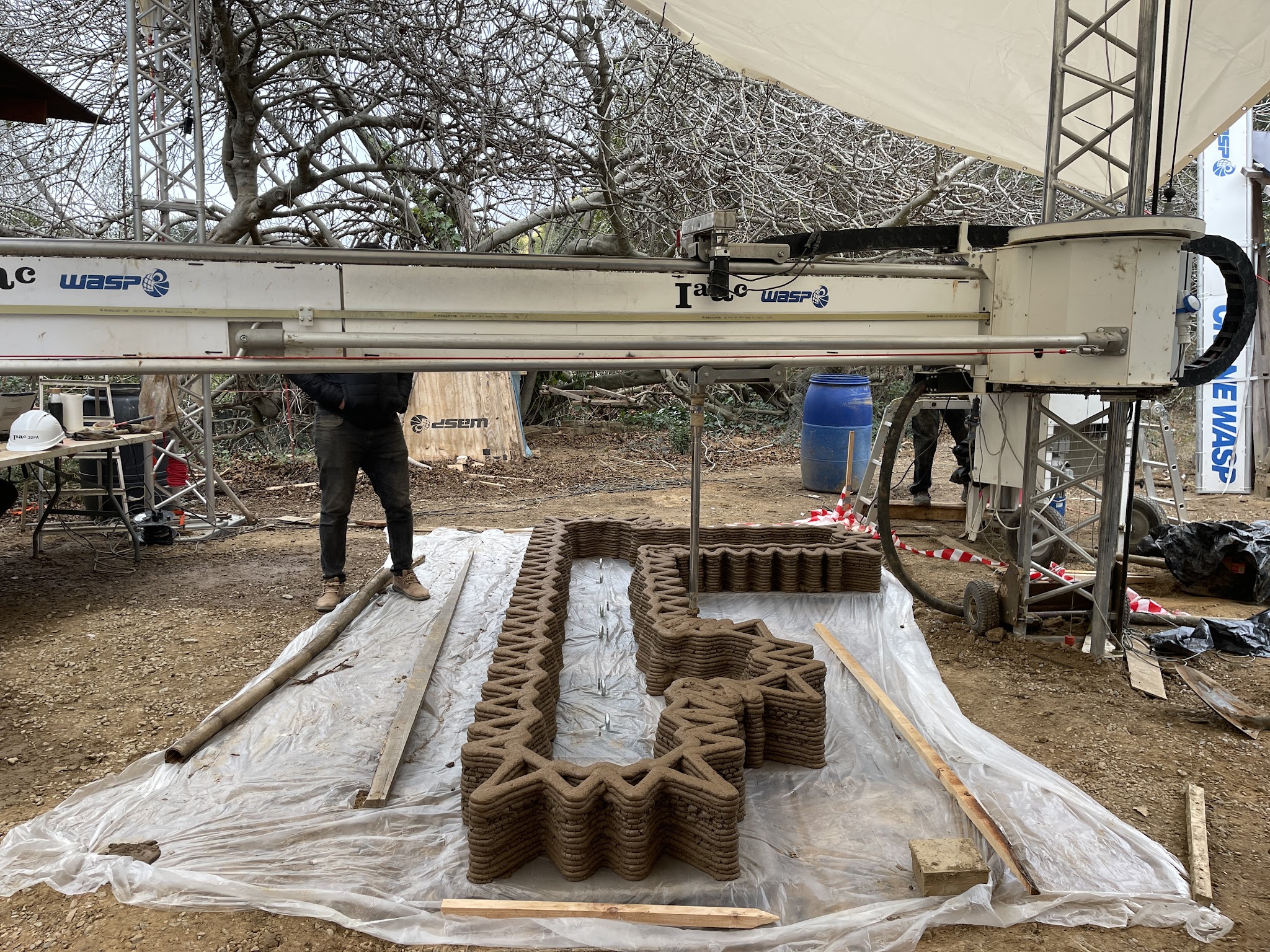
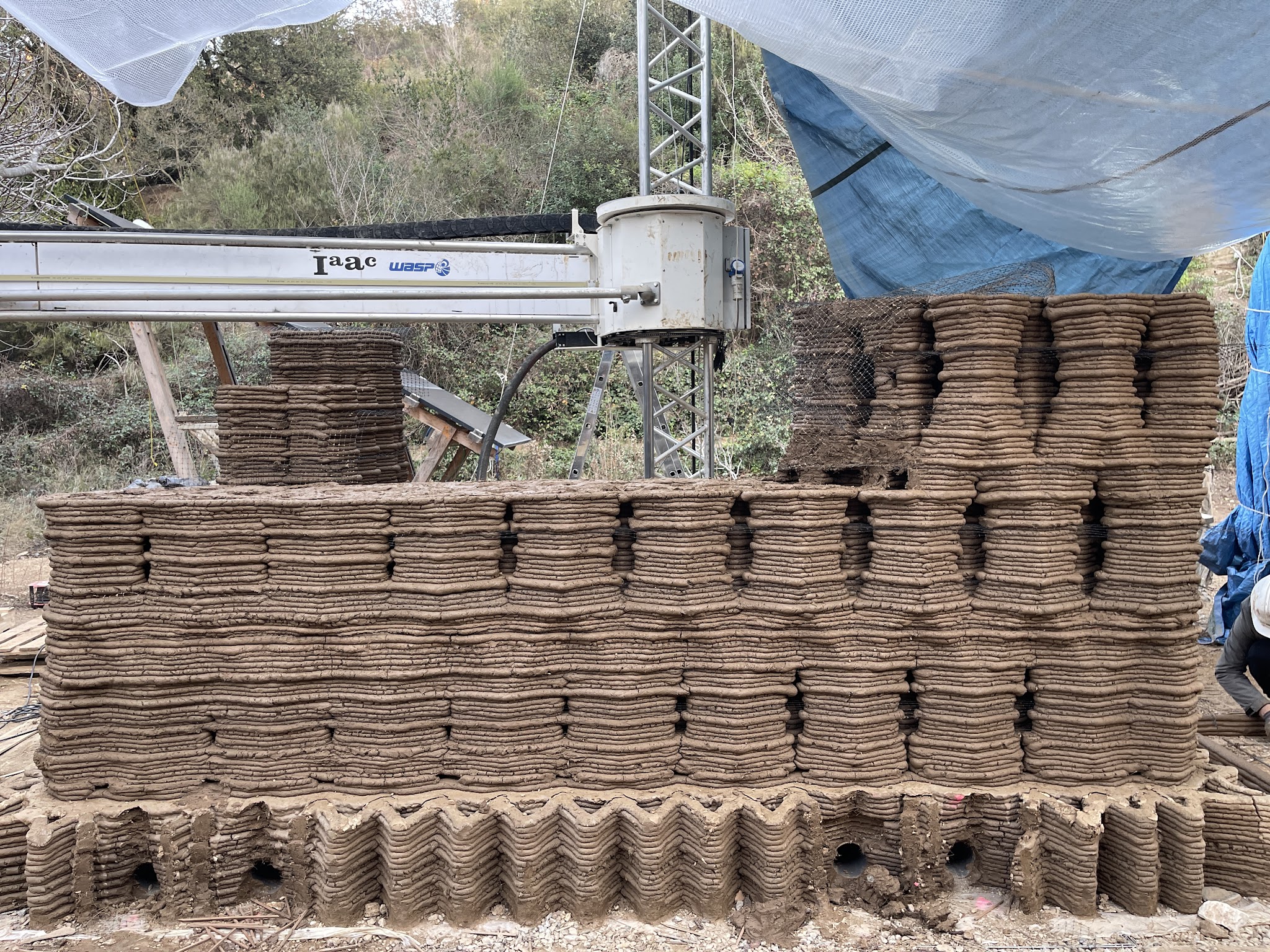
Wall Printing: Print the main body of the walls.
Level Calibrate: Real-time monitoring to ensure the horizontal alignment of the printing walls. Adjusting the crane’s center of gravity is employed to fine-tune the printing plane’s inclination, aiming to minimize any potential tilting of the walls.
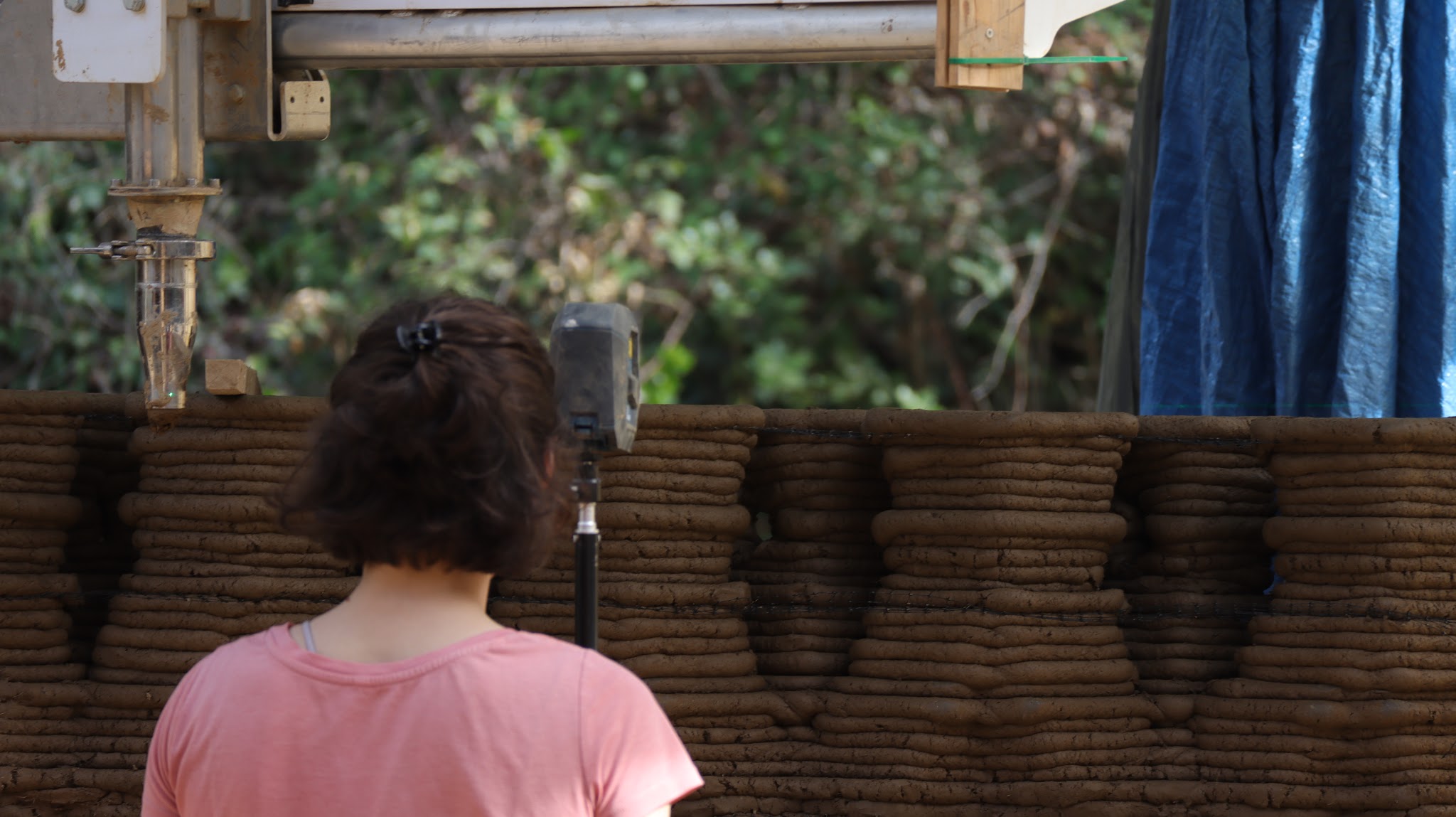
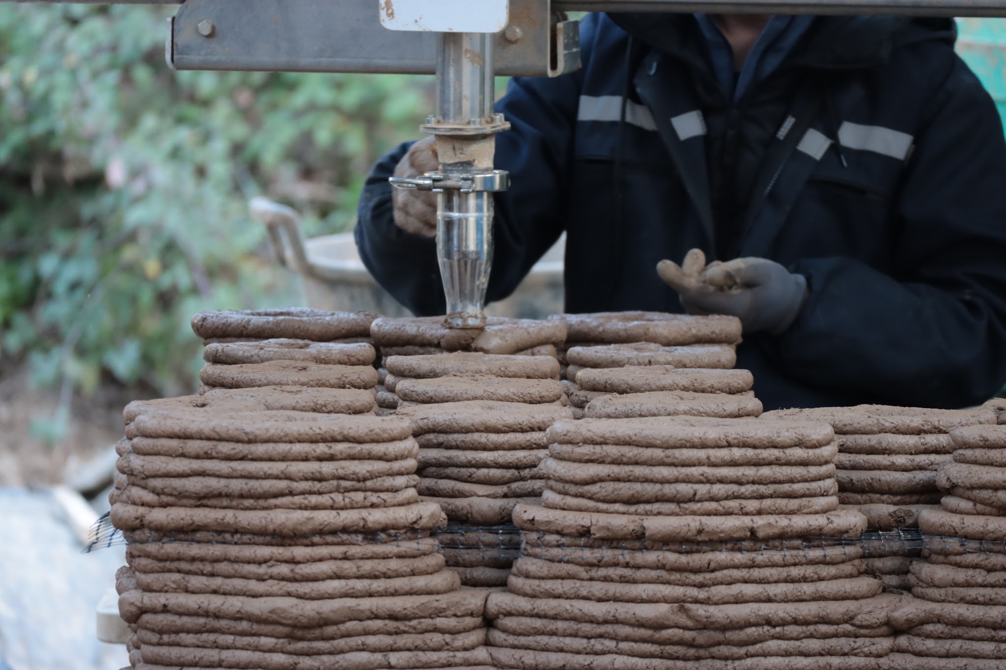
Nozzle: The person who works on the nozzle needs to monitor the quality of the extrusion, If the earth is too dry it will appear crack on the surface, if it is too wet, it will become too liquid and hard to keep the shape. Pump need to adjust the material based on the observation of nozzle operator, add more water or add some dryer material inside. And the same time, nozzle operator need to communicate with computer operator to control the speed of crane and extradition of the nozzle.
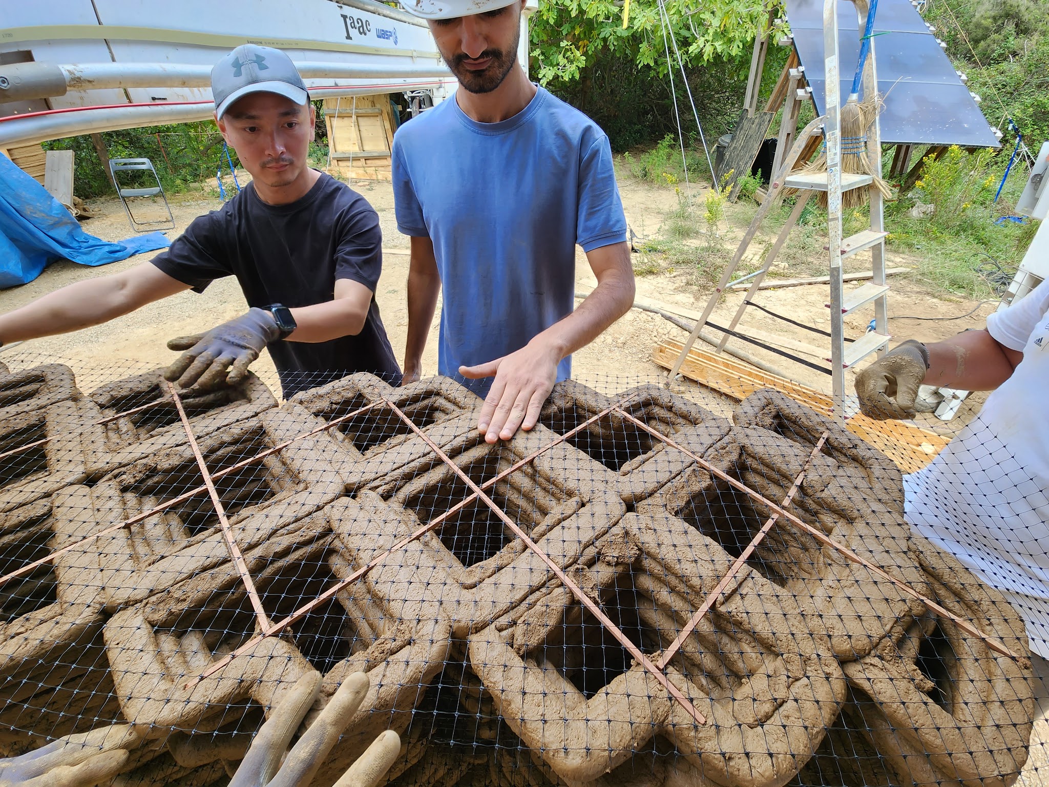
Place Sticker: Because of the complex design itself, some places will print in the air. To solve this problem, we chose to put some stickers manually based on where the next layer being printed.
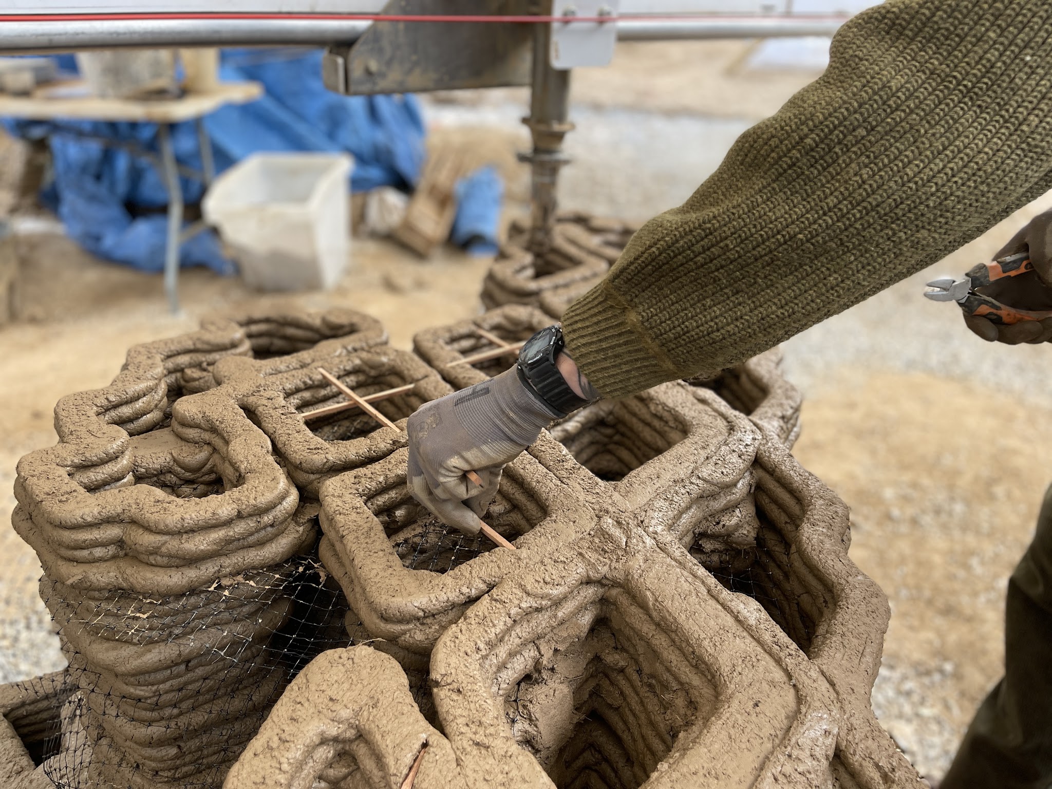
Place Mesh: Because of the complex design and lots of cavities on the wall. We use mesh to strengthen the printed wall during the wet stage. At least two meshes are placed every one period.
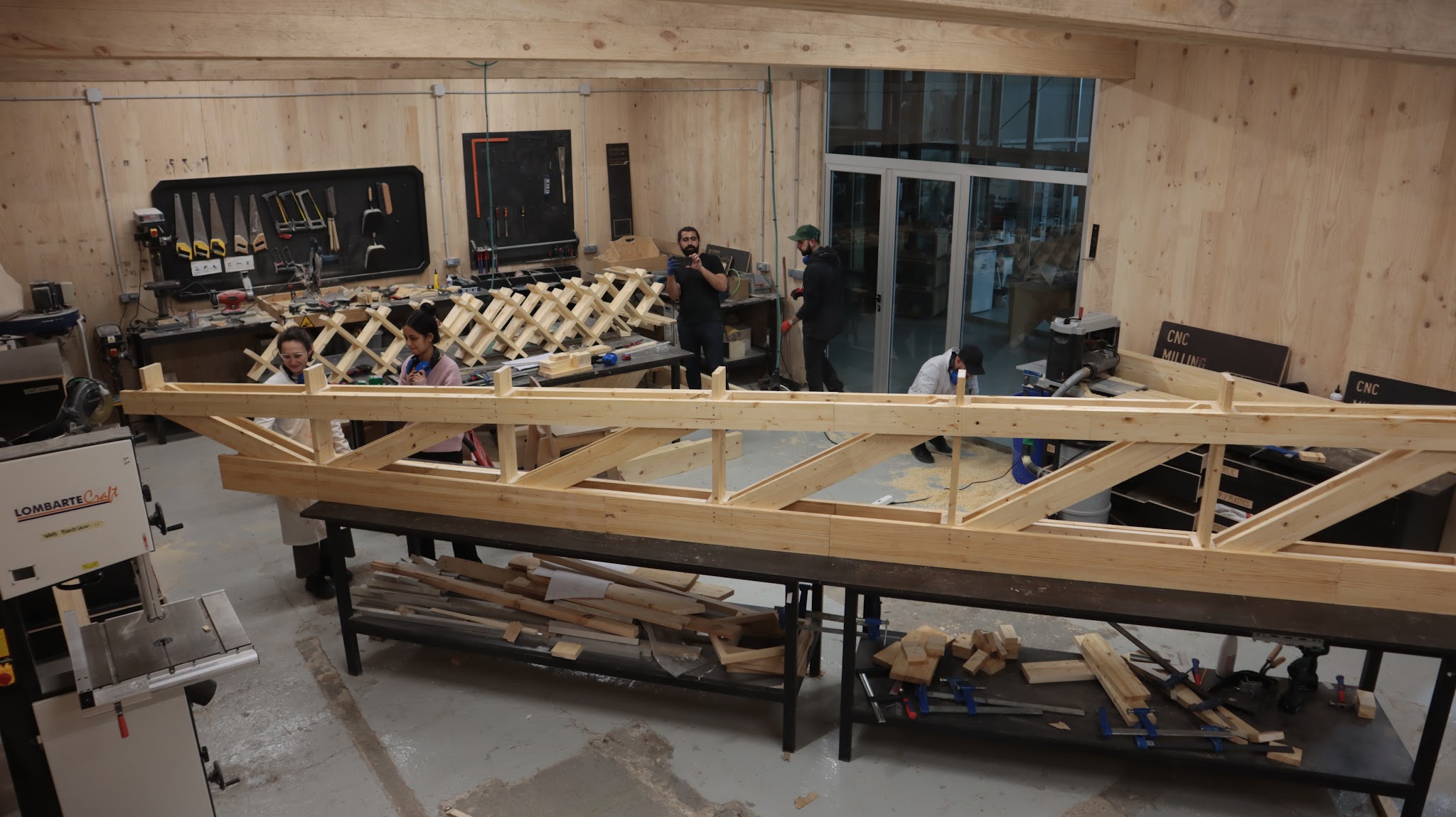
C. Pre-fabricated Wooden Roof
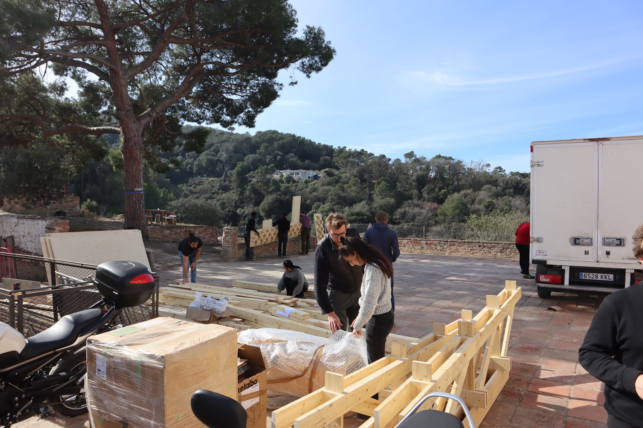
The prototype consists of 3D-printed walls and wooden structures. All wooden components are pre-fabricated ,tested and pre-assembled at the IAAC’s Fab Lab.
When all components done, they are transported to Valldaura Labs and manually conveyed to the construction site for final assembly.
The process initiated with defining the roof axis A (primary truss) and B (columns). Overall the roof consists of 3 main parts:
Distribution Plate system integrated into the wall: The aim is to equally distribute the loads of the roof into our structure
Main Beam and Primary Truss : The main beams distributes the loads onto the plates and also is splited between the to walls with the aim to be bridged while allowing certain tolerances when the walls are dry and on the same height, due to the different printing timelines. Same applies to the primary truss
Secondary Truss and Columns: The Secondary truss carries the main surface of the roof. The columns on the back of the on the secondary truss have a lift up and adaptable mechanism to changes that can occur in the matrix.
D. Wall A Printing Day 7
In the course of our journey, a wall collapse occurred. Part of the still-wet earth dropped out, and a big hole appeared in the back of the wall. Thankfully, the use of the mesh minimized the extent of the damage.
Even if a conclusive reason for this accident remains unknown, we can at least speculate that it was partially our cadence of printing on a wet-state material.
This situation forced us to pivot quickly in order for us to respond to this emergency.
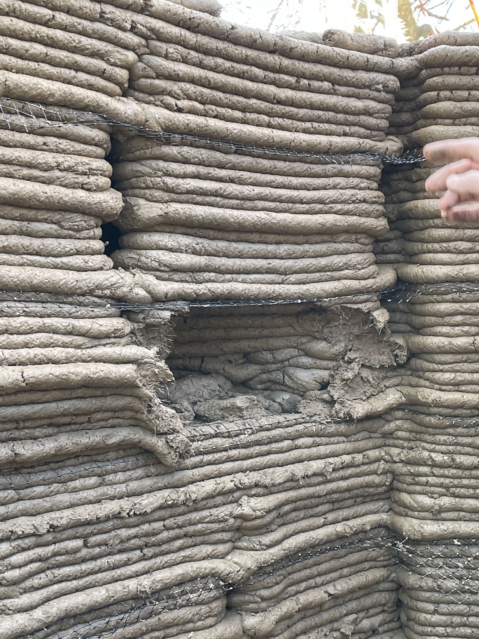
We filled the hole with earth to support the upper part and leaned up woods boards to help support the whole wall, avoiding any further damage.
We returned to the site three days after the collapse to let the structure dry and also to allow the deformation to occur. Luckily the deformation only happened in certain areas, and the major parts of the wall could be kept.
According to our on-site evaluation and group discussion, we decide to remove a maximum of 35 layers (approx 52.5 cm high) from the wall. The north buttress which is the window area is quite separate from the main wall, so we kept that part intact. The Southern portion of the wall is also well supported by the South buttress and didn’t deform at all, so we kept that portion intact as well..
It took about half a day to remove material from all the affected parts.
Since Wall A collapsed, we were confronted with two primary challenges.
Regarding the removed section, our challenge lay in preparing the G-code solely for the removed parts and manually rectifying the gap between the old and new segments.
The other obstacle stemmed from shrinkage induced by the printing process being interrupted by the collapse. Upon completing the printing of the removed segment and returning to the level where we previously halted, we had to adjust the digital
model to facilitate a gradual transition from the shrinkage layer back to the original shape.
In response to the situation, modifications were made to Wall B to shorten its length, thus saving time. Given its location within the same crane area as Wall A, printing could proceed without relocating the crane. These adjustments were imperative to ensure adherence to our schedule for completing the print.
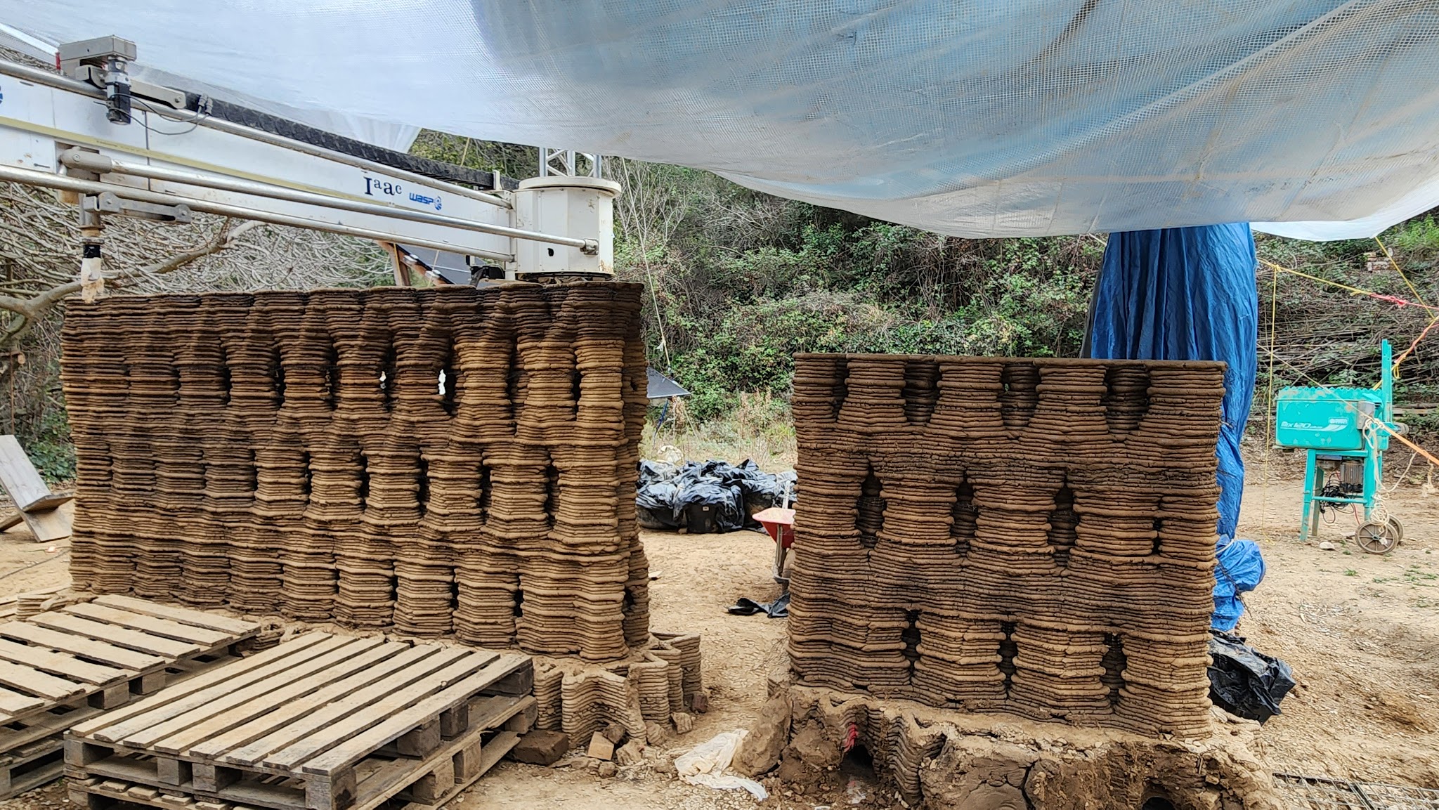
Final Prototype
3dpa 2023/2024 credits
Directors Edouard Cabay, Alexandre Dubor
Coordinator Yara Tayoun
Faculty Oriol Carrasco, Elisabetta Carnevale, Alicia Huguet
Faculty Assistants Secil Afsar, Nestor Beguin
Collaborators Colette, philanthropic organization ; 3D WASP, Large Scale 3D printing ; SOCOTEC, Structural Consultant ; Hassell Studio, Architecture Consultant ; Vervictech, Enzymes provider
Researchers Jose Antonio Gutierrez Rangel, Joseph Milad Wadie Naguib, Justin Hanlon, M´Hamed Alila, Maria Kaltsa, Mark Francis, Noel Akroma, Sakshi Pawar, Sara Ayoub, Vesela Tabakova, Yang Xiao
