In addition to the design task set out as part of this semesters studio brief, we were tasked with a pioneering project: to develop innovative workflows facilitating collaboration across various software platforms. We started this process by producing a collaborative workflow diagram of our expected tasks and distribution of work across perceived disciplines. This can be seen below.
Initial workflow diagram
Tasks were divided into three roles; The architect, Computational designer (C D) and the BIM Technician. The supposed workflow would arrange itself in 5 work stages, aligning with the RIBA plan of work and ending at construction hand over (The pin up). Working to this format would allow us to extract information at each stage, capturing snap shots of the project as it progressed in its LOD and storing them in the CDE in a range of data formats (PDF, DWG, RFA).
Amended workflow diagram – red highlights the main changes
In reality, the workflow diverged slightly; however, the structure remained largely consistent. The main changes happening between stages 03 and 04, owing in large part due to the project not making it past the review stage between stages. This ultimately led to a fundamental change in the design of the project and required reviews of both design and practice. The main variations are discussed below.
Design – The expectation was that there would be various designs for accommodation pods; however, this was largely rationalised to align with the project narrative, which significantly altered the workload. It was discovered that designing the mine shafts and tunnels proved more labour-intensive than initially anticipated. Consequently, focus shifted towards developing a Grasshopper definition to streamline the process.
Workflow – It was expected that the majority of geometry transfers would occur through Speckle connections. However, due to accessibility issues, Rhino.inside emerged as the primary method of transfer. Nonetheless, Speckle continued to be utilised for transferring geometry to the studio stream and as part of the automation task.
Work Stage Development
In this next section, we will discuss the development of the project at different work stages and the specific challenges presented. As the team were not involved in the development of the brief, we will not be covering stage 00.
Stage 01 – The aim for this stage of the project was to develop the narrative and and send our desired project location to the MaCAD speckle stream. This was largely successful. For the narrative, a opening statement was crafted which guided the project through the work stages and our site sent as a sphere which can be seen below.
In the not-so-distant future, humanity’s ambitions have transcended the bounds of Earth. Enter Red Horizon Resources, a daring venture to forge habitable sanctuaries amidst the towering cliffs of the Martian landscape. Employing an avant-garde computational methodology rooted in aggregation, we delve into the enigmatic depths of Martian regolith, unlocking its secrets to harness potential construction materials and precious metals. Our mission? To cultivate sustainable habitats that defy the desolation of the Red Planet. Welcome to the new frontier.
Site selection sent to speckle
Stage 02 – At the end of this stage we were hoping to have completed the module types, their adjacencies and the initial site model. Pod types were modeled at LOD 100 in Rhino at this stage and initial aggregations were produced using WASP and grasshopper. These were then pushed to Revit with site information via Rhino.Inside which provided the anticipated output.
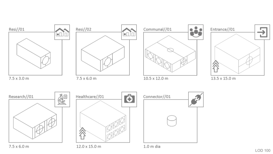
Initial pod massing types
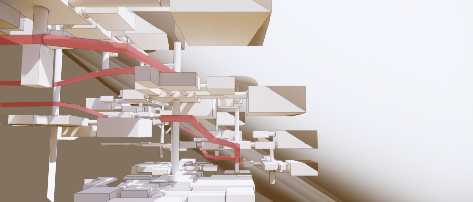
Combined model at LOD 100
Stage 03 – By the end of this stage, our aim was to have refined the details of the existing elements while also solidifying concepts for the mining networks and camps. However, as mentioned earlier, the project’s direction shifted at this juncture, prioritising the development of a robust system to plan the networks. This will be elaborated upon in the subsequent section, which examines the automation task.
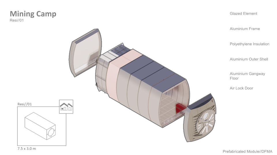
Pod developed to LOD 200
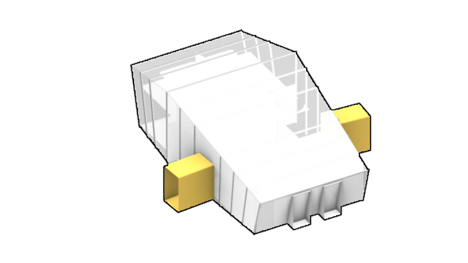
Design Change – Rationalised Pod
Stage 04 – The anticipated development would see information co-ordinated and brought up to a level of detail where schedules of material and cost could start to be associated with project elements. This would see the development of Revit models for both the wider project and the detail of the pods. Information at this stage would be moved into Revit, checked and co-ordinated and then this model would be used to produce renders using twin motion.
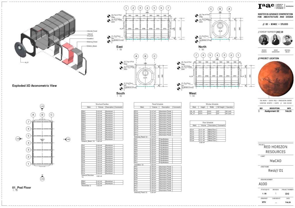
Detailed Model of initial pod design
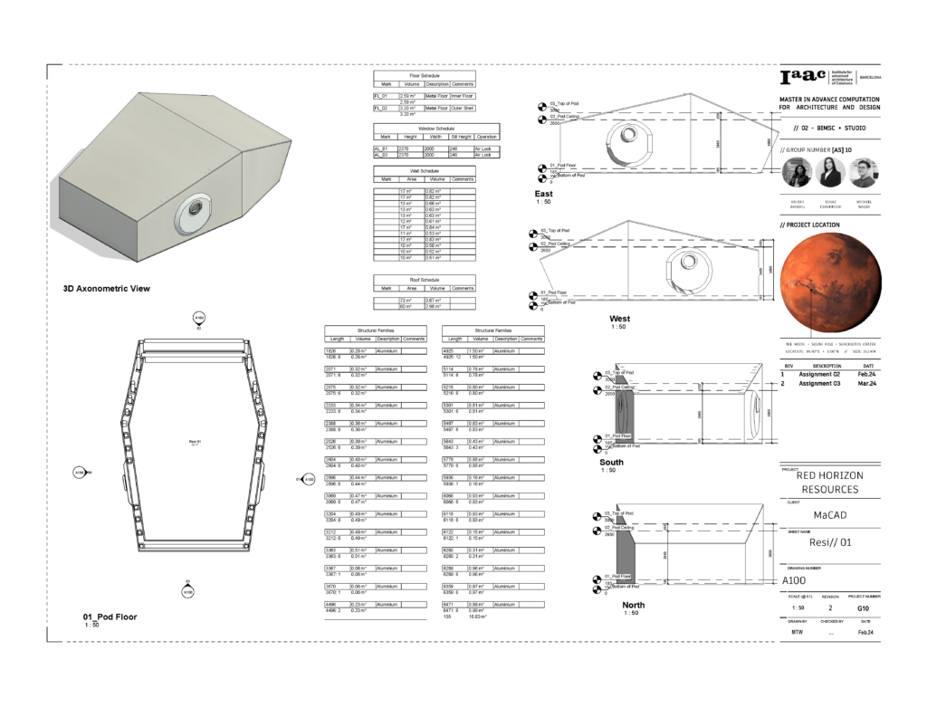
Detailed Model of rationalised pod design
Stage 05 – This stage aimed to transfer information to the MaCAD Speckle stream while also generating final visuals for the project. The project was divided into three primary layers: Site, Surface, and Mining Networks, each comprising sub-branches. This structure enabled the movement and updating of information without affecting other elements, thereby reducing upload time and facilitating a more robust approach that supported the distribution of sub-tasks. The stream can be found here.
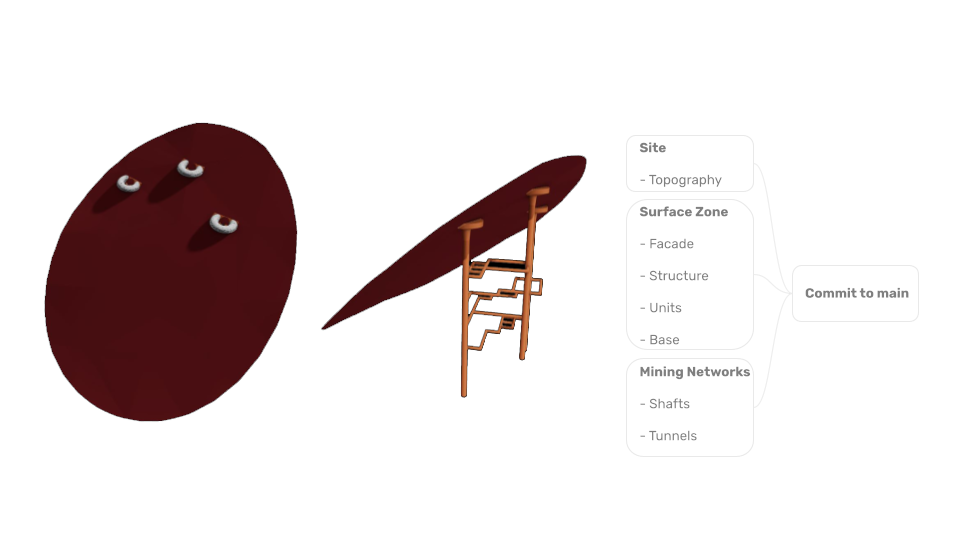
Speckle Stream
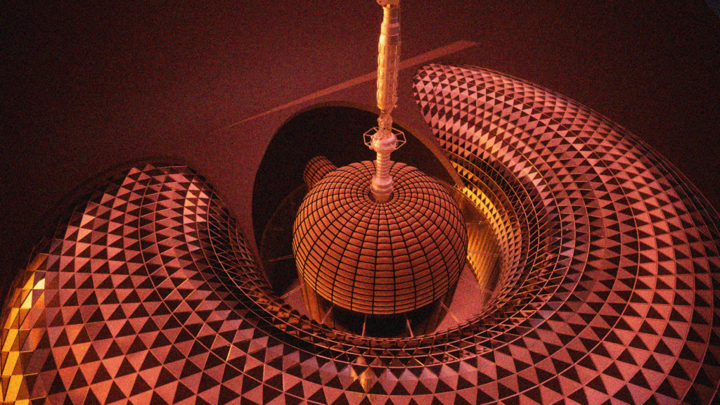
Twin Motion Visual
Automation Task
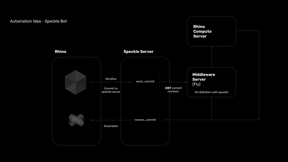
As part of the collaborative seminar, our assignment involved automating a repetitive process within our project. To accomplish this, we explored methods for assigning geometry to voxels within the mining matrix. The intention was to develop a speckle bot which could push developed geometry back into the main model.
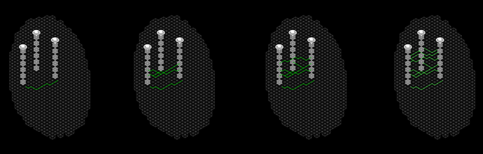
Initially, a search algorithm was developed to find the shortest path through the matrix to the vertical connection nodes. This would then provide a route through the matrix and the associated voxels as shown below.
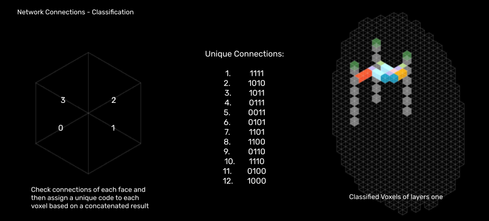
This would then allow for the classification of the voxels based on their connections and an identifier code to be assigned.
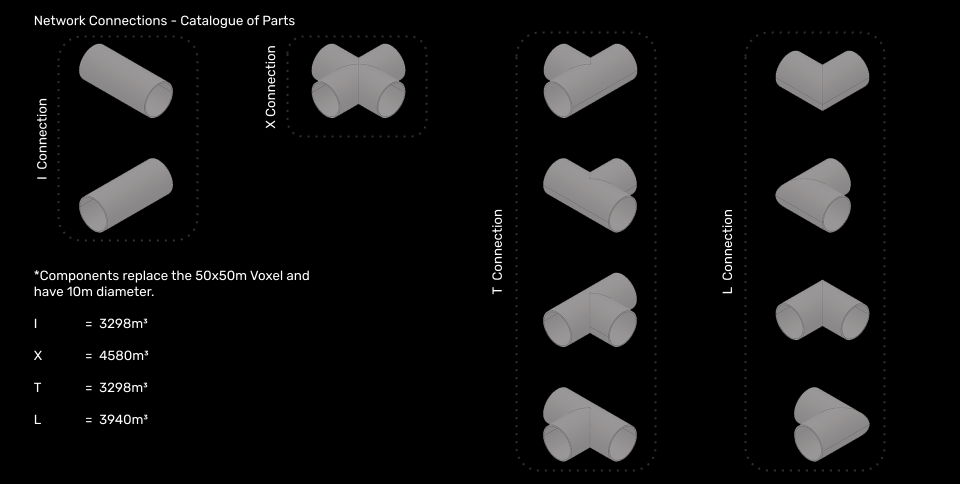
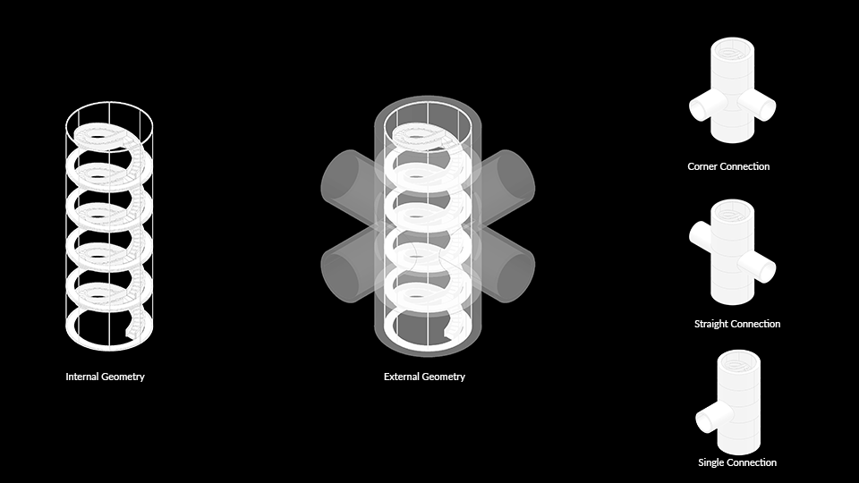
A separate script was developed to produce the required geometry inline with the dimensions of the the matrix which could be connected to and provide developed geometry.
This same process was also followed to allocate the vertical connection pieces as shown below.
The automation was then deployed successfully and the results can be seen below and are included as part of the previously mentioned speckle stream.