
Reference Project:
Our research included several realized projects that are characterized by their innovative timber constructions:
- The Centre Pompidou in Metz: known for its free-form timber constructions that speak a unique architectural language.
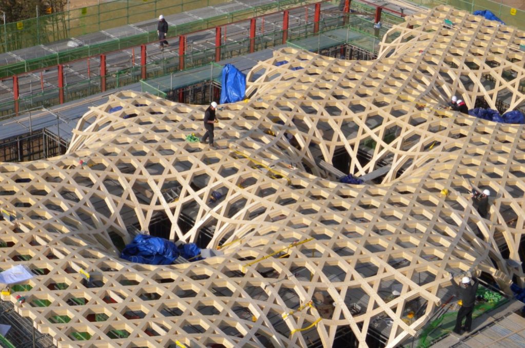
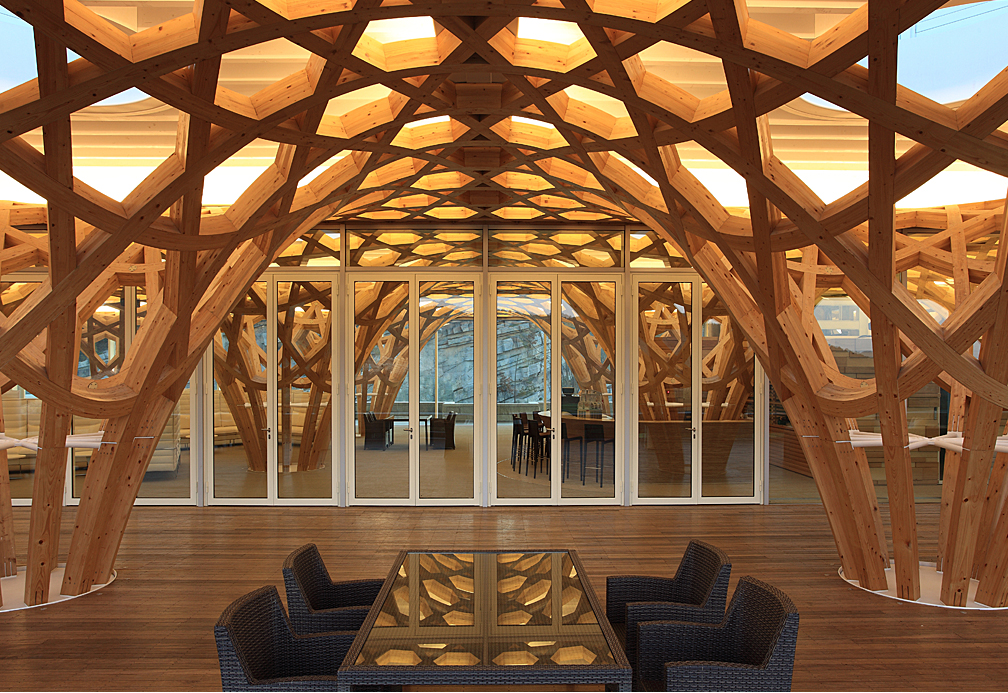
- The Central Mosque in Cambridge and the Golf Clubhouse in Haesley Nine Bridges: Both projects impressed us with their monolithic and holistic appearance. Their supporting structures consist of several wooden beams that alternately reach over and under each other at their intersections, which is reminiscent of the weaving of textiles – hence the term “Timber Weaving”.
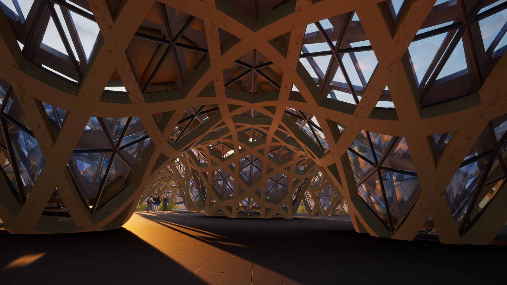
For our project we aimed to unite the monolithic integrity of the mosque and the clubhouse with the free forms of the Centre Pompidou to create a unique architectural identity.
Project Description
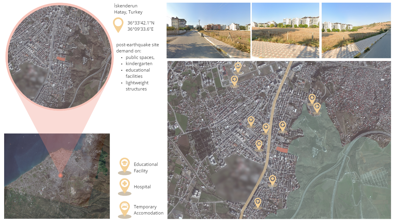
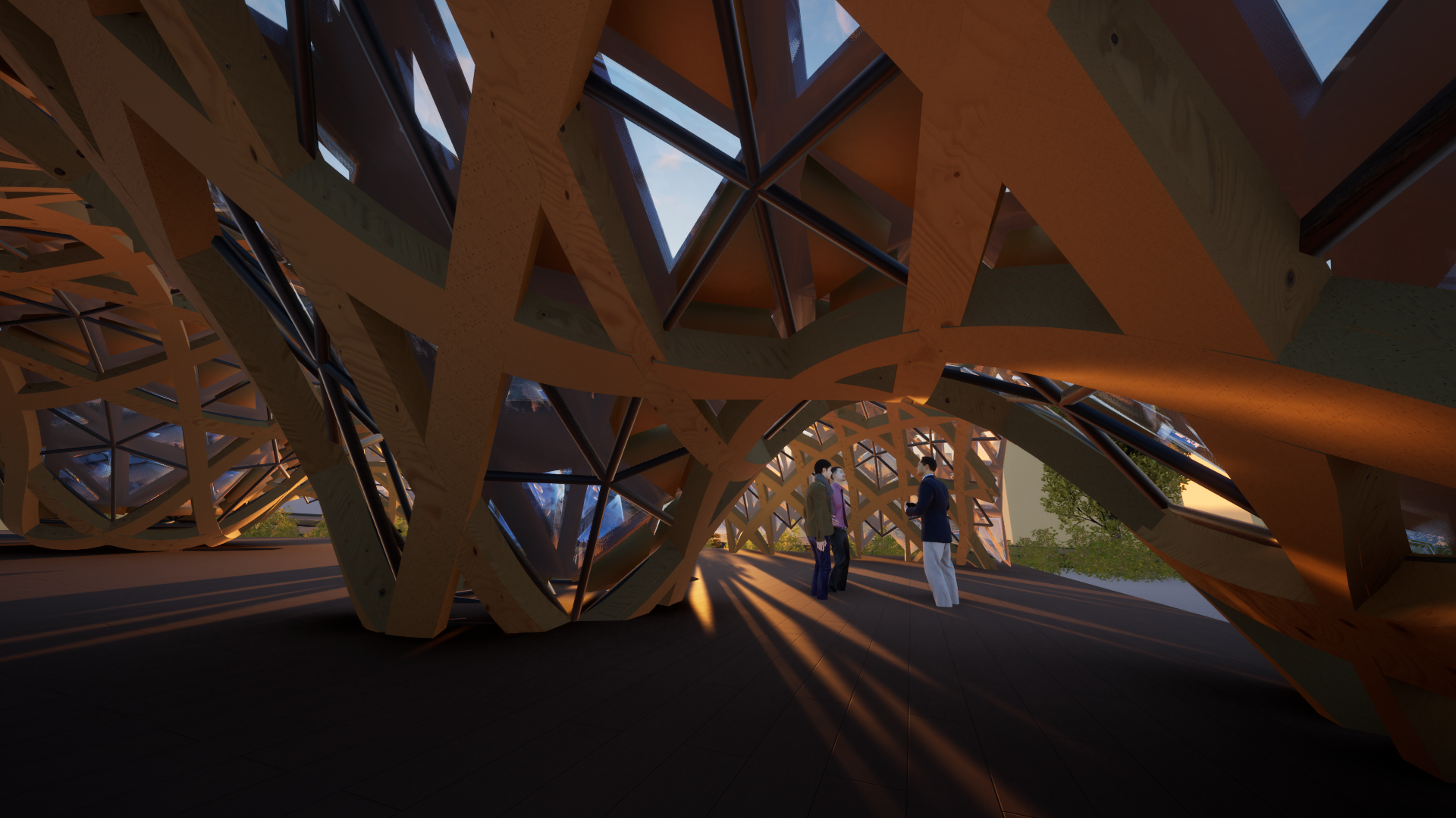
We decided on a project in ?skenderun, Turkey. This area was recently hit hard by an earthquake and we thought it would be an interesting idea to use the Timber Weaving method at this location for a Learning Center.
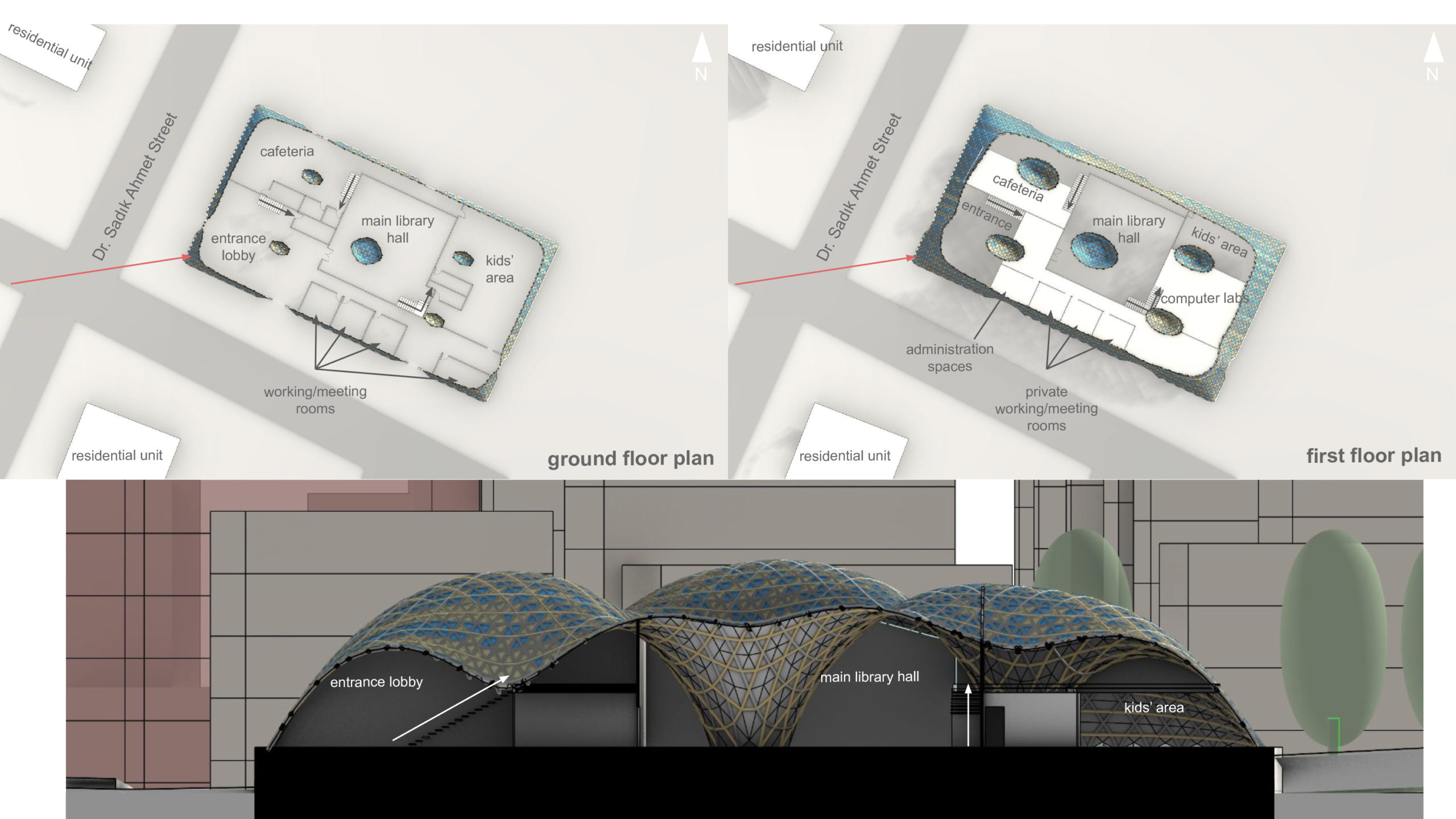
This Center includes a library, a childcare area, a café corner and several seminar rooms. This multifunctional center was designed to serve as the heart of the community, providing spaces for education, social exchange and cultural events. By combining these different functions in one building, we wanted to create a vibrant and interactive space that meets the needs of the local population.
Another aspect of our design was the resilience of the timber construction to earthquakes. With the special properties of Timber Weaving – such as flexibility, strength and the innovative connection technology – we wanted to ensure that the structure could withstand future seismic events.
Building techniques
As part of our studio course, we intensively researched the construction techniques required for our project. We would just like to mention the most important key points here:
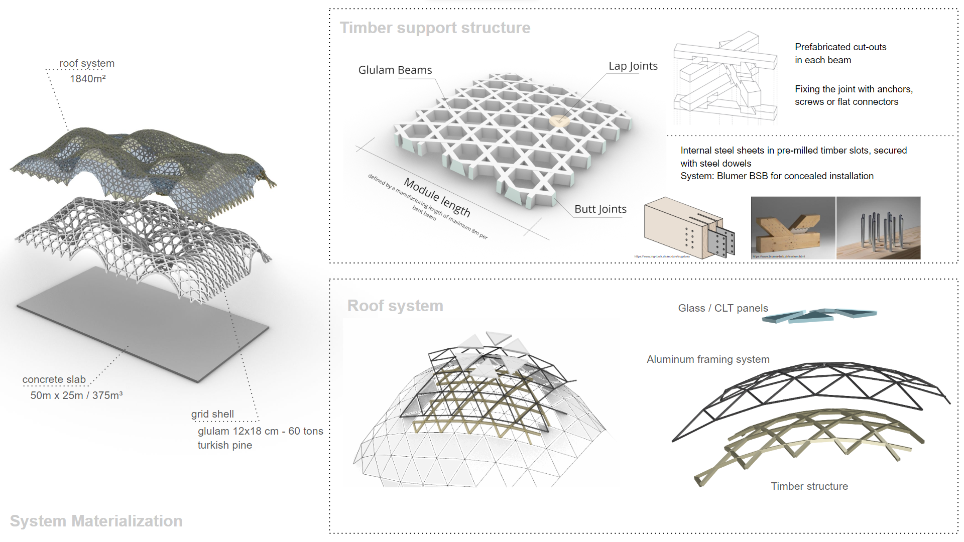
- Production of double-bent glulam beams: This is extremely material-intensive and requires a high level of expertise as well as specialized equipment. Compared to single-curved beams, which are still relatively easy to produce, numerous wooden lamelles have to be glued together for the double curvature and then milled into double-curved beams using specialized CNC machines.
- Prefabrication and assembly on the construction site: The beams are prefabricated in the factory and then transported to the construction site, where they are pre-assembled in individual segments. Each segment is lifted in with a crane and connected to other segments using butt-joint technology. The connection is made via internal perforated plates in pre-milled pockets.
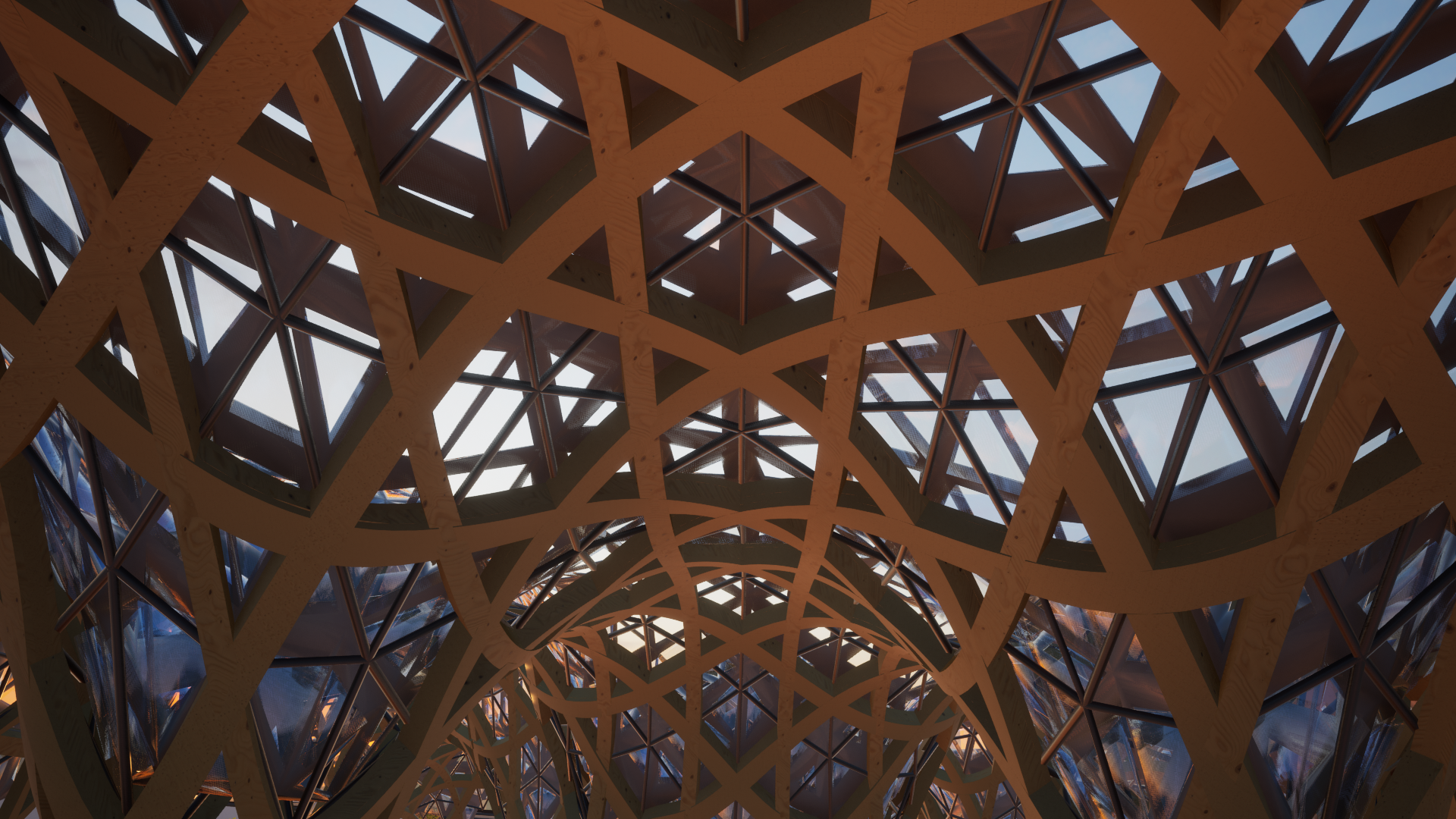
- Connection technology within the segments: The connection within a segment is made using a lap joint. Precisely fitting recesses are milled into each beam for the other beams. Our model project, Haesley Nine Bridges, used two-part beams due to fire protection requirements, an approach that we have adopted for our project.
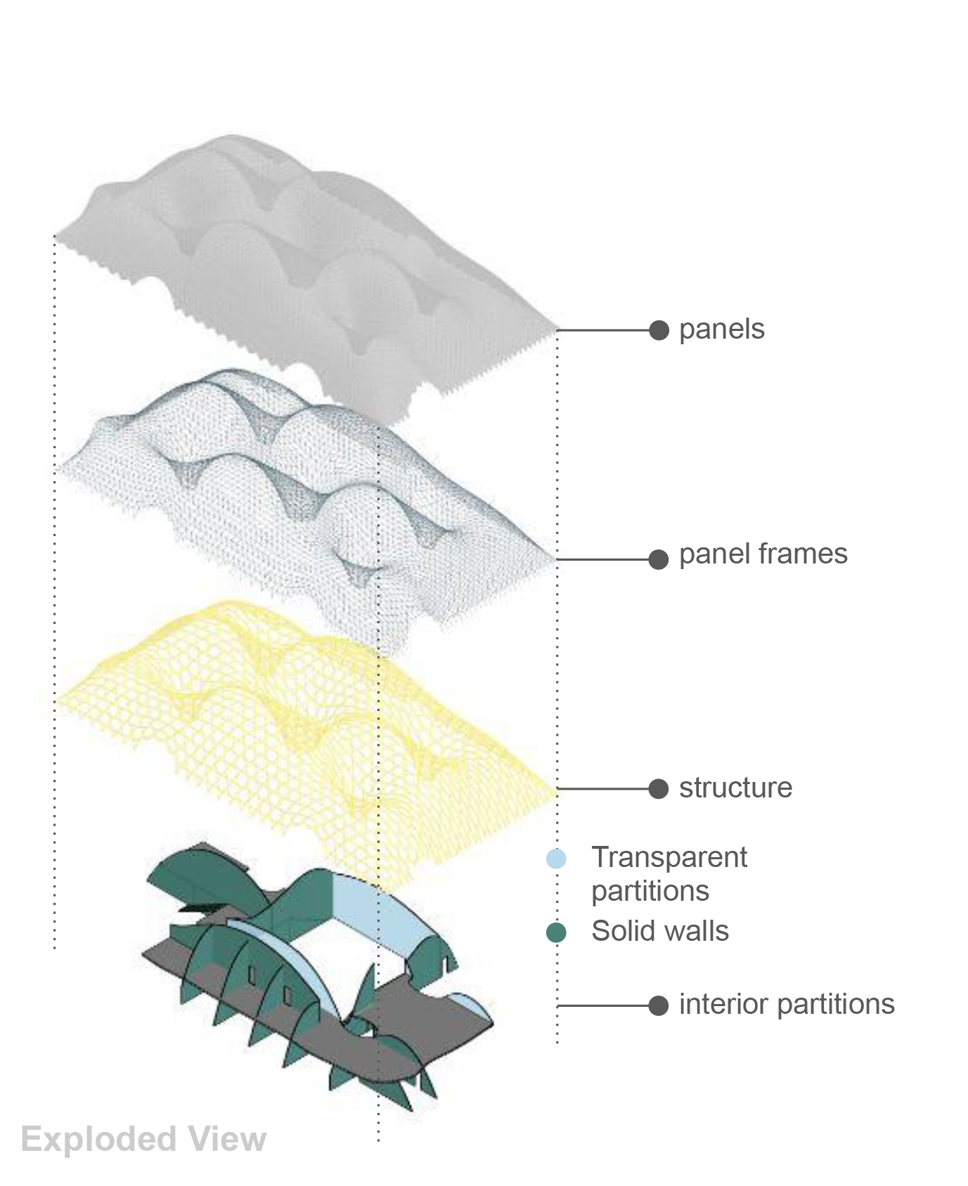
- Installation of façade or roof systems: Due to the ever-changing curvature of the beams, we opted for a system using aluminum profile rails to install planar triangular glass and CLT panels.
Workflow
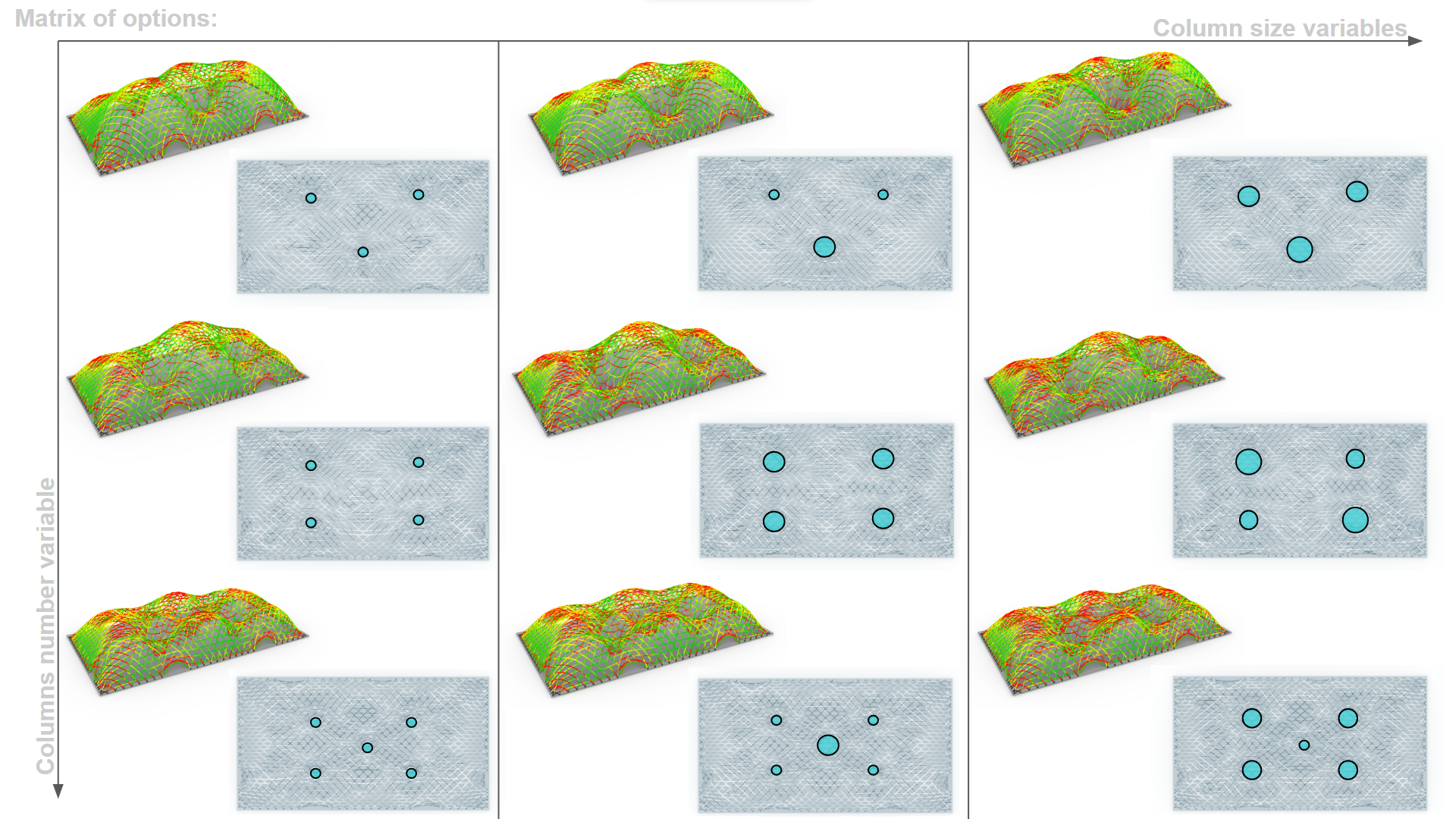
Our design process began with the definition of a rectangular boundary on which the building was to be constructed. Users could also define openings in the gridshell and the positions and sizes of the columns. These inputs helped to determine anchor points in the mesh using Kangaroo software, which then led to the final shape of the mesh. This step also created the Kagome pattern for the subsequent beams.
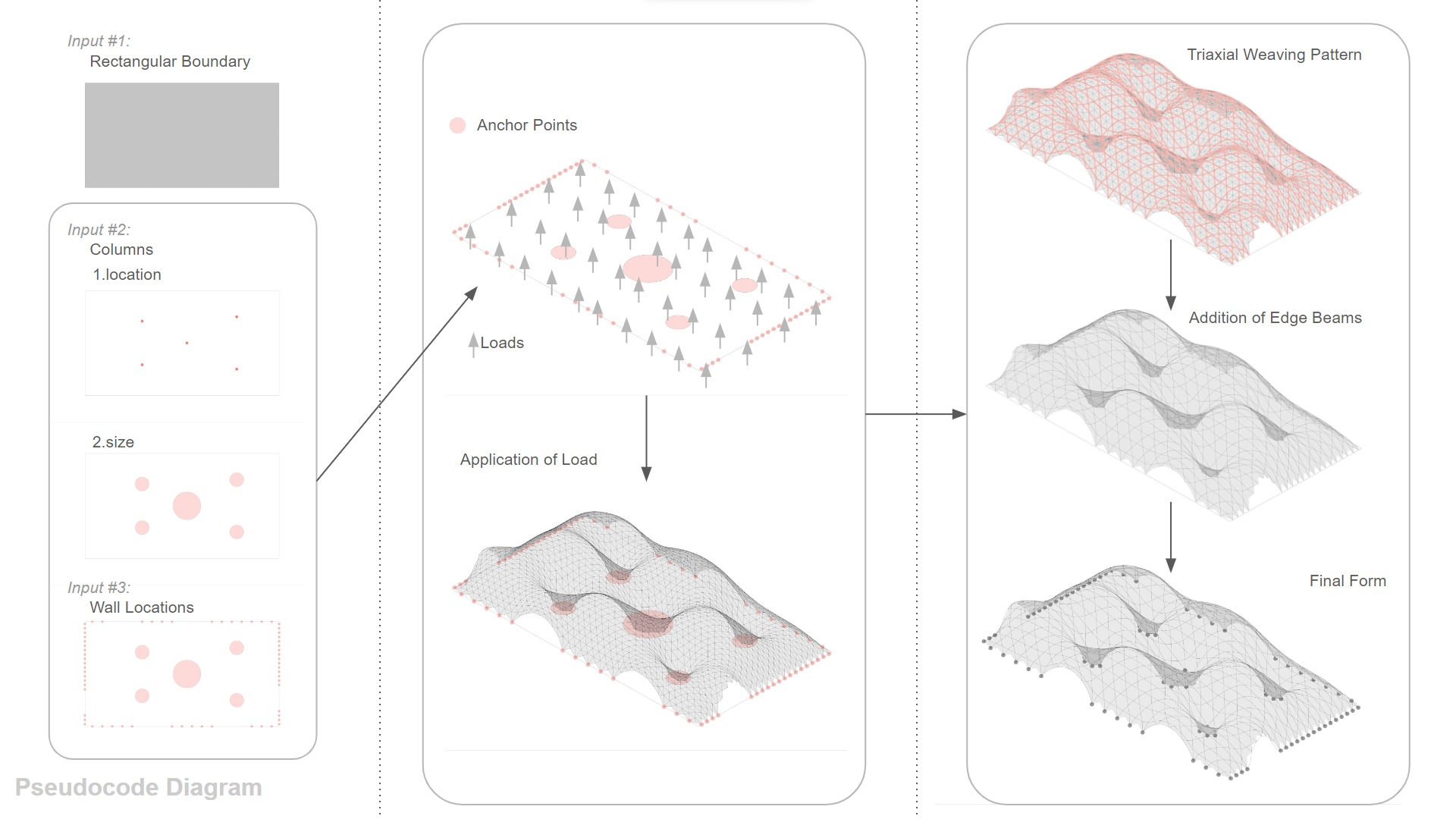
Once we had found the shape, we used the Glulamb plugin to check that the curvature of the generated geometry was within the feasible range. This plugin checks according to Eurocode 5 whether the beam curvature conforms to the standard depending on the slat thickness and displays the results graphically and numerically. This allowed us to quickly iterate on column positions or sizes and check the feasibility of the geometry.
In our “Digital Tools for Structural Optimization Strategies” module, we also analyzed the gridshell as a beam model using the finite element method (FEM) to determine the optimal beam cross-section.
Once the shape and dimensions of the geometry had been determined, we carried out several steps in parallel: We created edge beams at the defined openings, which offer both visual and static advantages by reducing the tendency to buckle. Another step was the development of the roof panel system. As a large part of the building was designed as a library, we placed particular emphasis on the effects of sunlight. Taking into account the highest and lowest position of the sun, we determined the nature of the panels. The aluminum support rails and the glass and CLT panels within them were designed accordingly. In parallel, we materialized the beams from simple lines to a complete solid model with all cut-outs for intersecting beams, which proved to be computationally and time intensive. In addition, sectional planes were created to break down the entire load-bearing system into the aforementioned sub-segments.
Sun light and daylight:
Since there were not any extreme climate conditions from general climate analysis, we directed our focus on sunlight and daylight since we are designing a library, we are dividing our panels into 2 materials one is opaque as glass and the other is solid as Cross laminated timber by calculating the angle between the sun vector hitting the panel and the normal of this panel, upon this we decide which panels will be opaque or solid and also the size of the panel is determined upon remapping the numbers from closest to the normal to the farthest which will allow more daylight in the space while preventing glare at critical times in the day.
The structure is composed of two floors. The first floor is mainly allocated to more public functions like the lobby, cafeteria, library, kids’ area, and meeting rooms, whereas the second floor serves for more specific users as a mezzanine floor with administration spaces, private meeting rooms and computer labs.
CO2-Calculation
With the completion of the above steps, a finished geometry was available, which we used for a CO2 calculation. In order to minimize the CO2 impact, we selected local tree species as raw materials, which were harvested in Adana and transported to Gaziantep, where a manufacturer with the required equipment was identified.
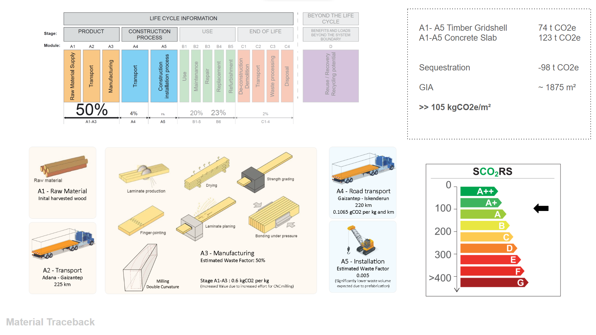
We carried out a CO2 calculation for phases A1-A5 according to the criteria of the SCORS system. Due to the high material consumption for milling double-curved beams, we applied an additional waste factor of 0.5. The CO2 impact for our timber support structure was 74 tons of CO2, sequestration was -98 tons, and the reinforced concrete floor slab generated 123 tons of CO2.
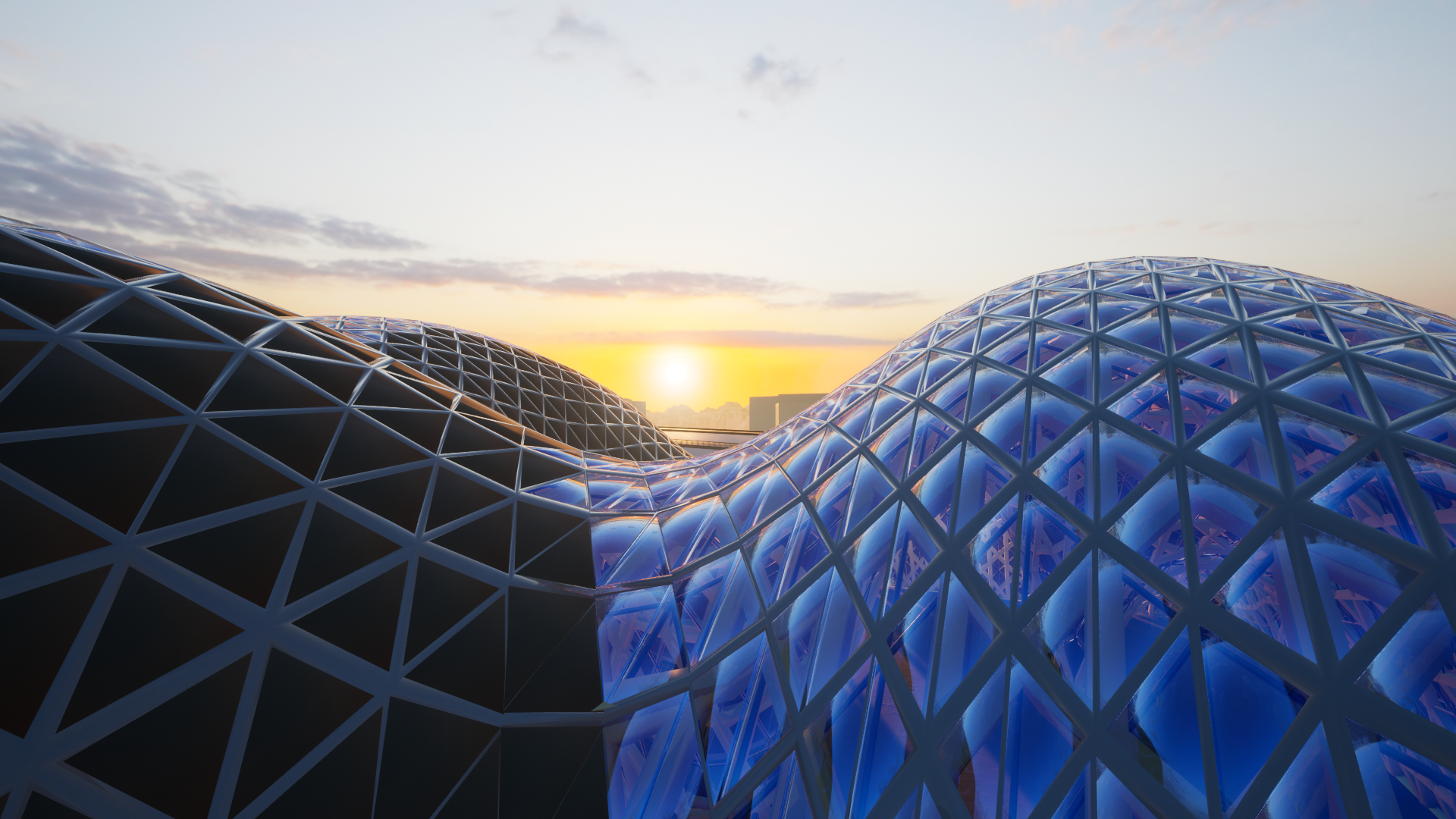
Visualisation
Resources
Illustration Double Curved Glulam
Illustration Glulam Production Steps (edited)
https://parametric-architecture.com/nine-bridges-country-club-by-shigeru-ban-architects
https://arquitecturaviva.com/works/club-de-golf-haesley-nine-bridges-0
https://sjb.ch/project/haesley-nine-bridges-gold-club-yeoju-south-korea/
https://www.seccosistemi.com/en/realizations/haesley-nine-bridges-golf-clubhouse/
