
The drying process is a mass transfer, it removes water or another solvent from a material through evaporation, which is driven by simultaneous heat and mass transfer. Heat is transferred to the material, causing the liquid to evaporate at the surface, and a carrier gas or vacuum removes the vapor from the material’s vicinity. Common drying methods include using hot air (direct drying), applying external heat (indirect drying), vacuum drying, and freeze-drying.
Challenge.
In 3D-printed earthen walls, enclosed cavities trap humidity. Without proper air exchange, moisture cannot escape, prolonging the drying phase, as seen in TOVA, where drying lasted up to four months. During Helia’s fabrication, the team observed a clear contrast between cavities with and without ventilation channels, revealing not only uneven drying, but also an opportunity to optimize the process through controlled airflow.

The Helia wall integrates vertical openings printed along its height to connect internal cavities with the exterior air. These channels create a stack effect, allowing warm air to rise and draw moisture upward and out of the wall.
Objective.
“Optimize ventilation in the cavity system in the wet state (during construction) using geometry to promote airflow, accelerate drying, reduce humidity retention to increase walls drying times.”
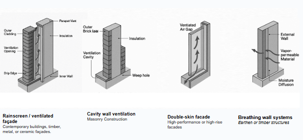
State of the Art.
Scientific Analysis.
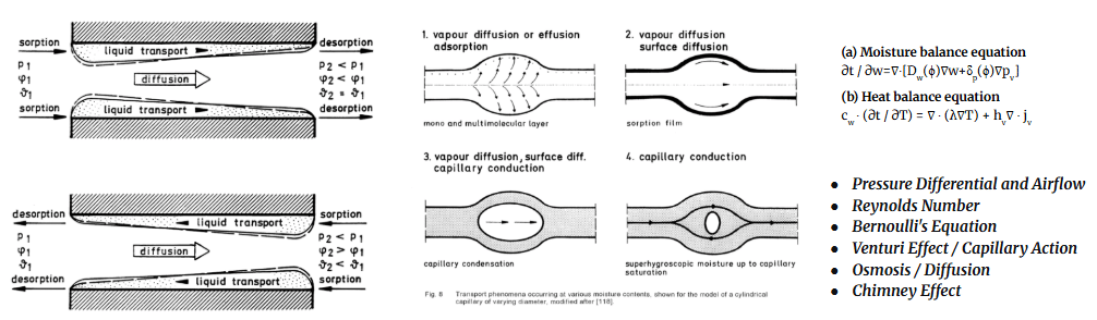
Main Findings
- Moisture transport in porous media is nonlinear—coefficients vary with moisture content.
- Liquid transport dominates at high moisture contents; vapor diffusion dominates at low contents.
- Capillary action and pore-size distribution are decisive in transport efficiency.
Derived coefficients allow improved simulation of realistic moisture transfer in hygrothermal models (such as WUFI, later based on this work).
Experiments.
Part I. Aperture Design.
Our first experiment centered around the geometry of the ventilation. The total surface area of the openings is more significant than their quantity. Both intake and exhaust points must be strategically considered to optimize flow.
Variables Tested
To control all other factors, we standardized scale and shape of the cavity. The following variables were tested by a catalogue of over 18 cylinders. The moisture content was measured over hours, days and weeks for both rate of drying and evenness from base to top.
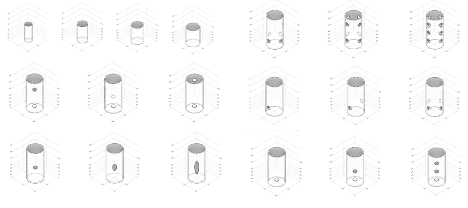
Open vs. Closed Cylinder – Based on osmosis and airflow effects in porous media.
Location of the Penetration –
horizontal. Informed by pressure differentials (Samples A, B + C)
vertical. informed by gravity and temperature of humid air. (Samples 2, 3 )
Number of Holes – Links opening dimension to evaporation efficiency. (Samples 5, 6, 8 + 9)
Thickness of the Walls – Evaluates heat and moisture diffusion through varying
wall mass. (Thinnest Samples 2 +6, Thickest Samples 4, 5 + 12)
Size of the Hole – Links opening dimension to evaporation efficiency and potentially pressure. (Samples 12 + 13)
Size of the Cavity (Volume) – Examines relationship between internal volume and moisture escape. (Samples A, B, C + D)
Shape of the Cavity – Examines how surface curvature impacts evaporation rate. (Samples 10 + 11)

Results were taken for each sample over time and plotted to compare the success of each sample. While results proved inconclusive, common characteristics became evident.
- Weight over time was the best indicator of drying rate.
- An open cavity with holes at the base (or cross ventilation) improves drying.
- The mass of the wall has more influence on drying rate than the cavity size has little correlation to drying speed.
- The cylinders with 8 and 12 holes dried faster than all other cylinders. The size and quantities of the penetrations seem to have a quadratic relationship to the drying rate, where too much surface area or too little negatively impacts the rate of drying.
Cylinders printed later in the day seem to dry less consistently than those printed earlier in the day. This may be due to change in relative humidity / barometric pressure of the lab through the course of the day..
Simulation Matrix.
THERM simulation software was employed to examine the direction force (pressure) is impacted by apertures.
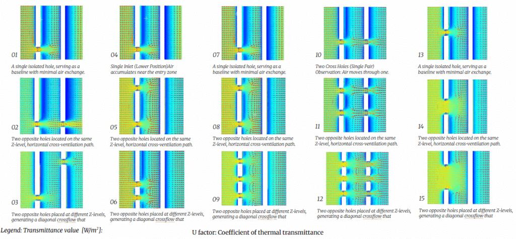
Part II: Cavities.
From this initial analysis aperture design, the investigation continuted employ the information gleaned to examine how air may flow from through wall cavities (modeled by IAAC’s Tova geometry).
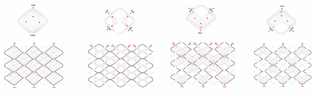
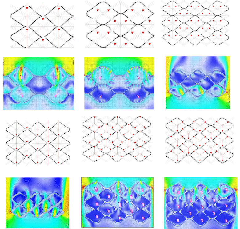
Each configuration was simulated and results were documented:
Best for drying efficiency: Cross-Hole (Aligned Inlet–Outlet)
Best for balanced internal coverage: Diagonal Flow
Best for mixing but not reach: Central Converging Flow
Weakest airflow and drying performance: Side-Hole Configuration

Conclusion.
These observations were once again tested with a physical model, printed at 1:3 scale with clay. Initial warm vapor will rises so placing a vent higher is effective for exhausting moist air (like bathroom exhaust fans found on the ceiling.) As residual vapor cools, Chimney Effect will employed by penetrations at varied heights and sizes, allows air to move through the cavity via pressure differentials expediting the drying.
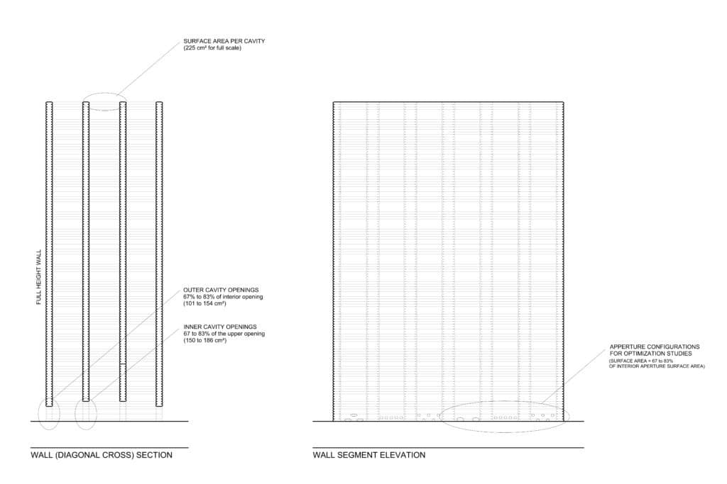
For this experiment, drying process suggests moisture content moving from inside cavities out over time successfully. After one week, moisture inside cavities reduced by 6.5 and 7% while exterior moisture maintained relative constant moisture. While it was not tested, the Stack Effect suggests that the surface area of the holes at the base should be equal to 67% to 83% the size of the surface area of the cavity at the opening (top of the shaft) to optimize the pressure exchange. Future tests may be conducted to decrease the aperture from interior cavities to exterior cavities to draw moisture from the wettest cavities out.
A 1:1 scale model was created to automate a ventilation system. Two prototypes were created, testing printing speeds, pressures, and nozzle dimensions.

In the coming months, collaboration with texture and structure research will allow us to employ variation of the aperture size (even smaller openings) via manipulation of the toolpath and test the pressure exchange shown in the 1:1 scale mock up in the construction environment.
