Project Overview
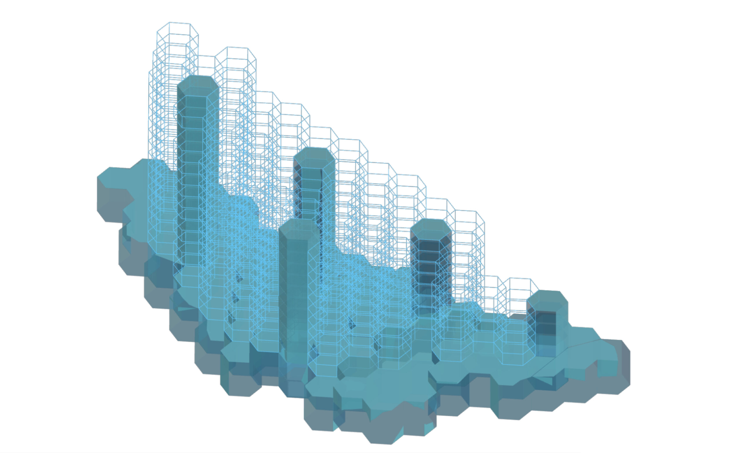
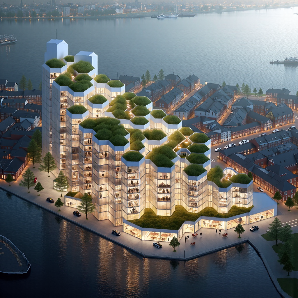
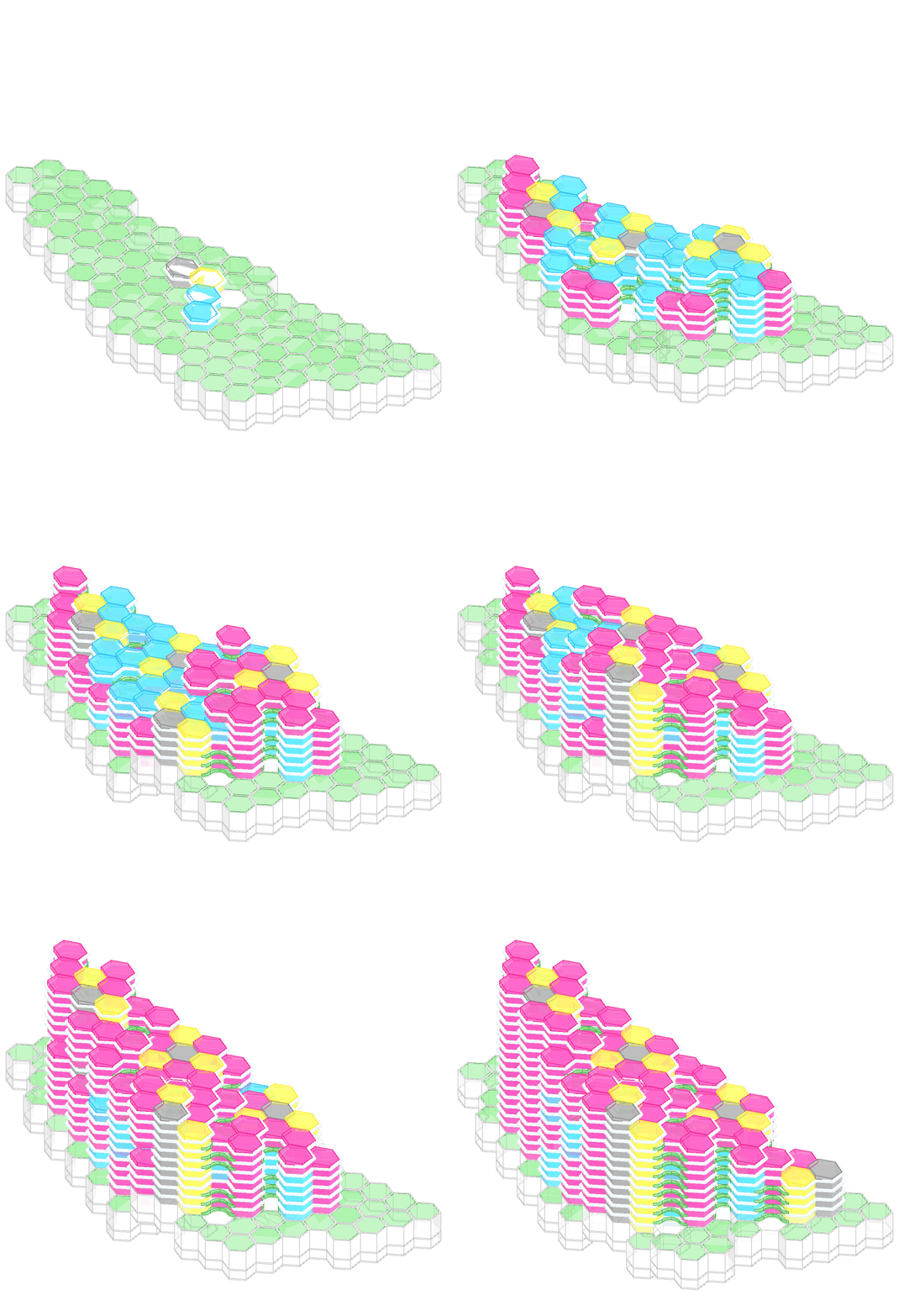
This structural analysis and optimization focuses on a studio project designed as an office and industrial hybrid typology housing creative industries, such as architecture studios and robotics fabrication labs. The building is generated through an aggregation process, resulting in variable building heights that generally fall within high-rise parameters.
The structural system consists of a hybrid design featuring a concrete podium foundation with vertical support cores. These cores provide resistance to lateral movement caused by wind and seismic forces and connect to a steel structural frame supporting the modular units. The secondary structure, made from steel round hollow sections, forms a lightweight yet robust framework, ensuring scalability and adaptability to changing module requirements. This structural system resembles a “multipipe” design with interconnected tubular elements for efficiency and dynamic visual appeal.
Strategy // Concept
Concrete Podium
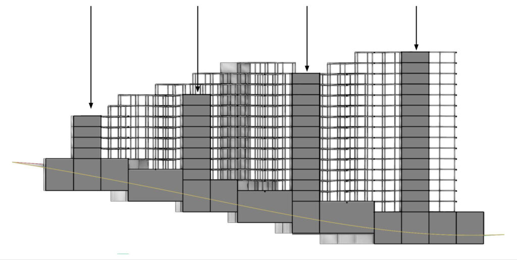
Concrete core and podium as the foundation. The concrete cores provide vertical support, prevent lateral movement by resisting wind and seismic forces, and act as the central structural elements around which the modular units will be built. The podium distributes horizontal loads and supports the modular units above, creating a strong and stable base for the hybrid system.
Steel structures
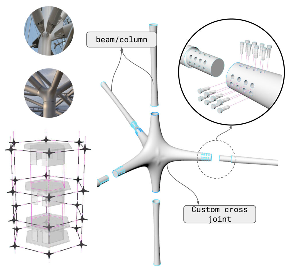
The structure consists of a modular steel beam system using round hollow sections (O-sections) to form a lightweight yet strong framework. The modular design allows for scalability, enabling the structure to grow and adapt to changing needs over time. Architecturally, the system resembles a multipipe configuration, with interconnected tubular elements creating a visually dynamic and structurally efficient form. This approach ensures flexibility, ease of assembly, and efficient load distribution across the system.
Strategy // FE model
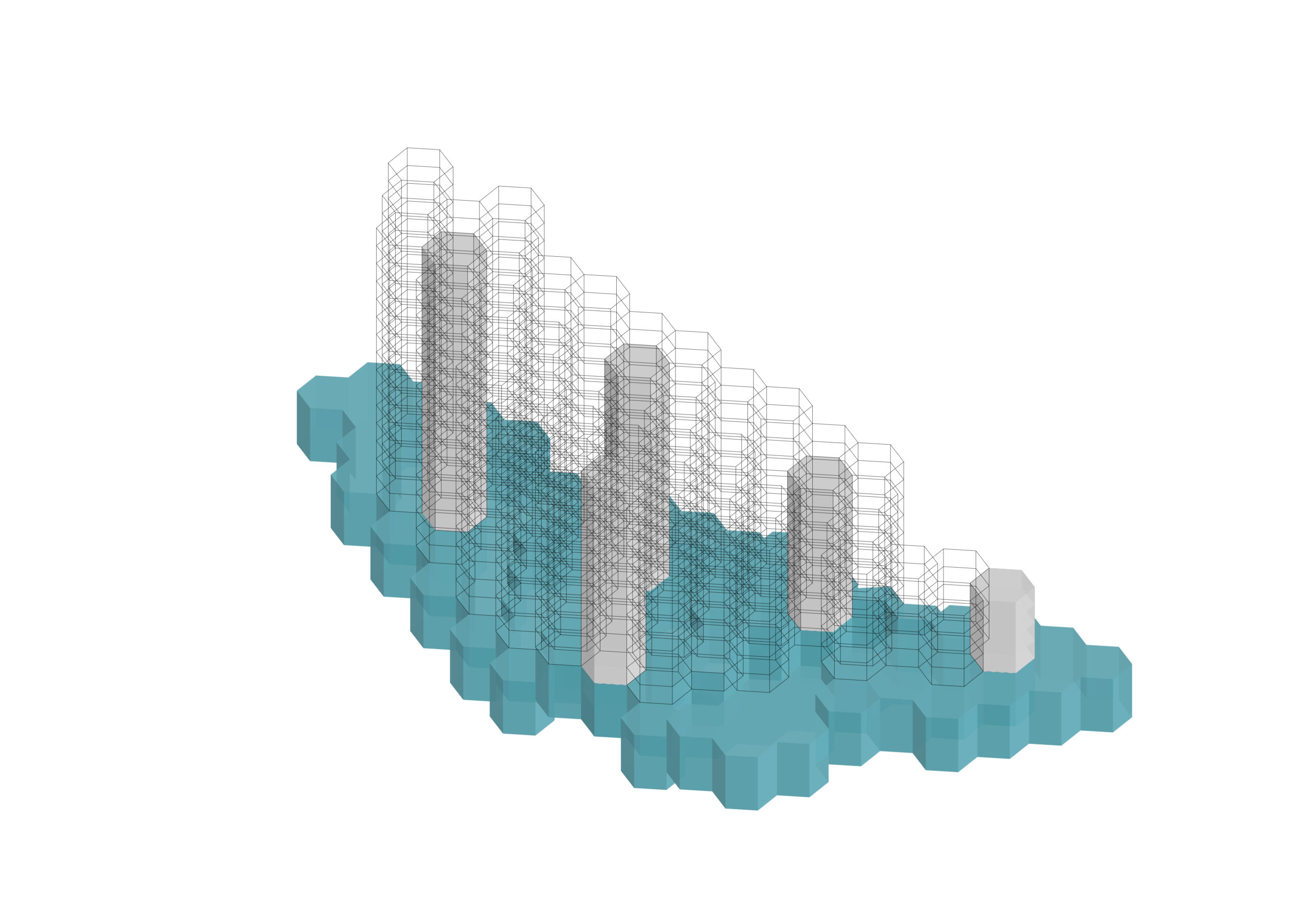
Concrete Podium
The podium was modeled using its surface geometry, with the faces assigned as concrete shell elements to represent material properties accurately. This approach ensured an efficient analysis of load distribution and structural behaviour.
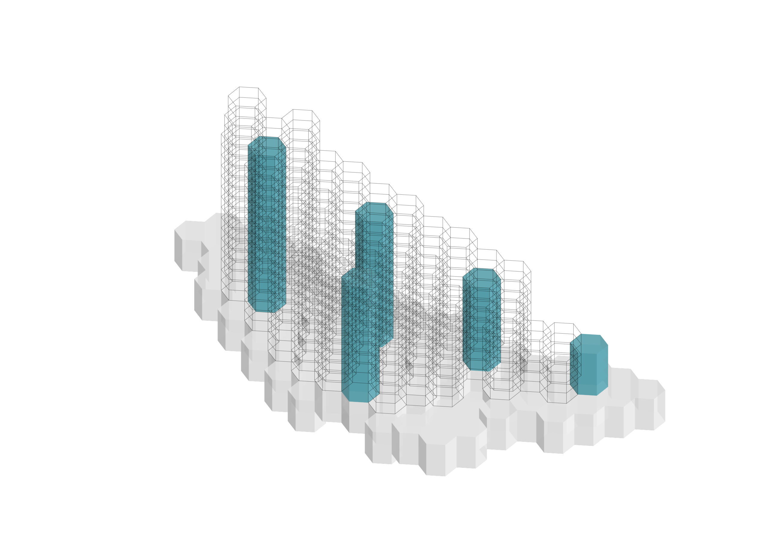
Concrete Core
The cores were modeled as concrete shell elements using their surface geometry to transfer vertical loads, resist lateral forces, and ensure structural stability.
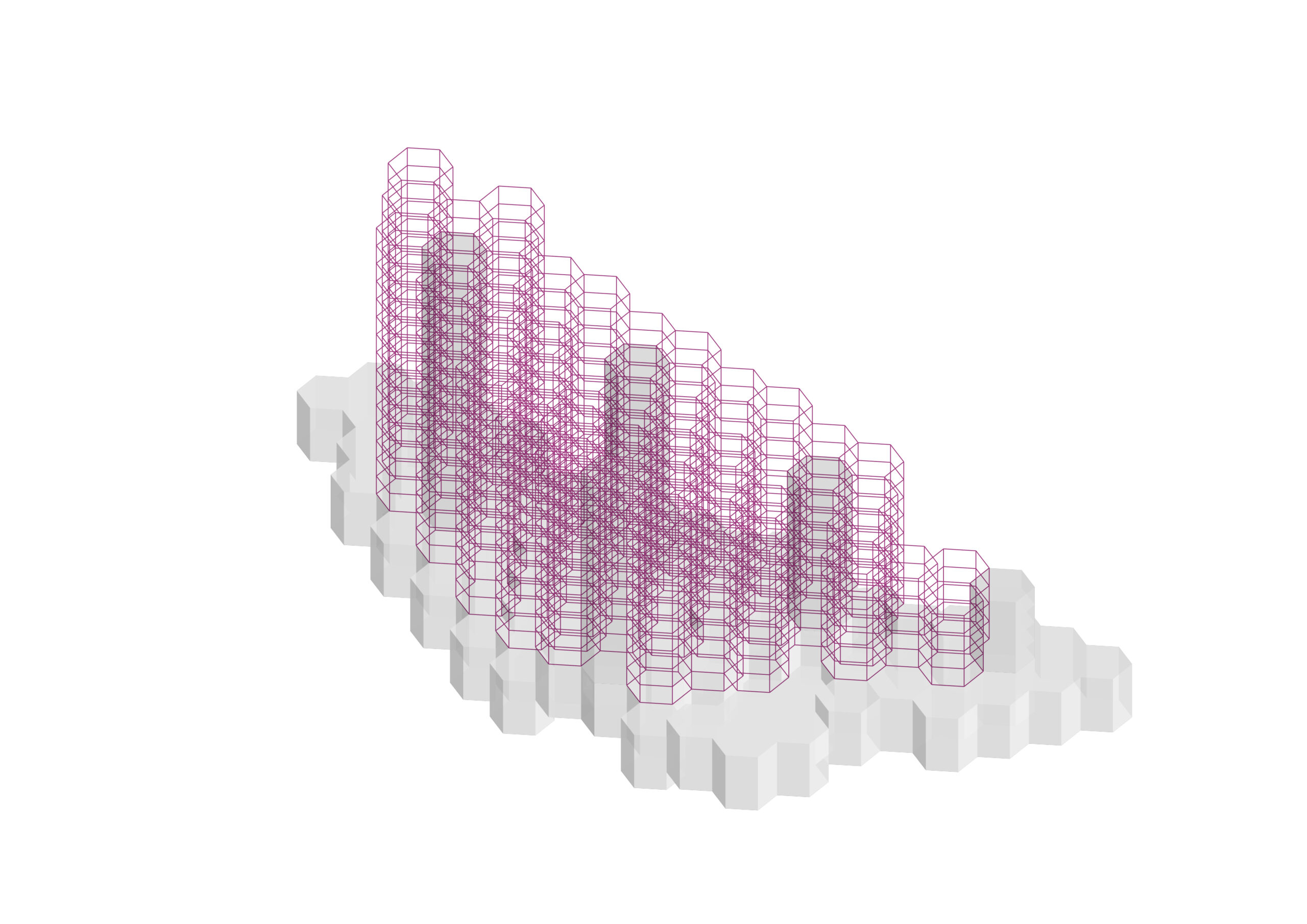
Steel O-Section Beams
The beams were modeled using the edges of the hexagons and assigned as steel elements with a 0 cross-section, accurately representing their structural role and material properties
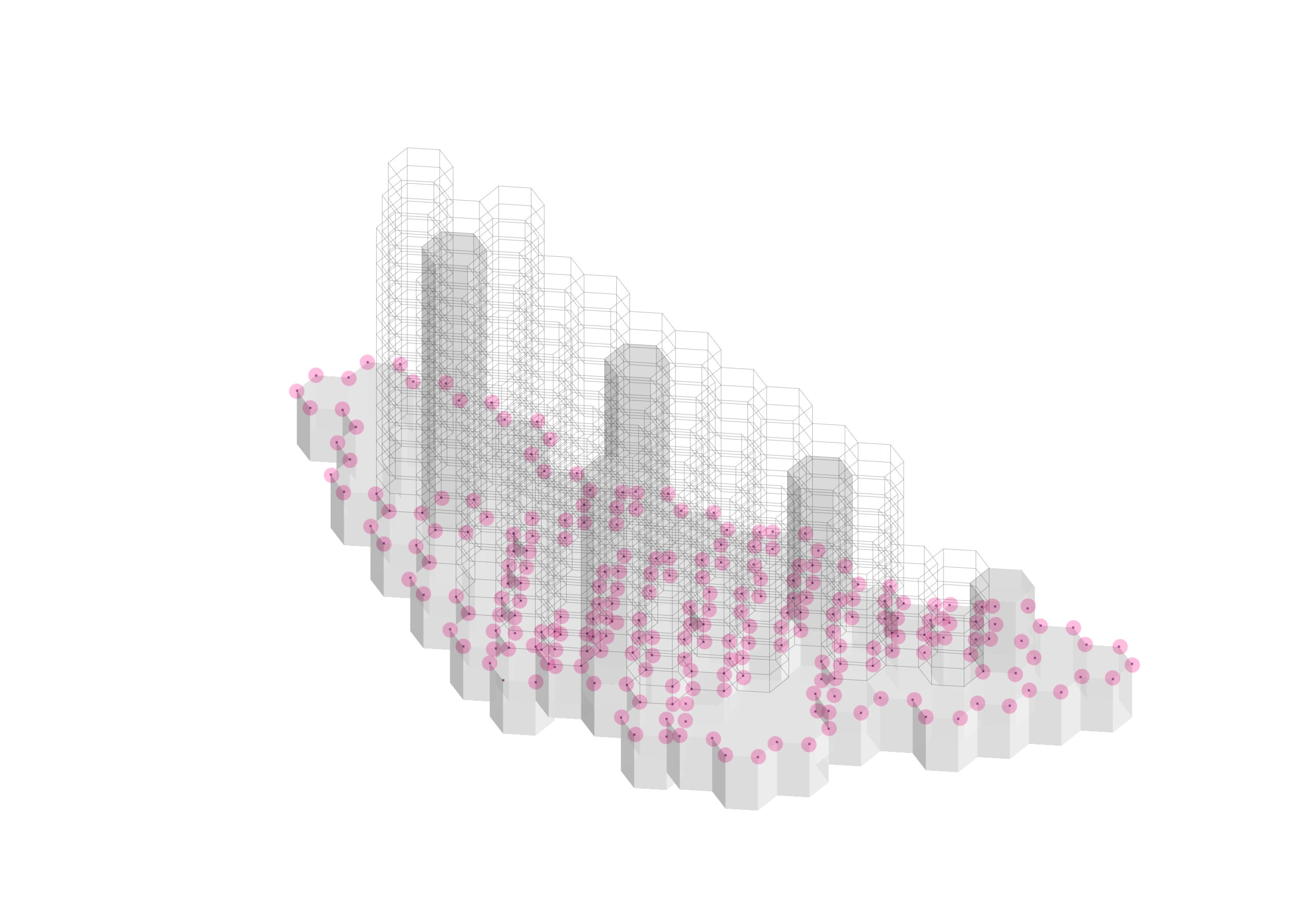
Supports
The supports were modeled using the points of the hexagons that connect to the podium, ensuring accurate representation of load transfer to the foundation.
Concrete Slabs
The slabs were modeled using the bottom surface of the hexagons, with concrete material assigned to represent their load-bearing and distribution properties effectively.
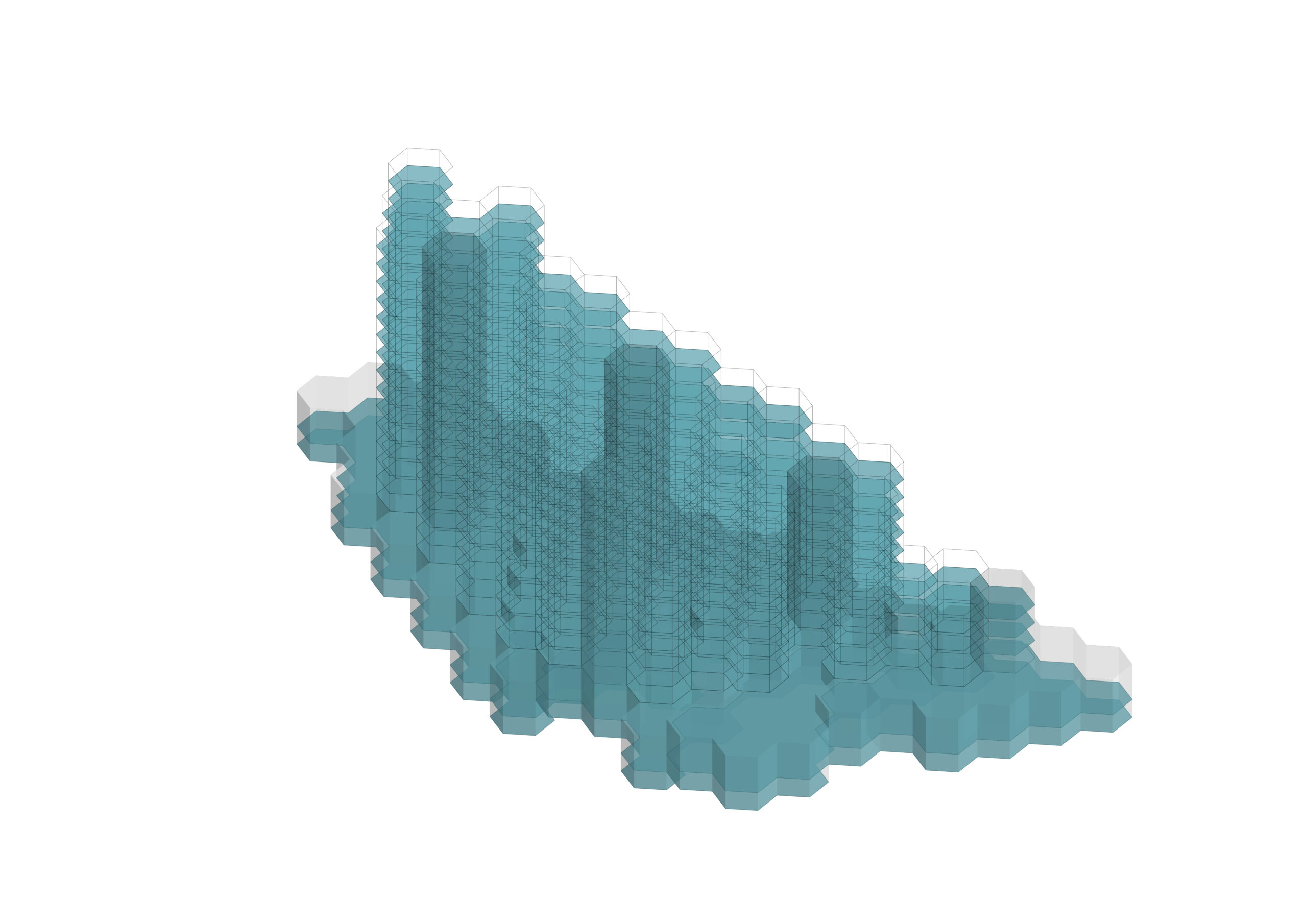
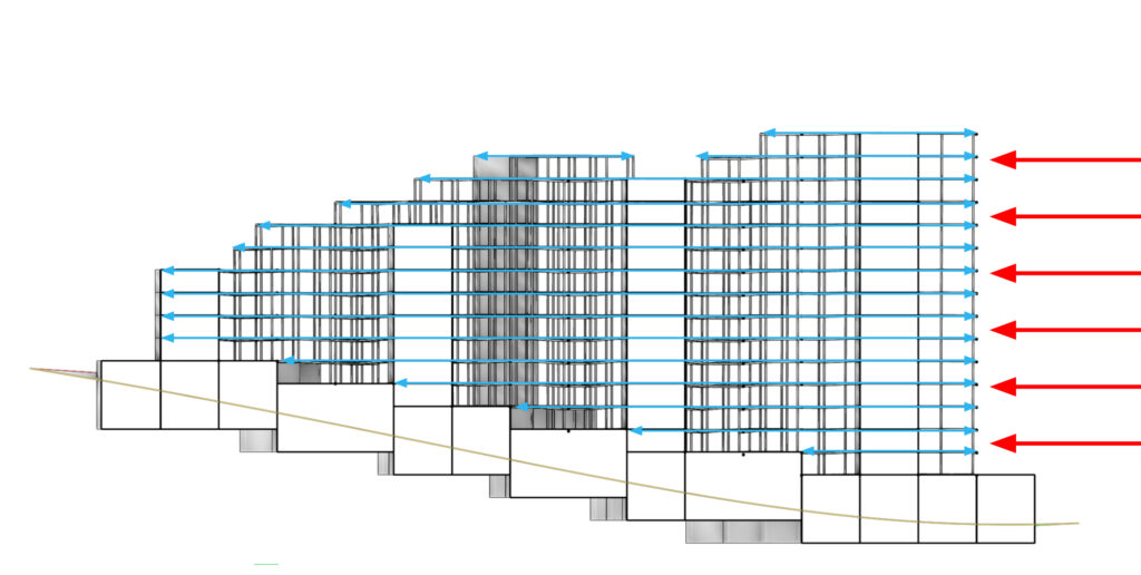
Wind Load
The north-facing facade was modeled using the surface of the hexagons oriented toward the north, assigned to simulate wind loads accurately.
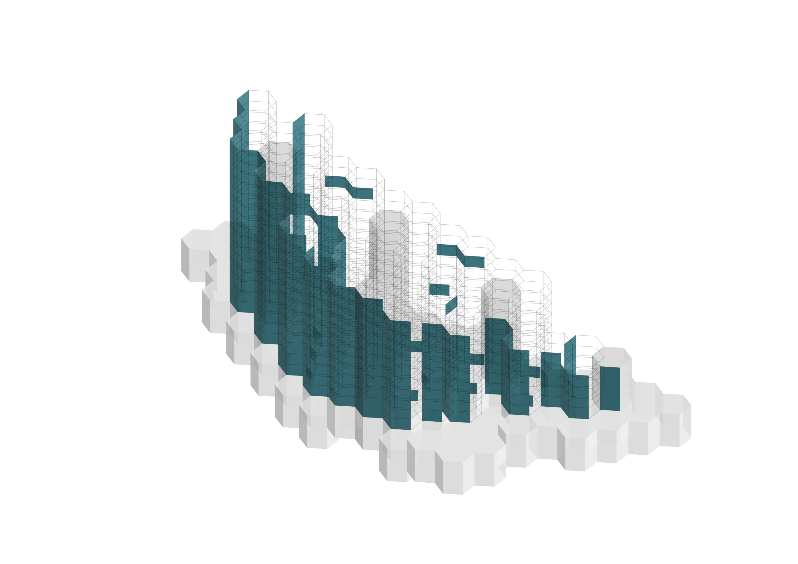
Structure // Key elements
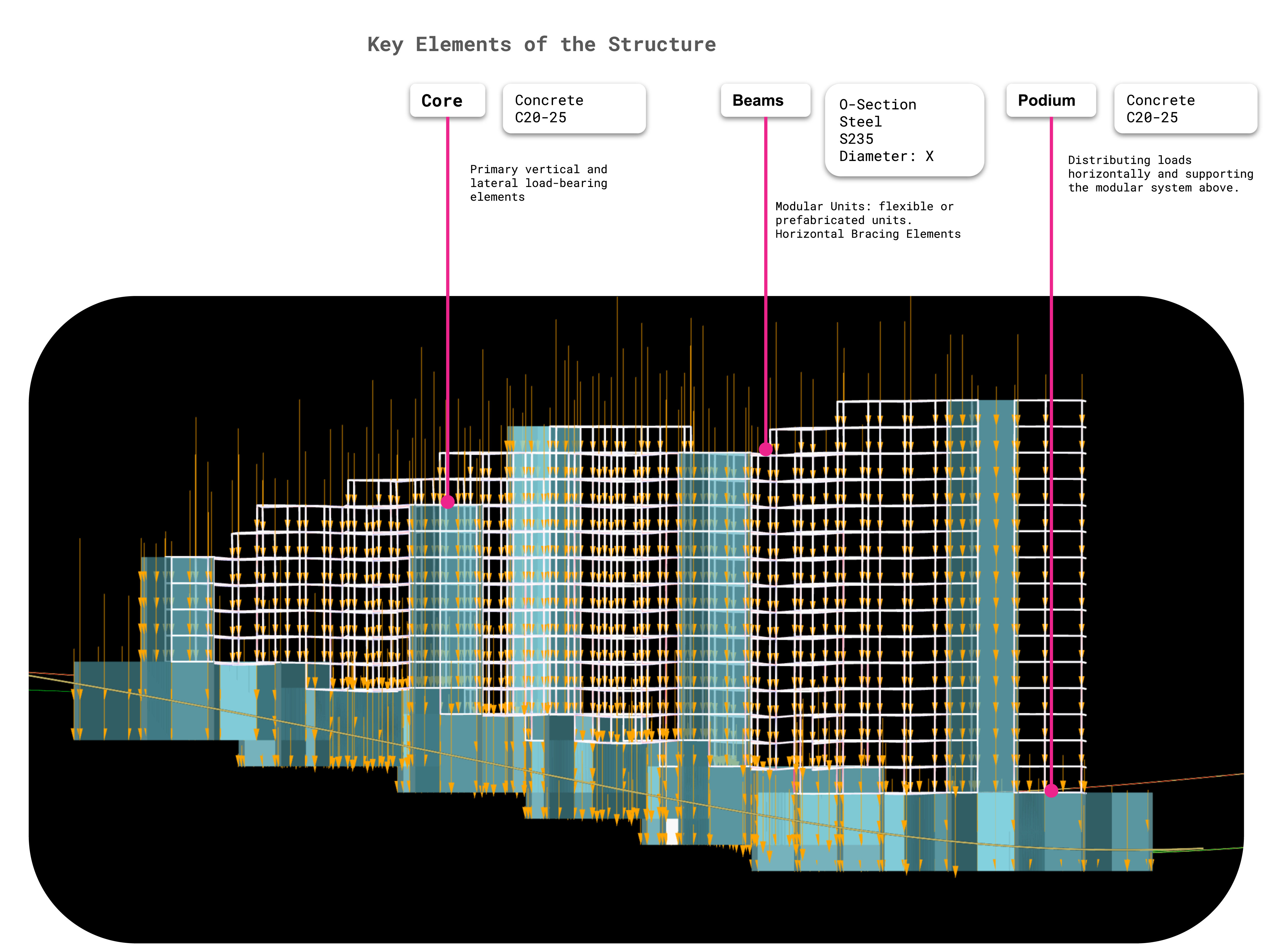
Structural Specifications
The building elements were specified for optimal performance:
- Cores and Podium: Designed as C20/25 concrete, ensuring strength for vertical and lateral load bearing.
- Steel Beams: Prefabricated S235 steel beams act as horizontal bracing, with variable diameters and thicknesses optimized for efficiency.
- Concrete Slabs: Provide horizontal load distribution and support for the modular steel system.
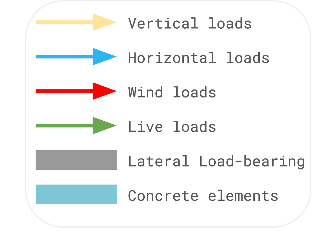
Live Load
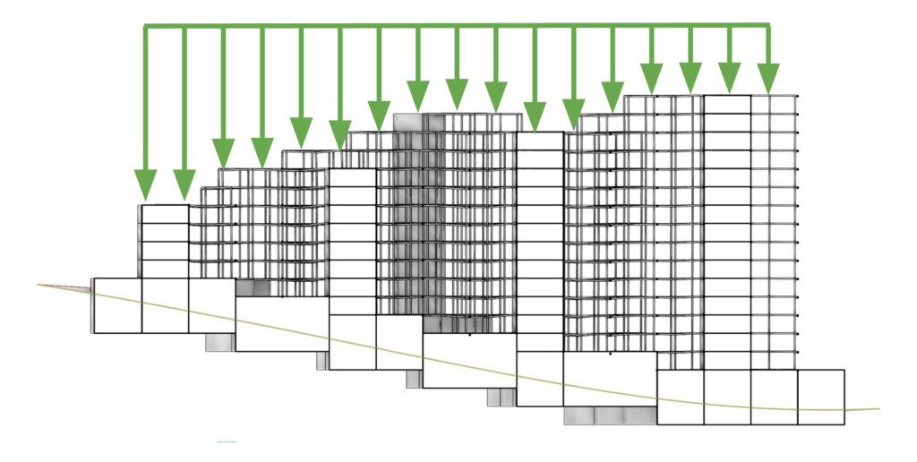
Horizontal Load + Wind Load
Lateral load-bearing element
Structure // Design exploration + Optimization
The secondary steel structure underwent a cross-sectional optimization to:
- Minimize maximum displacement.
- Maximize material utilization within acceptable parameters.
- Reduce material waste by ensuring uniform beam utilization.
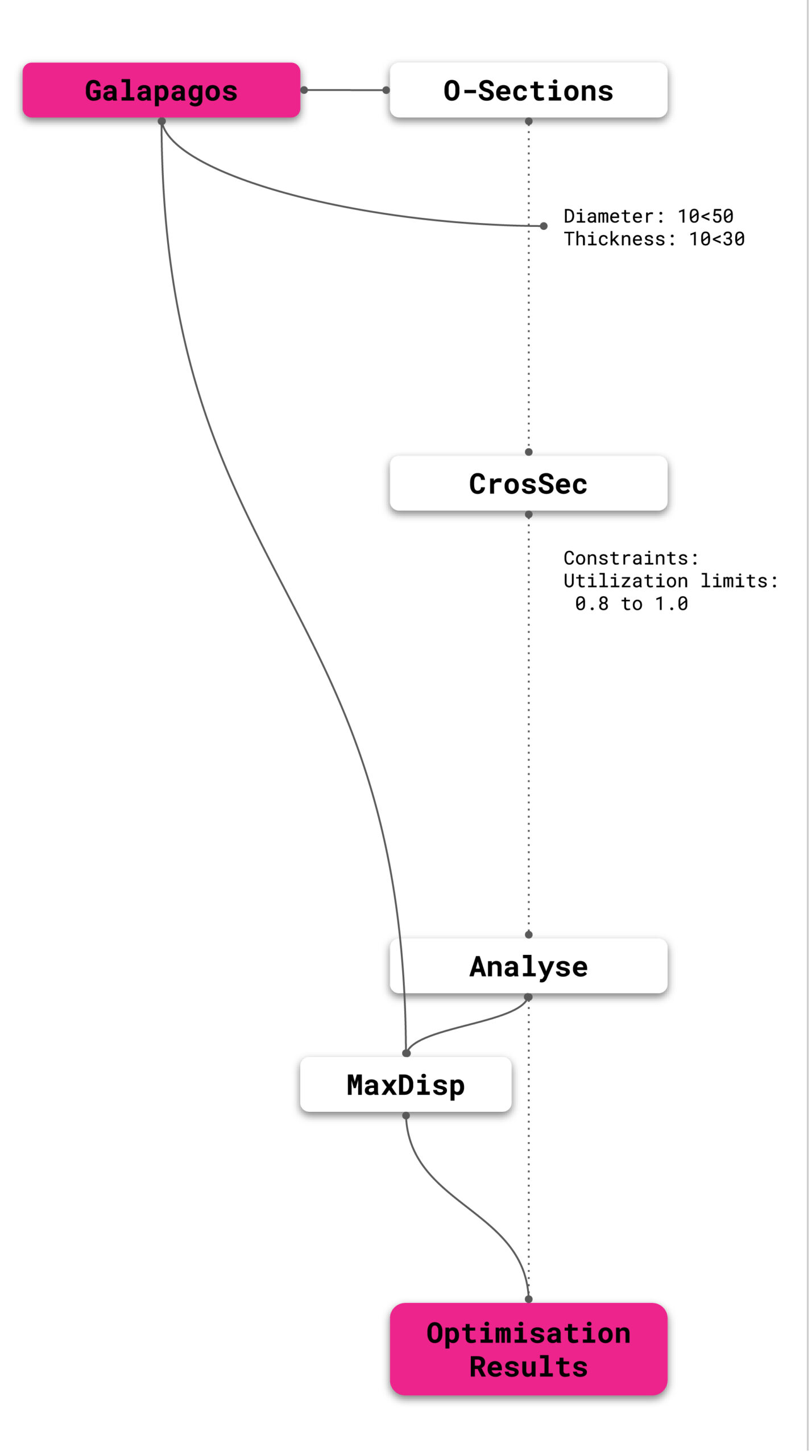
The process involved setting variable diameters (10-50cm) and thicknesses (10-30cm) for steel cross-sections, applying hard constraints for utilization, and analyzing buckling moments to address horizontal loads. Additional interior concrete walls were introduced to provide further support and address deformation caused by aggregation.
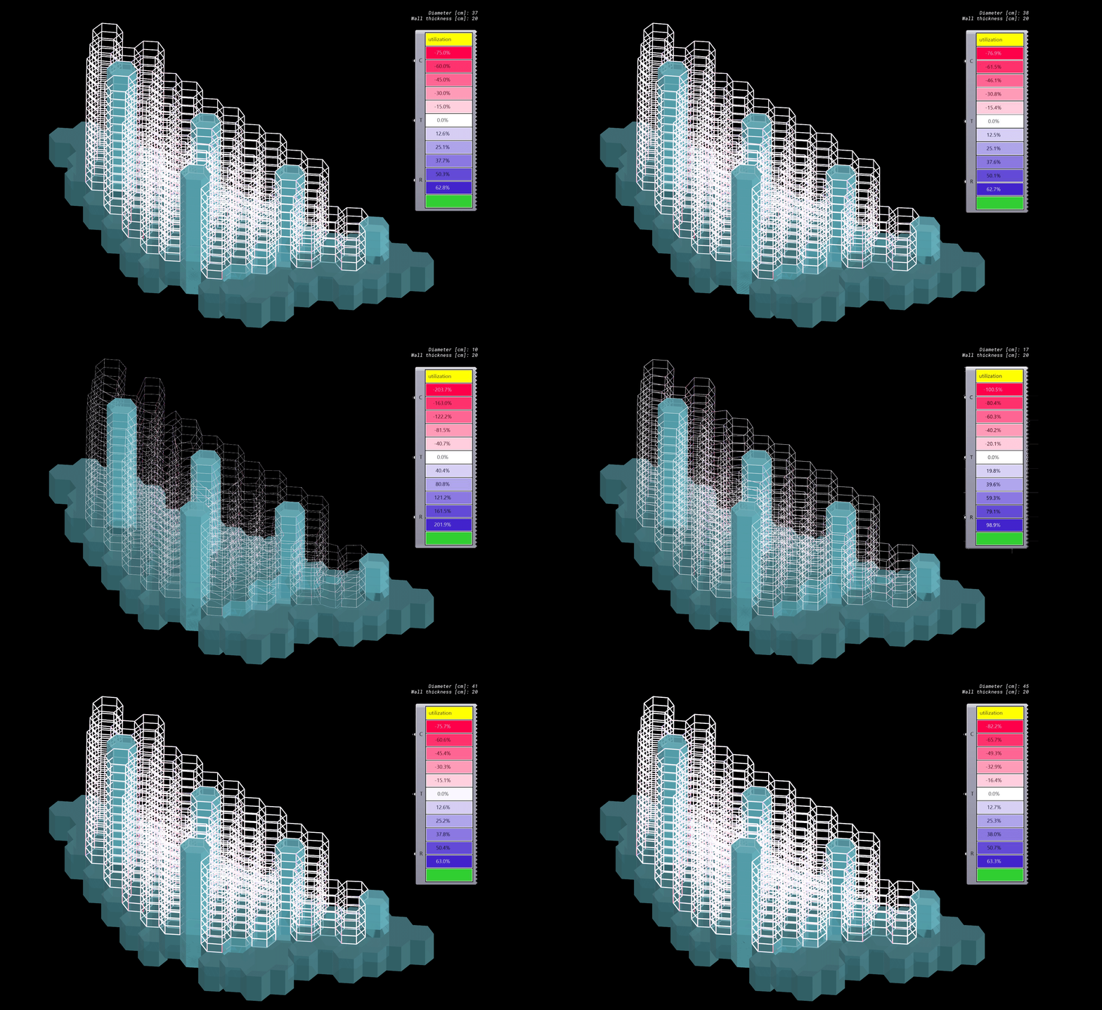
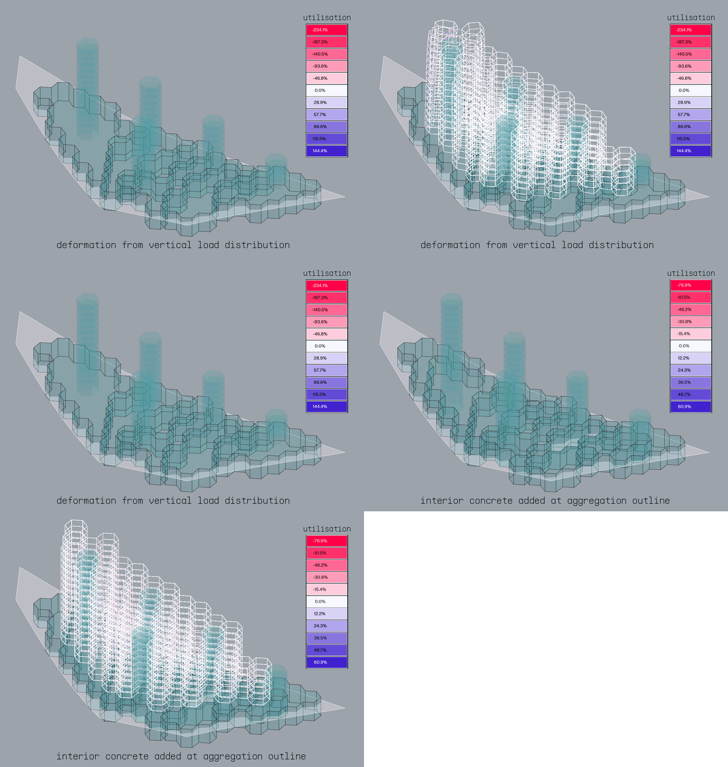
To fix deformation resulting from the lack of supports when the load transfers from the aggregation to the podium, we added additional interior concrete walls within the podium that follow the aggregation outline. This one design move changed the max utilisation of each beam significantly, and resulted in a much more stable structure.
Structure // Analysis Results
Inputs
Materials:
Slabs:C20/25
Core: C20/25
Beams: Steel O-Section – S235
Diameter: 40cm
Wall thickness: 20cm
Loads:
Gravity
Wind: y -0.200
Floor: z -0.5
Supports:
On podium roof slab Tx Ty Tz (beams)
Core: C20/25
Interior Podium Walls: C20/25
Results
Total Material used:
Steel: 62,344,000kg
Concrete: 189,467.85kg
Total CO₂ Footprint (Steel + Concrete):
115,335,400+28,420.18=115,363,820kg CO₂
C02 Footprint:
Steel
CO₂ Footprint=62,344,000kg×1.85kg CO₂/kg
CO₂ Footprint=115,335,400kg CO₂
Concrete
CO₂ Footprint=189,467.85kg×0.15kg CO₂/kg
CO₂ Footprint=28,420.18kg CO₂
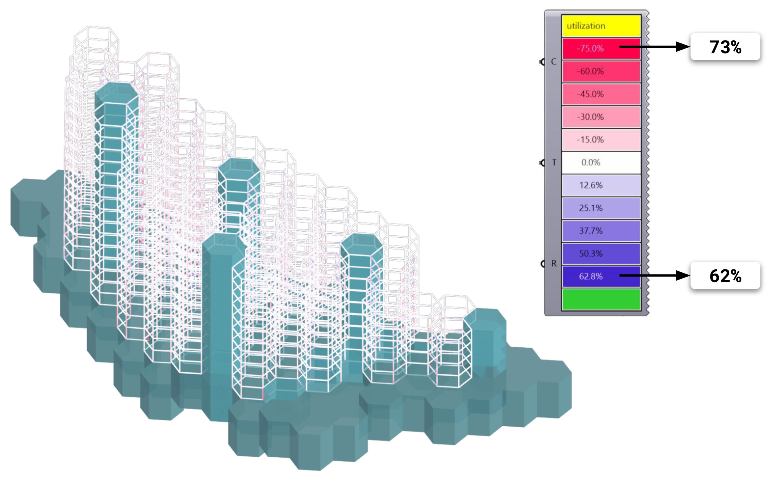
Stress
Displacement
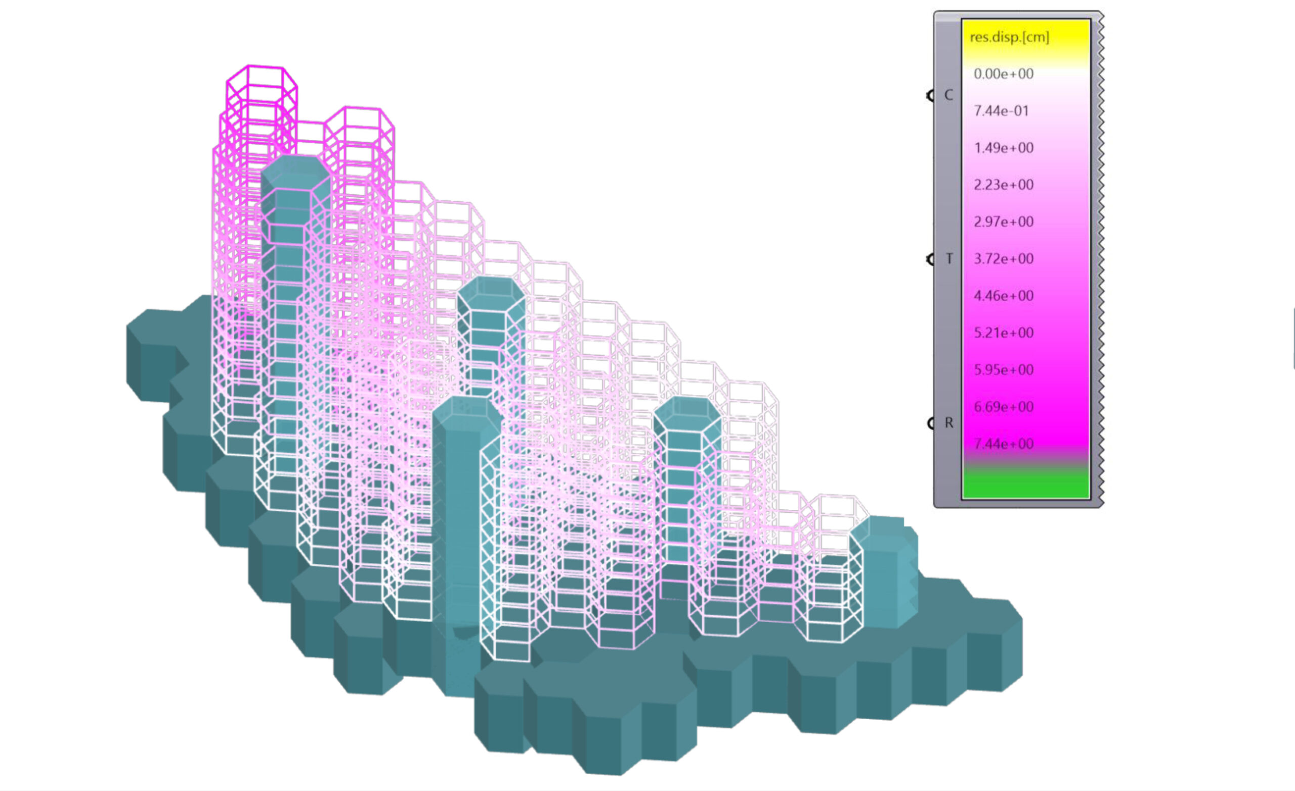
Deformation
