
github: https://github.com/intellection-mrac/tres_mosqueteros.git
1. Intro
When we think of craftsmanship, we imagine a world of deep expertise—one that is developed differently from the academic theories taught in universities. Craftspeople spend years under the guidance of masters, becoming part of a lineage that passes down specialized knowledge honed through time and experience. This process is more than just skill-building; it is the embodiment of tradition, intuition, and muscle memory cultivated through thousands of hours of practice.
In recent months, we have been exploring the integration of pneumatic chiseling with 6-axis robotics. A key area of our research focuses on embedding traditional craftsmanship into robotic processing. Specifically, we aim to understand how the knowledge of skilled stonemasons—who typically require 3 to 6 years to progress from apprentice to master—can be captured, analyzed, and incorporated into advanced construction workflows. This involves investigating how centuries-old muscle memory and intelligence can inform robotic tool paths, leading to a more nuanced and responsive approach to stone carving in the digital age.
2. Aim
This project aims to capture and analyze data from manual chiseling, enabling us to apply traditional craftsmanship insights to robotic fabrication. By recording both motion and force data, we gain a deeper understanding of the techniques used by skilled artisans. These insights can then be translated into robotic tool paths, bridging the gap between human intuition and automated precision.
3. Data Collection
Our data capture setup consists of two interconnected systems: computer vision using an RGB camera and a mountable gyroscope-accelerometer sensor. These systems work in tandem to precisely map the complex motion of chiseling stone, capturing both external movement and internal force dynamics.
4. List of Materials
- ESP32
- MPU6050 Sensor
- RGB LED
- KCD4 Rocker Switch
- TP4056 Charging Module (Type-C)
- 3D-Printed Casing
- Webcam
- 3.7V Lithium Battery (2000mAh)
- TP4056 Charging Module (Type-C)
5. System Integration
5.1 Computer Vision Setup
- Camera Setup
- The webcam is positioned parallel to the working surface to minimize distortion and ensure accurate tracking.
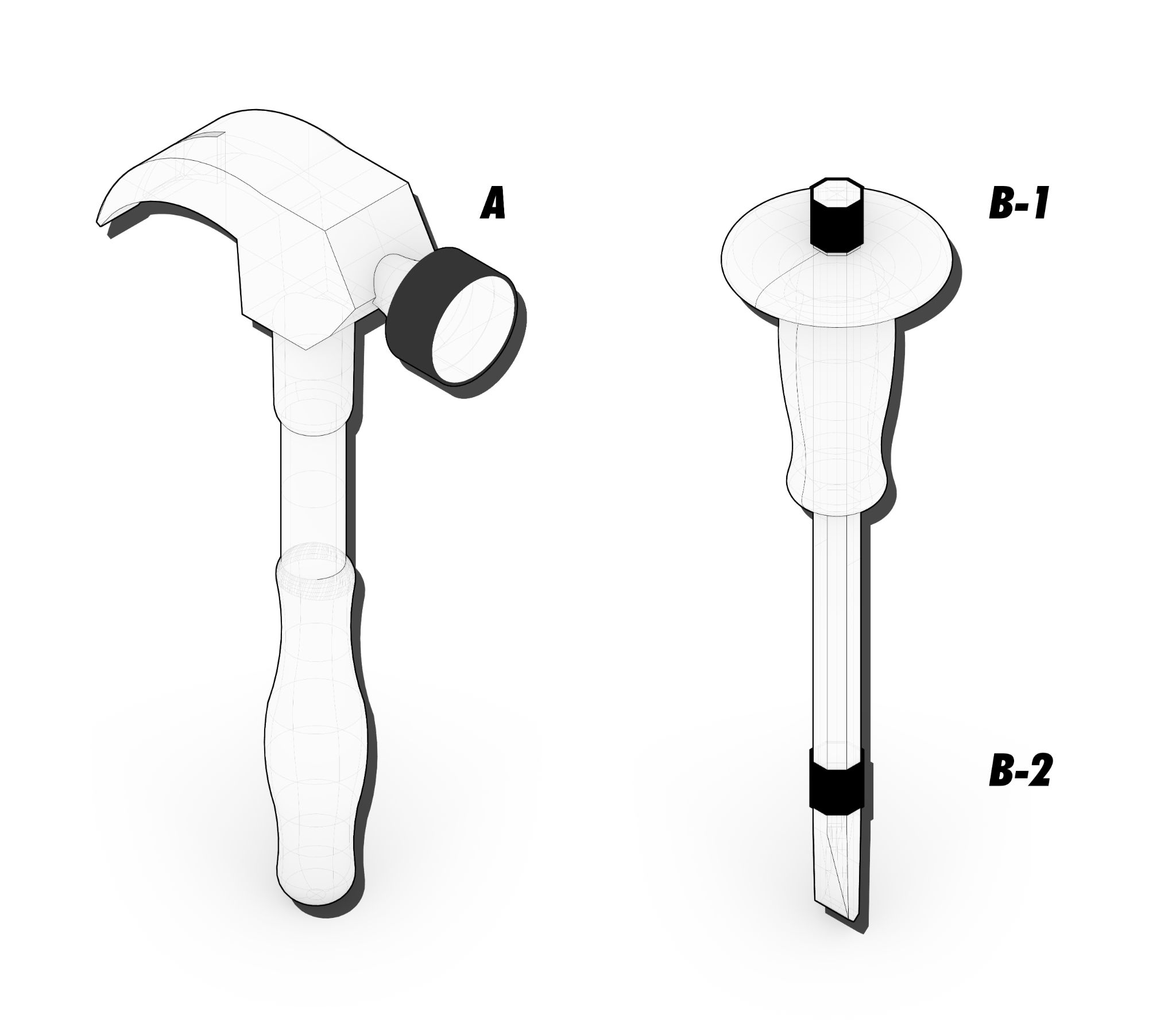
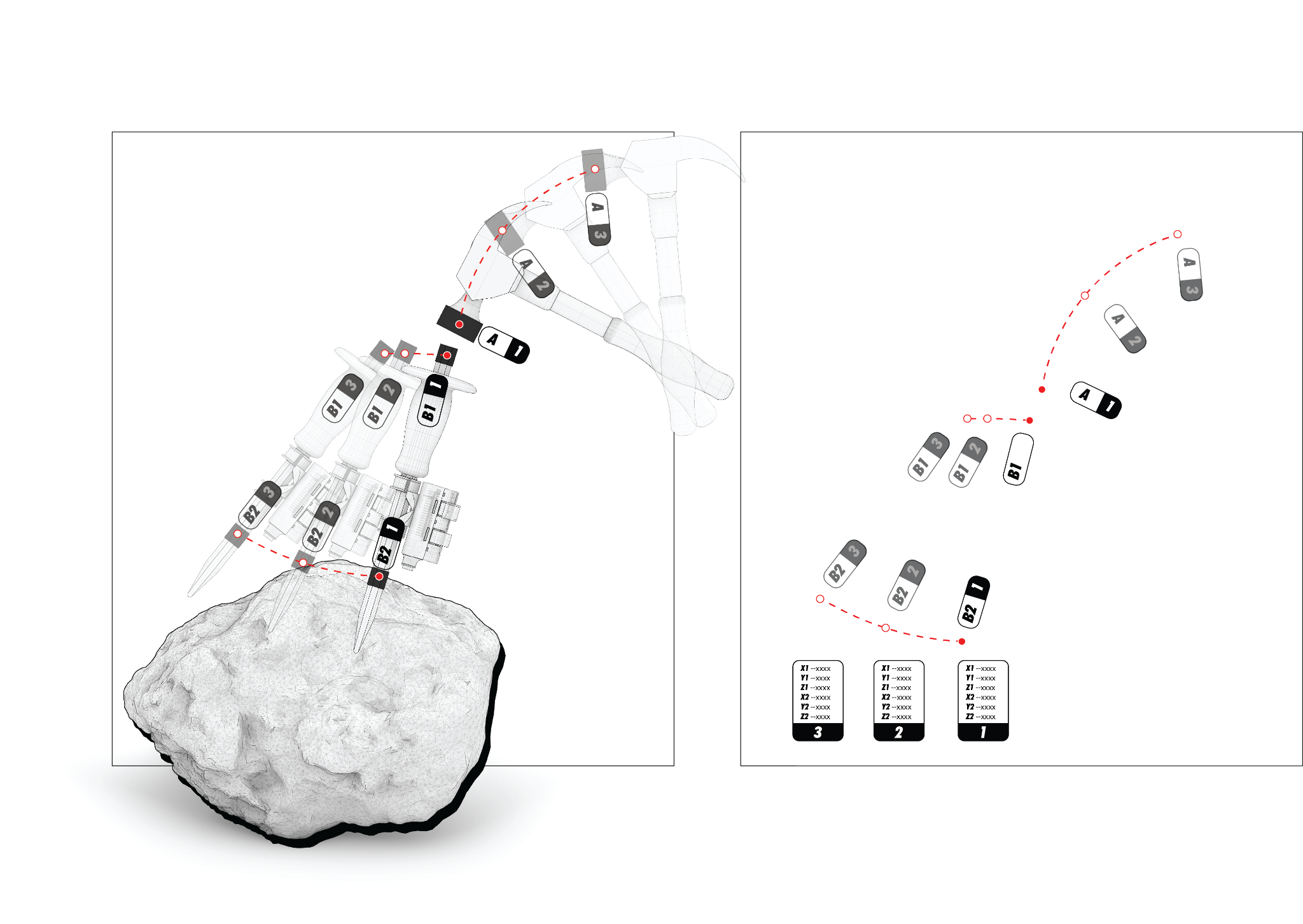
- Marker Placement
- One marker on the hammer head tracks its velocity.
- Two markers on the chisel (one near the tip and another further up) track its movement direction.
- Marker Selection
- High-contrast colors are used to ensure reliable detection under controlled lighting conditions.
- Data Recording
- OpenCV tracks the (x, y) pixel positions of the markers in real-time, frame by frame.
- Data is timestamped and exported to CSV for further analysis.
5.2 Motion Sensing Device Setup
- Sensor Selection
- We used an MPU6050 sensor, which provides 3-axis gyroscopic and 3-axis accelerometric data.
- Microprocessor
- An ESP32 microcontroller is used to capture, process, and wirelessly transmit sensor data.
- Data Processing
- Python is used to capture, post-process, and record sensor data in real time.
Both systems were synchronized and recorded into a CSV file using Python, creating a
timestamped dataset of all captured motion data.
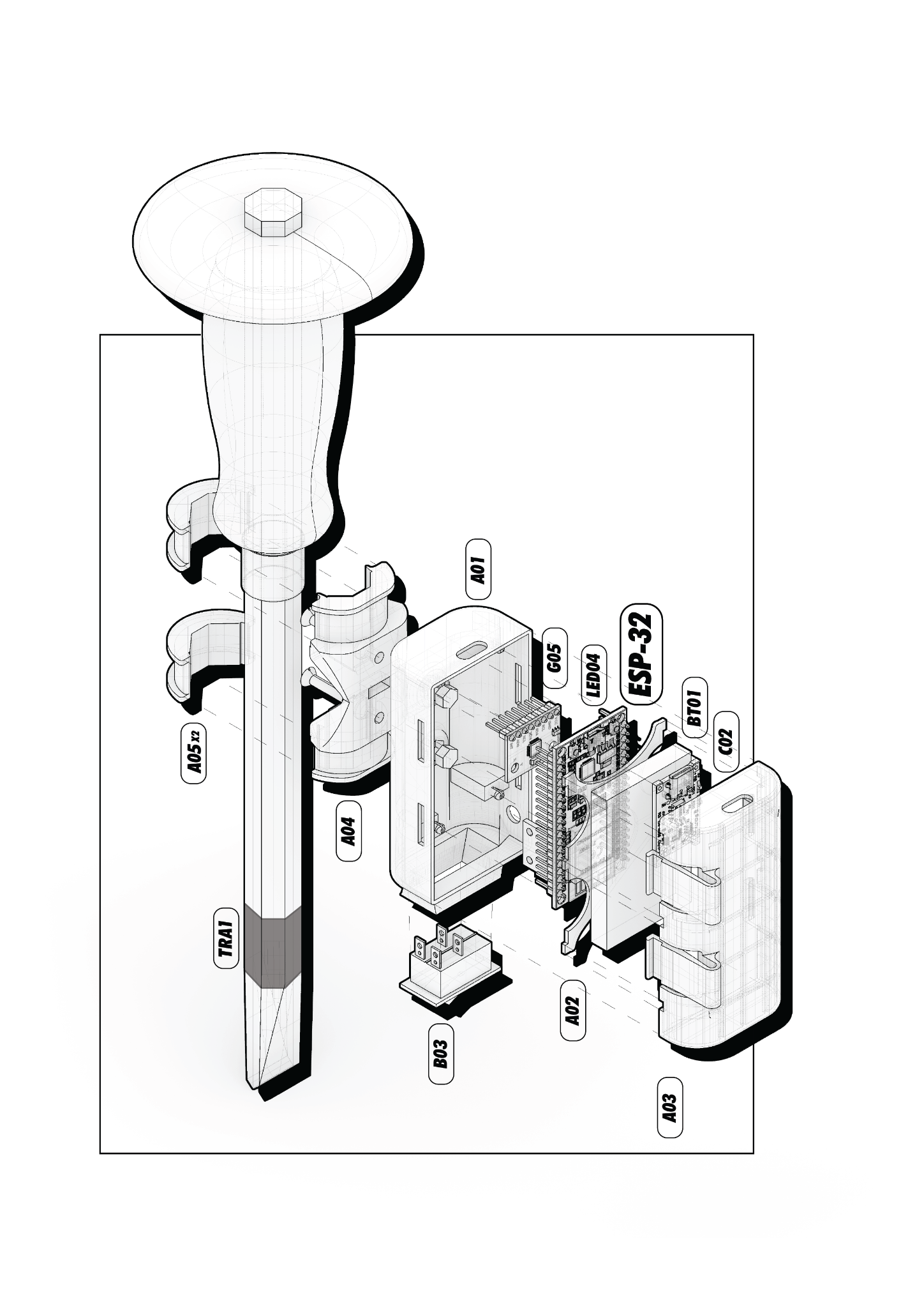
6. System Architecture
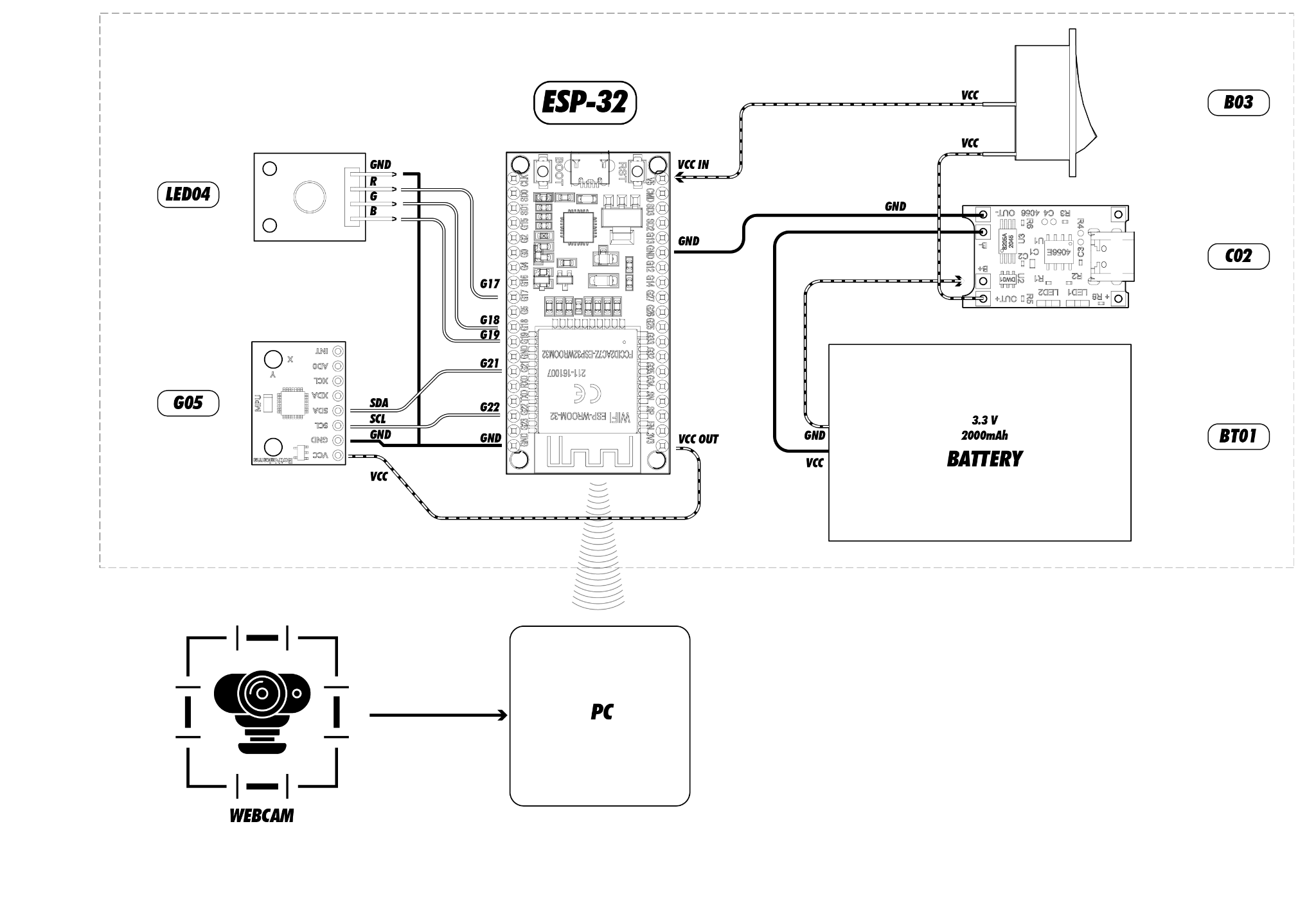
ESP-32 (Microcontroller)
○ Reads data from the MPU6050 (G05) sensor
○ Displays output via LED04 (RGB LED)
○ Transmits data to the PC via Wi-Fi
G05 – MPU6050 Sensor
○ 3-axis Gyroscope and 3-axis Accelerometer sensor for motion tracking
LED04 (RGB LED)
○ Controlled by the ESP-32 for status indication
Power Supply (BT01, C02, B03)
○ C02 (Charging Module): Charges the BT01 (Lithium-Ion Battery)
○ B03 (Rocker Switch): Controls power distribution
Webcam
○ Captures 4-dimensional video data and transmits it to the PC via USB
Computer
○ Reads Wi-Fi transmitted data from the ESP-32
○ Receives serial data from the webcam via PySerial
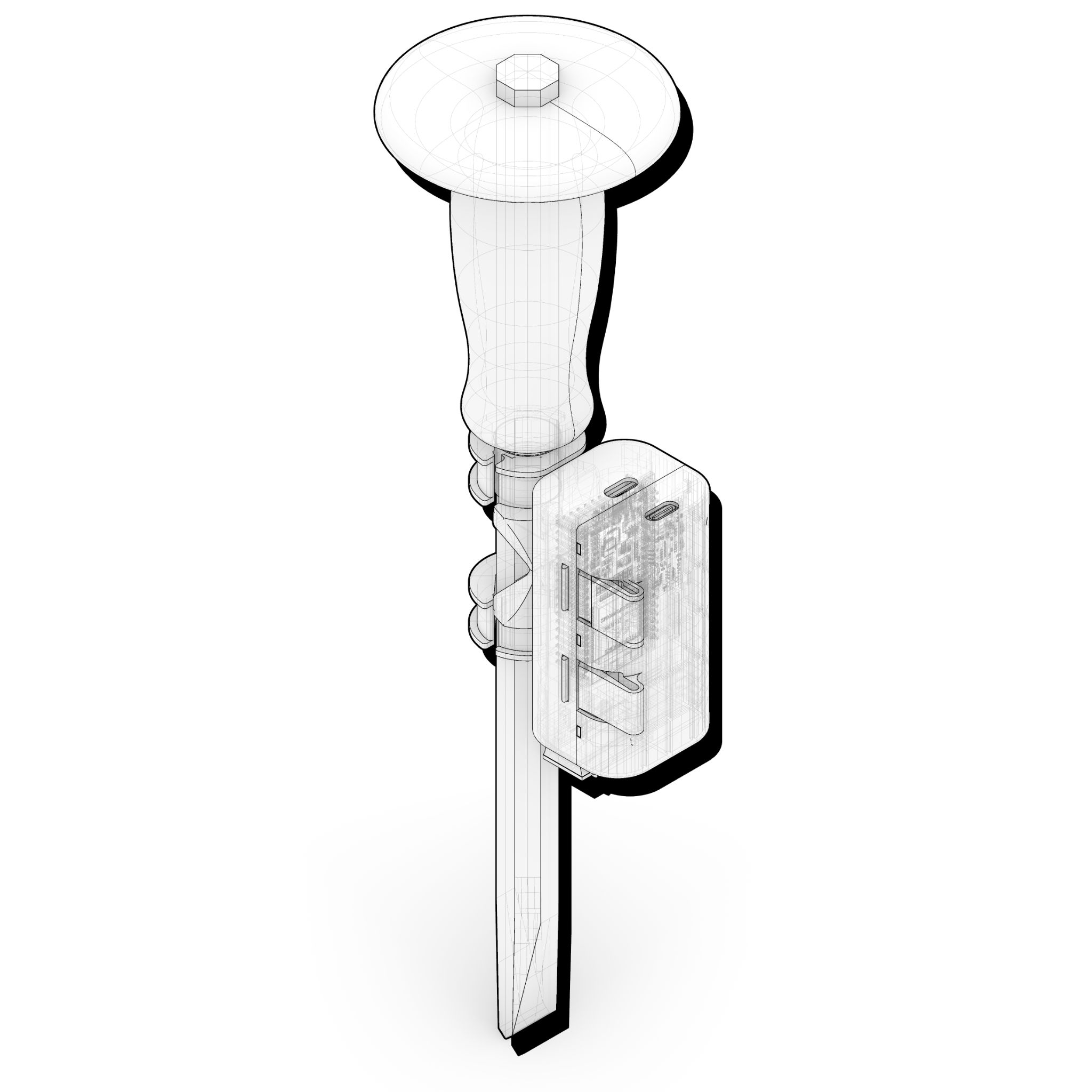
7. Hardware Overview
MPU6050 – Working Principles
Accelerometer
The accelerometer in the MPU6050 measures linear acceleration along the X, Y, and Z axes, capturing motion, tilt, and gravity. It operates using the piezoelectric effect, where internal masses shift under acceleration, generating electrical signals proportional to the force.
Gyroscope
The gyroscope measures angular velocity around the X, Y, and Z axes to track rotation and orientation. It works using the Coriolis effect, where vibrating masses deflect under rotation, producing signals proportional to the rotational speed.
Webcam – Working Principles
Camera
The Camera captures visual data by converting light into digital signals, providing video frames in real-time. It operates using a CMOS (Complementary Metal-Oxide-Semiconductor) or CCD (Charge-Coupled Device) sensor, where incoming light is focused onto an array of photodiodes. These photodiodes generate electrical signals proportional to the intensity of light hitting each pixel.
8. Communication
Protocols and Connections
- I²C (MPU6050 → ESP32): Sensor transmits angular rotation and acceleration data to the microcontroller via SCL and SDA lines.
- WiFi + TCP/IP (ESP32 → PC): ESP32 sends sensor data to the PC over WiFi using Python’s socket for reliable communication.
- USB + UVC (Webcam → PC): Webcam streams video to the PC via USB for processing in OpenCV.
- Power (Battery → ESP32 via TP4056): Lithium-ion battery powers the ESP32, with the TP4056 managing safe charging through analog control.
Data Produced
- Gyroscope Data (from MPU6050):
- Angular rotation values (roll, pitch, yaw).
- Output: Timestamp, Rotation X, Rotation Y, Rotation Z
- Computer Vision Data (from OpenCV):
- Pixel coordinates of the chisel markers.
- Output: Timestamp, Pixel_X, Pixel_Y
9. Software Stack
- Python: Handles data processing, visualization, and storage.
- Libraries used: OpenCV
- Arduino IDE: Programs the ESP32 to gather sensor data and transmit it via serial communication.
- Libraries used: Kelman
- Microsoft Excel / CSV: Stores synchronized data for further evaluation and integration into CAD software like Grasshopper.
Data Flow
- The ESP32 reads data from the MPU6050 sensor and transmits it to Python.
- Python processes and visualizes the data while also logging it to an Excel file.
- OpenCV captures and processes color-tracked movements from the webcam.
- Both data sources are merged for analysis and potential design applications.
.
10. Demo
11. Data Visualization
12. Limitations
2D Tracking Limitation
○ The system is currently designed to capture motion in two dimensions, relying on the screen window size for tracking.
Lighting Sensitivity in Color Recognition
○ The color markers used for chisel tracking are highly sensitive to lighting conditions. Changes in the lighting spectrum outside the controlled test environment can lead to recognition errors.
Camera Quality and Frame Rate Constraints
○ The webcam has limited resolution and frame rate, affecting the accuracy and sensitivity of color tracking.
○ Lower frame rates may cause motion blur, reducing the effectiveness of tracking fast chisel movements.
Parallel Positioning Requirement
○ The chisel must remain parallel to the recording plane for clean data collection.
○ Any deviation from this plane can introduce tracking inconsistencies, leading to inaccurate motion analysis.
Scaling Issues
○ The system outputs pixel-based coordinates, lacking real-world scaling (e.g., centimeters or millimeters).
○ This limits the ability to directly correlate motion data with physical dimensions.
Encapsulation Design Constraints
○ The current 3D-printed casing is compact and protects electronic components but lacks flexibility for mounting on different chiseling tools.
13. Future Improvements
To enhance the system’s functionality and efficiency, the following improvements are proposed:
Improved Casing Design
○ Redesign the 3D-printed casing to allow better accessibility to components, such as the reset button.
○ Ensure the casing can be mounted on various tools without compromising performance.
3D Motion Tracking Implementation
○ Upgrade the OpenCV tracking system to enable 3D geometric coordinate tracking.
○ Integrate depth estimation techniques to capture the precise position of the chisel in any orientation.
Integration of Depth and Multiple Cameras
○ Introduce a depth-sensing camera (e.g., Intel RealSense) to improve positional accuracy.
○ Add an additional camera at a different angle (Z-axis) to provide more accurate spatial positioning.
○ This will help overcome the parallel positioning limitation and allow better tool tracking.
Coordinate Scaling Improvement
○ Implement calibration techniques to convert pixel-based tracking data into real-world measurements (e.g., centimeters).
○ Ensure seamless integration with CAD and fabrication workflows for more precise robotic processing.
14. Conclusion
This project demonstrates the potential of integrating traditional craftsmanship with robotic fabrication by capturing and analyzing chiseling motion through computer vision and motion sensors. By combining real-time tracking with sensor data, we bridge the gap between human expertise and automated precision, enabling more responsive and intelligent robotic tool paths.
While current limitations exist, future improvements—such as 3D motion tracking, depth integration, and real-world scaling—will enhance accuracy and expand practical applications. This research lays the groundwork for advancing digital fabrication techniques, preserving traditional knowledge while embracing the possibilities of automation and robotics.
