
This project presents the design of a parametric pavilion for Plaça de Sant Jaume in Barcelona, inspired by the human towers of the castellers. A pattern of ellipses and circles was used as an allusion to the supportive hands and shoulders that form the tower. The pavilion’s base geometry responds to the plaça’s shape, entrances, and circulation, while referencing the verticality of a castell. Designed as a modular system, the pattern was mapped onto the surface of the base form, revealing the complexity of aligning logic with geometry. Our key insight is the need to define structural logic early on; establishing clear rules enables a design that is both coherent and flexible, allowing creativity to thrive within intentional and purposeful boundaries.
Design Concept
Plaça de Sant Jaume, located at the civic heart of Barcelona, is a historic square framed by the City Hall and the Palau de la Generalitat. It serves as a venue for political gatherings, cultural festivals, and civic events. Among these traditions is the performance of the castells, the iconic human towers of Catalonia. We intended to design a pavilion with: (1) a pattern that alludes to the trust and communal spirit of the castellers, and (2) a base geometry that rises from a stable, grounded base into lighter, ascending layers.
Pattern Design
Figure 1 shows the image from which our design was based. We intentionally chose to make an implicit rather than an explicit reference to this image. As such primitive ellipses and circles were used to form the human structure.
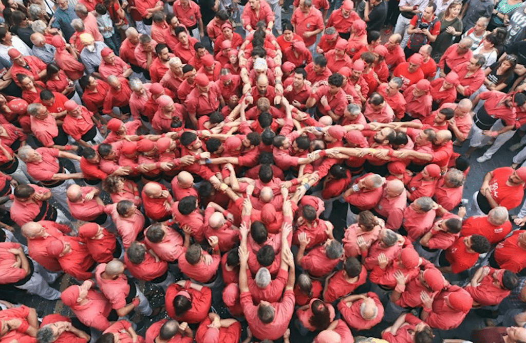
Figure 2 shows how our design evolved. We started with two concentric ellipses of different focal lengths to represent arms that are holding onto each other. Then added a circle that is moved to the side to represent the head.
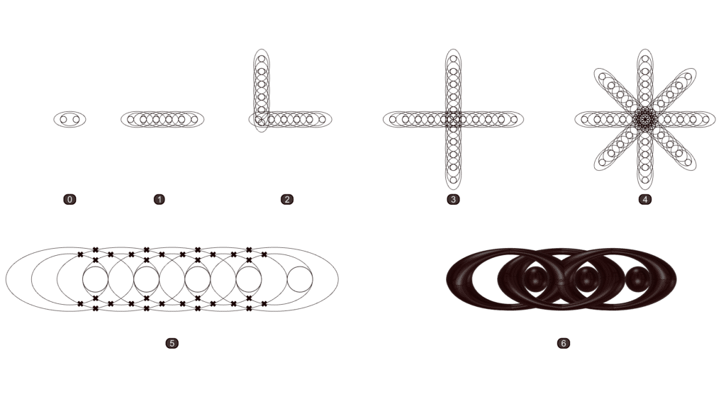
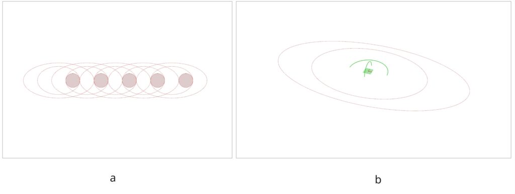
We then created a linear array of the initial pattern and created surfaces around them. We preferred using surfaces over solid breps to hypothetically save on computational power. Furthermore, we preferred to only create the surfaces on the top half of our construction plane. For the circle, instead of creating a sphere, we decided to create an arc and then sweep that arc onto another arc that is 0.5x its radius to create a hemisphere (see Figure 3b).
We did not want the surfaces (aka the “arms”) to intersect each other. Instead we want them to look like they’re interlinked. If we look at the array from right to left and divide the geometry into its top and bottom halves, the top half will be the “right arm” and the bottom half will be the “left arm”. We want the “right arm” to go over the “right arm” of the next “person”, and the “left arm” to go under the “left arm” of the next “person”. Using Curve|Curve to find the intersections within moved copies of the same dataset and then using Shatter to split the curves and then specifically trim the ones that we didn’t want proved to be a tedious task.
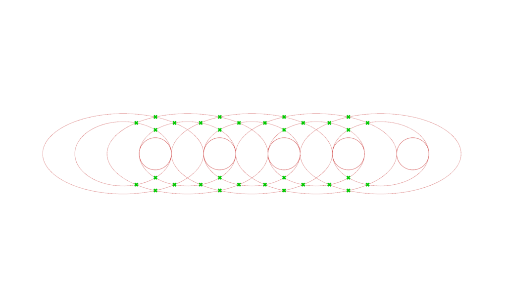
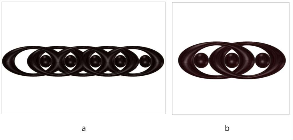
An simpler approach was just to tilt (rotate) the ellipses in alternating directions, much similar to an interlinked chain. We chose rotation angle to be just enough to avoid intersections as a surface is swept along each pair of ellipses. We used an arc to sweep along the two ellipses. The arcs are also rotated in the same angle as the ellipses (see Figure 5b).
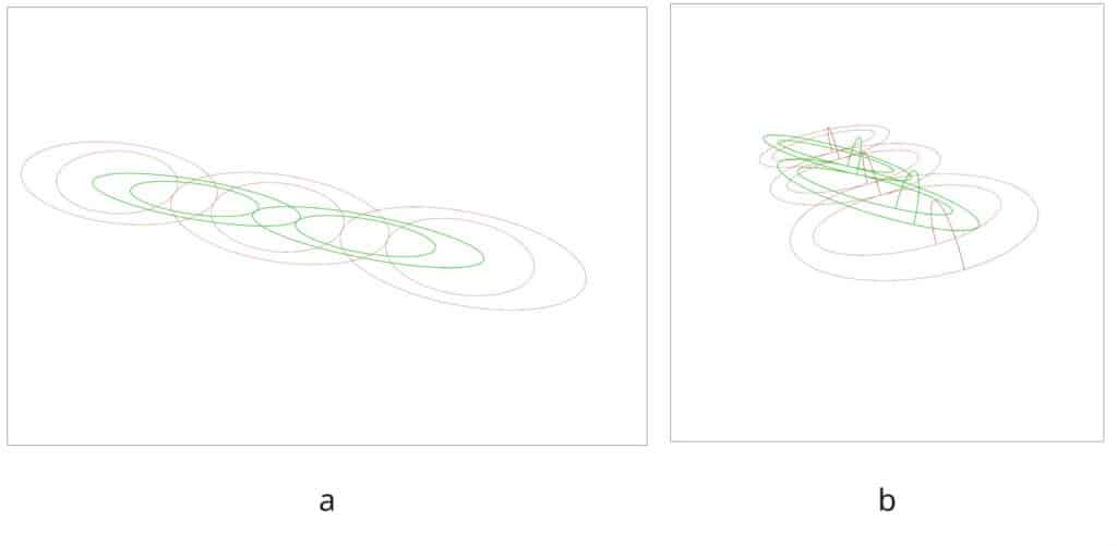
Figure 6(a) shows the resulting pattern which we can then rotate every 90° to create the cross pattern shown in Figure 1. To make it modular, we needed at least two links of the chain, tilted in opposite directions, as shown in Figure 6(b).
Base Geometry Design
Curve Definition: Set initial curve with openings for accessibility. Set Secondary and third curves for verticality.
Lofting and Twisting: Loft the three curves. Twist the base curve so that the geometry finds its initial verticality in the middle, just like the castells.
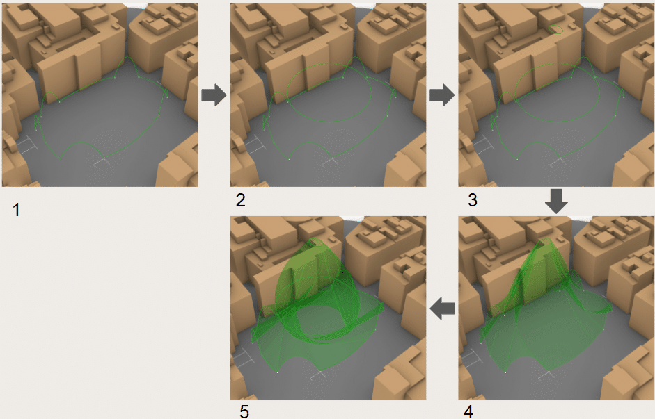
Dividing the surface: Set 3 divisions with Deconstruct Brep guided by the initial divisions of Interpolate that generated the initial curve. Divide the strips generated with List Item based on the function.
Piping and Orienting: The first and second strip receive special iterations due to their nature. The third strip is just transitional. The first strips get a reticular surface with isotrim, the second get the import of the pattern inspired by the castells.
Placing the Pattern onto the Base Geometry
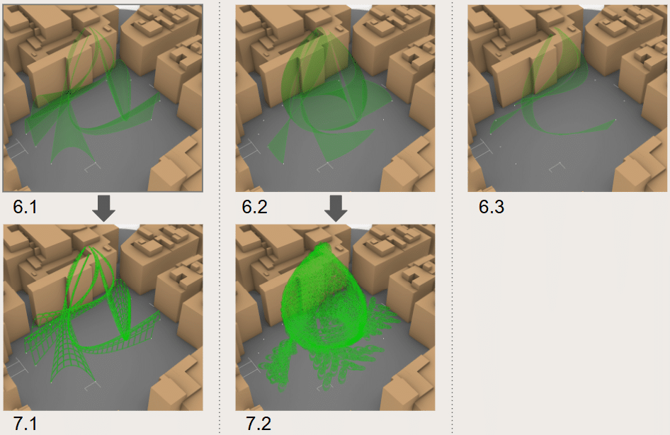
Hypothetically, we intended to “unroll” the surface of the base geometry, divide it into points and create the two-point modular castell pattern onto every other point of the base geometry. We will then “roll” the surface back onto the shape of the base geometry.
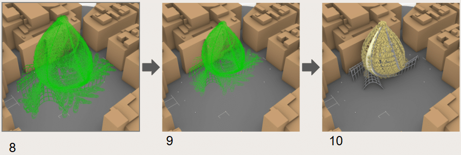
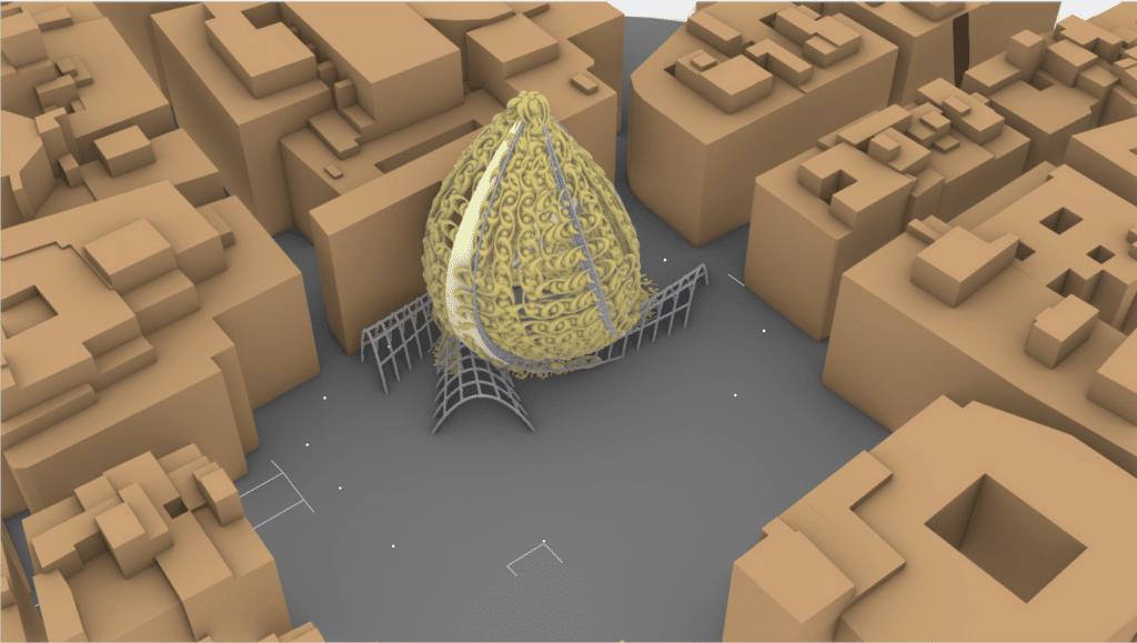
However, due to the complexity of the base geometry, the process became difficult to implement. Instead, the pattern was matched to each existing point on the base geometry without “unrolling” it. Parts of the base geometry that match the entrance/exit arcs were “skipped” so those parts remain open. Figure 9 shows the steps we took to arrive at our final output. Figure 10 shows our final pavilion.
Animation
An animation of how the castell pattern was created is shown in Figure . Each “cut” shows each step on how the final module was achieved. For cinematic purposes and clarity, the order of some steps were interchanged. For the duration of the animation, the location of the camera was moved to provide close ups on some detailed processes and zoom out when needed.

Lessons Learned
Placing the pattern onto our base pavilion geometry became a main challenge for us. While we did some planning the moment we decided to divide the task into pattern design and base geometry design, we had not considered the details that are relevant to actually putting them together.
The problem would not have existed in the extent that it did had we considered the details of attaching them down to the level of points. Better yet, it would have been a useful exercise to start with the end in mind. We could have started with a planar surface where patterns could be applied. And then take that surface as the starting points for our independent designs. Otherwise, any set of clear rules defined at the starting point would have solved most of our problems. The clear rules would have allowed us to create designs that are coherent and flexible, while allowing our creativity to unfold within those intentional and purposeful boundaries.
It also helped us to consider the animation process while designing our geometries. It clarified the step-by-step logic in a visual way of thinking and offered a fresh perspective that aided us in overcoming some of our design challenges.
