
The primary goal of this project is to design and fabricate a custom end-effector that can be attached to an ABB robot. The system that our group decided to explore involves the idea of utilizing an airbrush and robotically controlling it. This system will utilize a Raspberry Pi Pico for control and Grasshopper for generating and sending linework designs from Rhino software. The project aims to demonstrate innovative robotics applications in art and design, showcasing the synergy between digital fabrication and robotic automation.
Airbrush Anatomy, Mechanics, and Tests
The detailed design of the custom end-effector for the ABB robot was significantly informed by the intricate anatomy of the airbrush system. This intricate relationship between the airbrush components and the end-effector’s moving parts required careful consideration in several key areas:
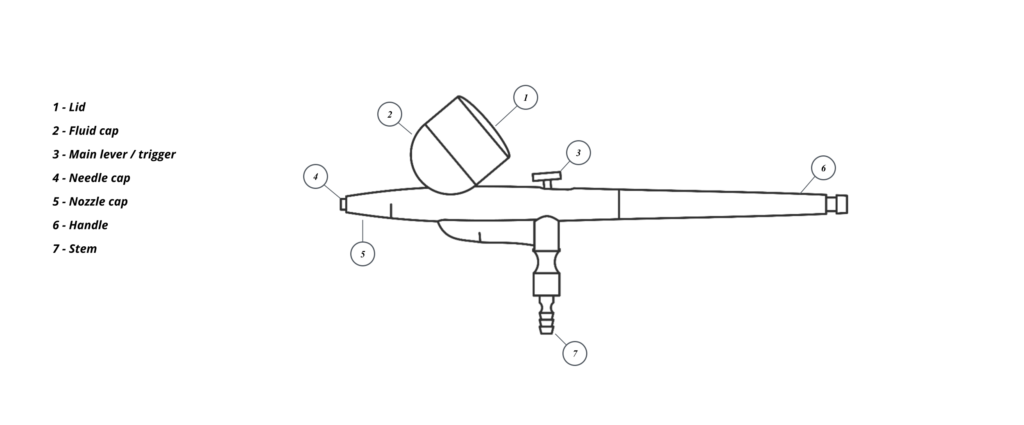
Figure 1 – Airbrush Anatomy
Dual-Action Control Mechanism: The airbrush’s control button is a sophisticated component that operates in two stages – pushing down to regulate compressed air and pulling back to control paint flow. The end-effector’s design had to incorporate a mechanism capable of performing both actions with precision.
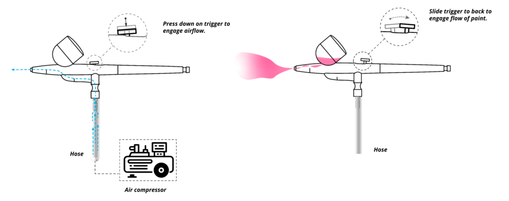
Figure 2 – Steps of Using an Airbrush
By utilizing the airbrush we came to understand how different positions can affect both the line width and the spray of the actual line being produced, assessments looking at distance from the painting surface, the angle in which the airbrush would be positioned and ink volume being deployed which would be considerations for further testing in conjunction with the robot.
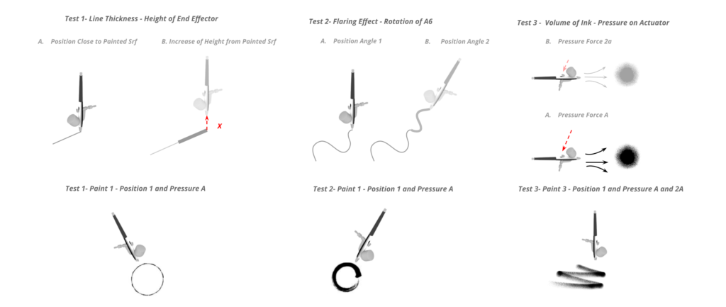
Figure 3 – Customization Tests
Initial Ideas and End-Effector Design
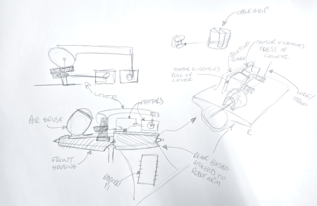
Figure 4 – Initial Ideas
Design for Pushing Down: The first action, pushing down, initiates the flow of compressed air. The end-effector needed a mechanism that could apply a vertical force to the button. This required a linear or similar actuator that could be precisely controlled to exert the right amount of pressure on the button, mimicking the downward press. In our case we decided on utilizing a 3d printed linear actuator that would allow for a 3D printed finger to push this button.
Figure 5 – Linear Actuator Activation – Motor 1 (Air Pressure On)
Design for Pulling Back: The second action, pulling back, controls the paint flow. This required a more complex mechanism, as pulling back involves a different axis of motion. The design could include a set of gears and levers that could translate the robot’s motion into a backward pull on the button. This system had to be finely tuned to ensure it could vary the paint flow based on the extent of the pull, which is essential for different painting techniques. In this case we utilized a servo with a fishing line attached to a button cap that would allow for controlling the distance of pull through the rotation angle of the servo.
Figure 6 – Motor 2 (Air Pressure On)
The overall fitting tolerances of the end-effector were critical. The design had to ensure that all parts of the airbrush, including the nozzle, hose connections, and any external controls, were accommodated without causing strain or misalignment. Additionally, as the robot and the end-effector moved, the internal components of the airbrush, such as the paint chamber and the mechanism controlling paint flow, had to remain functional and stable. This required a deep understanding of the airbrush’s internal mechanics and how they would interact with the varying orientations and accelerations of the robotic movements.
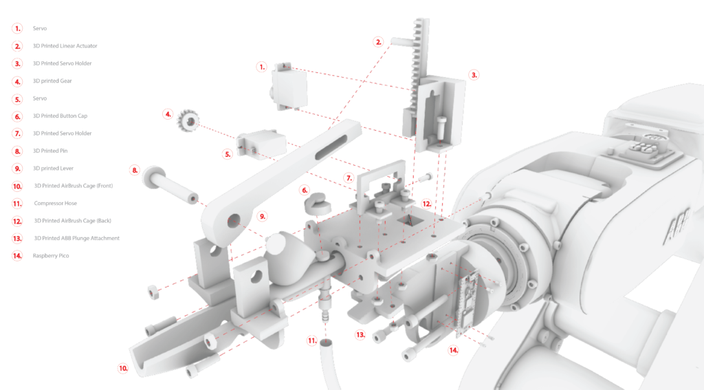
Figure 7 – Exploded Axonometric of AirBrush End Effector
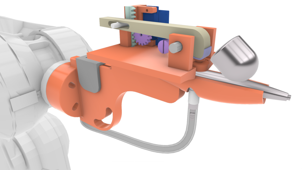
Figure 8 – Isometric Front of System
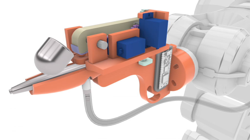
Figure 9 – Isometric Back of System
Design of the Electronic System
The electronic system has been designed to support both motions and generate a range of forces for each. The first servo (linear actuator) is controlled by two inputs from the robot, resulting in four combinations (00, 01, 10, and 11). These are then translated into angles to set the servo. The same logic applies to the second servo. However, due to a larger pulling range, we opted for four inputs, resulting in 16 different combinations/angles.
The combination of both servos allows maximum control over paint and airflow, enabling thorough research for optimal outcomes.
The diagrams below illustrate how this circuit will operate. The first depicts the testing phase, during which we utilized an Arduino Uno and switches to activate the motors. The second diagram provides a detailed overview of how the Raspberry Pi Pico is connected to the ABB IRB 120 robot.
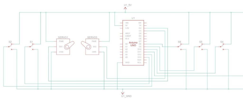
Figure 10 – Circuit Scheme
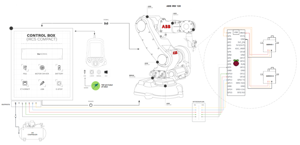
Figure 11 – Robotic Setup Diagram
Figure 12 – Design and Eletronics Process and Assembly on Robot
From Tests Setups to Initial Results
According to our three first hypotheses, grasshopper tests were conducted in order to test how the end-effector would behave with geometrical and motor gradient variation. The following tests were performed, which included a non planar circle, with constant pressure and paint flow, a planar circle with differing angles at each point and a spline curve that would receive information on rotation of servo at each point.
TEST 1
For this particular test, the primary goal was to analyze how variations in the Z-axis, involving both the base and the end-effector, affect line thickness during the painting process. To achieve this, a circle was drawn and subdivided through points in Grasshopper that would allow for each point to have a different height (planes), serving as a robotic toolpath for the ABB robot. This setup allowed for a detailed examination of how changes in height (Z-axis values) influence the output of the airbrush, specifically in terms of the thickness of the lines it paints.
Figure 13 – Robotic Toolpath Test 1 – Height of EndEffector (Speed: 50%, Max Height: 70mm, Min Height: 10 mm)
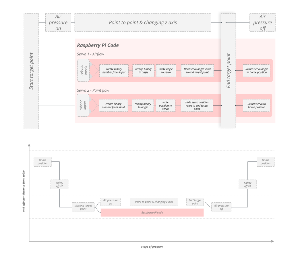
Figure 14 – Toolpath Logic and Servo Actuator Algorithm – Test 1
Figure 15 – Test 1 on Robot
The results of our experiment particularly in understanding how the color gradients in our airbrushed linework were influenced by the height of the end-effector, or the Z-axis positioning. We found that when the airbrush was held higher above the surface (increased Z-axis height), the linework appeared fainter. On the other hand, when we brought the airbrush closer to the surface, the linework became much clearer and more distinct. This makes sense because the shorter distance allows the paint to be applied more directly and densely, producing lines that are not only cleaner but also more vibrant in color.
Figure 16 – Test 1 Result
TEST 2
The test involving a planar circle took an interesting turn when we began altering the angles of the planes at each point. This modification was crucial as it allowed the airbrush, mounted on the robotic end-effector, to mimic movements that are more akin to those made by a human artist.
Initially, with a standard planar circle, the movements of the robot and airbrush were relatively uniform and mechanical. However, by introducing varied angles at different points along the circle, we added a new dimension of complexity and realism to the robot’s motion. This adjustment meant that the airbrush wasn’t just moving in a flat, two-dimensional plane; instead, it began to navigate through more dynamic, three-dimensional space, much like how an artist’s hand would move over a canvas.
Figure 17 – Robotic Toolpath Test 2 – Flaring Effect A6 Rotation (Speed: 50%, Max Height: 10mm, Angle Deviation: +-30 mm)
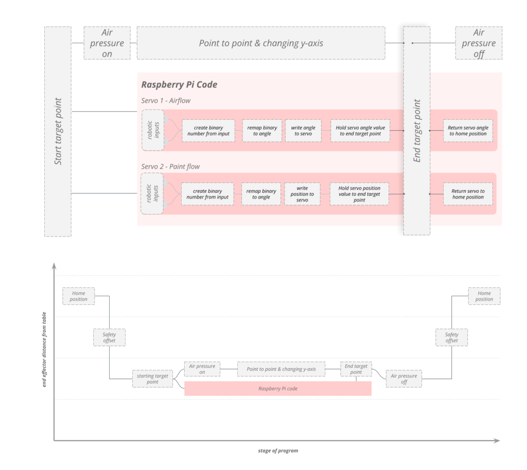
Figure 18 – Toolpath Logic and Servo Actuator Algorithm – Test 2
Figure 19 – Test 2 on Robot
The adjustment of the angles at different points in our experiment led to an intriguing outcome: instead of the intended perfect circular patterns, the robotic airbrush system produced an ellipse, indicating slight deformations in the execution of the toolpath.
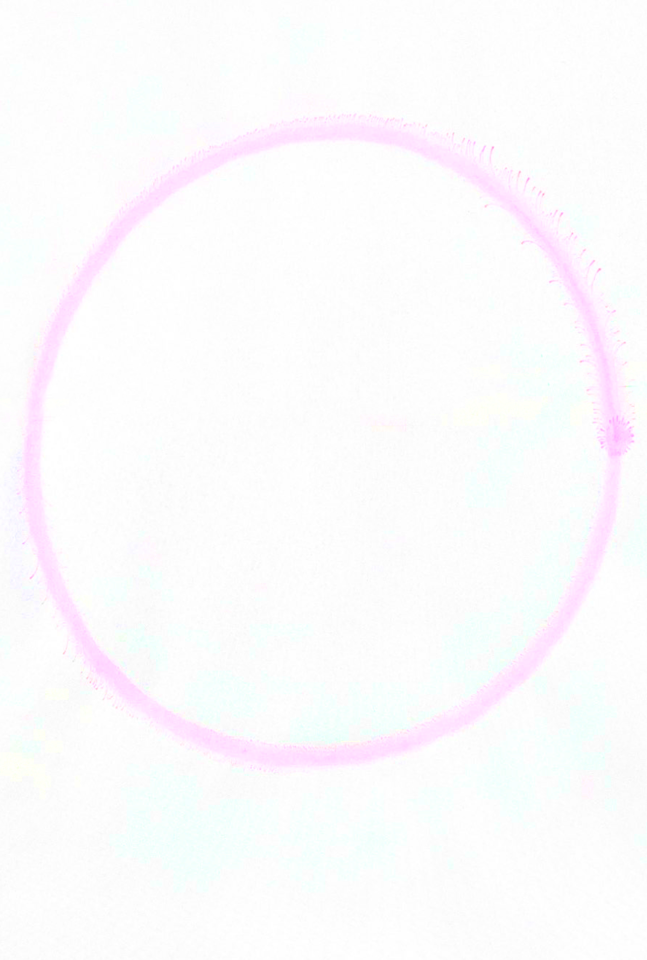
Figure 20 – Test 2 Result
TEST 3
In this test, our primary aim was to examine how the density of ink applied by the airbrush varied along a predetermined curved path, depending on the gradient of forces exerted on each point. We hypothesized that varying the force applied to the points would result in different line thicknesses being printed along the curve.
To achieve this, we established a unique set of values for each digital output at every point along the curve. These values were determined based on a binary combination feedback system orchestrated by the Raspberry Pico program. This feedback was crucial in informing us how the servos should be adjusted at each point to achieve the desired variation in line thickness.
Once we had these servo settings, we integrated this data into our Grasshopper file. This step was essential for converting the servo adjustments into input/output commands for our robotic toolpath simulation. Essentially, the Grasshopper environment acted as the interface where the physical adjustments of the servos, as determined by the Raspberry Pi Pico’s programming, were translated into the robotic arm’s movements along the curve.
Figure 21 – Robotic Toolpath Test 3 – Volume of Ink (Speed: 12%, Max Height: 10mm)
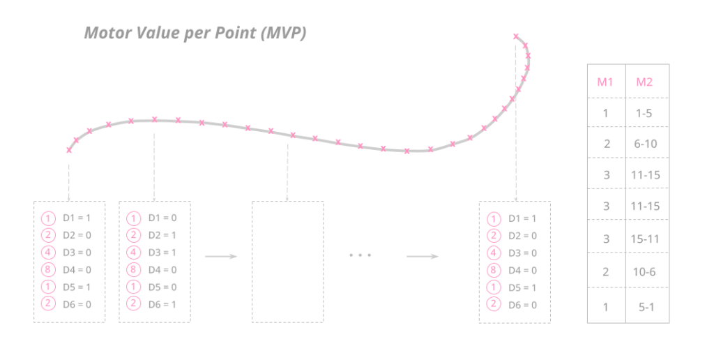
Figure 22 – Motor Value per Point (MVP)
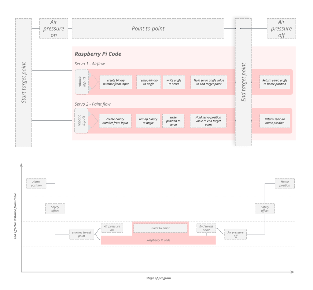
Figure 23 – Toolpath Logic and Servo Actuator Algorithm – Test 3
Figure 24 – Test 3 on Robot
Our expectation was that by carefully manipulating the forces applied to the servos at each point of the curve, we would be able to create a gradient of line thicknesses, ranging from thin to thick. This experiment was not just about testing the precision of our robotic system but also about exploring the artistic possibilities that such precise control could unlock. By understanding how to manipulate ink density through servo adjustments, we hoped to add a new dimension of creativity to our robotic airbrush system.
The results were quite captivating, although we unaccounted for a misuse of speed in the robotic file and ran much slower than was supposed to which gave us a higher concentration of paint than expected.
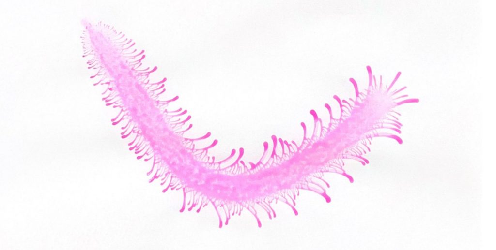
Figure 23 – Test 3 Result – Caterpillar
Future Applications
Further possibilities to explore involve tailoring non-planar sculptures and efficiently designing color gradients in Grasshopper, seamlessly transferring them to physical objects. Industries like automotive and Hollywood special effects heavily depend on airbrush techniques to craft characters for TV and film, making automation a gateway to new innovations. In mosaic-rich areas like Barcelona, this technology could revolutionize the customization of glazing and painting on ceramic pieces. This versatile tool could also be employed to craft personalized artwork and murals, expanding its creative applications.
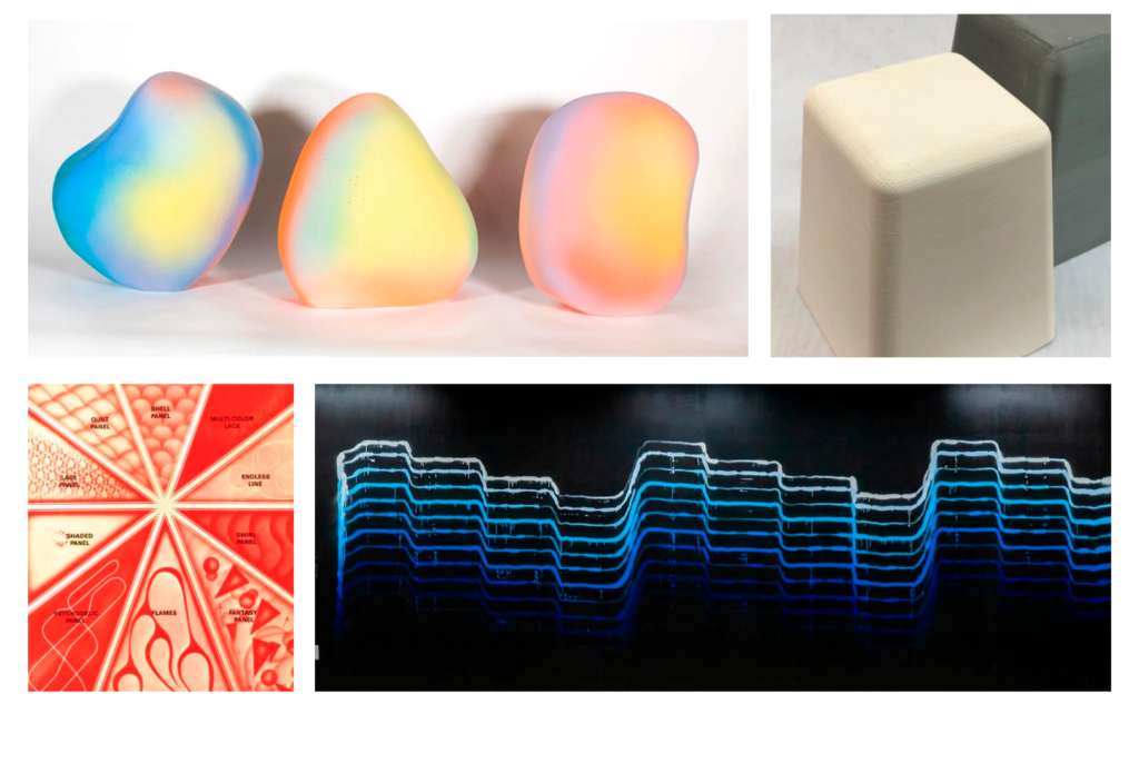
Figure 24 – Possible Applications
Further Steps
Considerations for future improvements:
Comprehensive Redesign: Reevaluate various elements such as motor positioning, Raspberry Pi placement, and input/output configurations. The outcomes of our trials indicate that the current number of paint flow combinations may be excessive. Additionally, exposing the Raspberry Pi to paint and dust poses a risk of reducing its lifespan. To address this concern, it is advisable to implement protective measures, such as covering the Raspberry Pi.
Upgrade to Reliable Hardware: Consider transitioning to more dependable hardware options, such as a professional-grade linear actuator, to enhance system reliability.
Lightweight Design Optimization: Explore lightweighting techniques, such as topology optimization, to enhance the overall efficiency of the design and reduce 3D printing times.
Direct Ink and Air Flow Supply: Explore the development of an alternative design that directly supplies ink and air flow, similar to the SAMES KREMLIN A28. This approach would enable enhanced automation capabilities and streamline the painting process further.
Figure 25 – SAMES KREMLIN A28
To access the printed parts to adapt and prototype/develop further here is the drive: https://drive.google.com/drive/folders/1BnI9a5Yxh5xVJUQQwkUMVpXJZemnGTa8?usp=sharing
