Concept
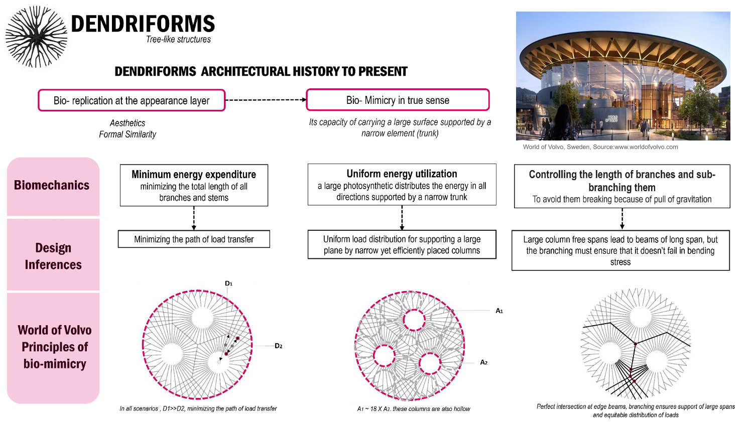
From historic times, dendridorms have been used as architectural inspiration. At first, they were just used for aesthetics, but soon they were used as a prototype of biomimicry. Our study is based on one of such examples, where the biomechanics principles of minimizing energy expenditure have been used to minimize the path of load transfer, and the principle of uniform energy utilization has been used to support a large photosynthetic surface by a narrow trunk.
Inspiration and pseudocode
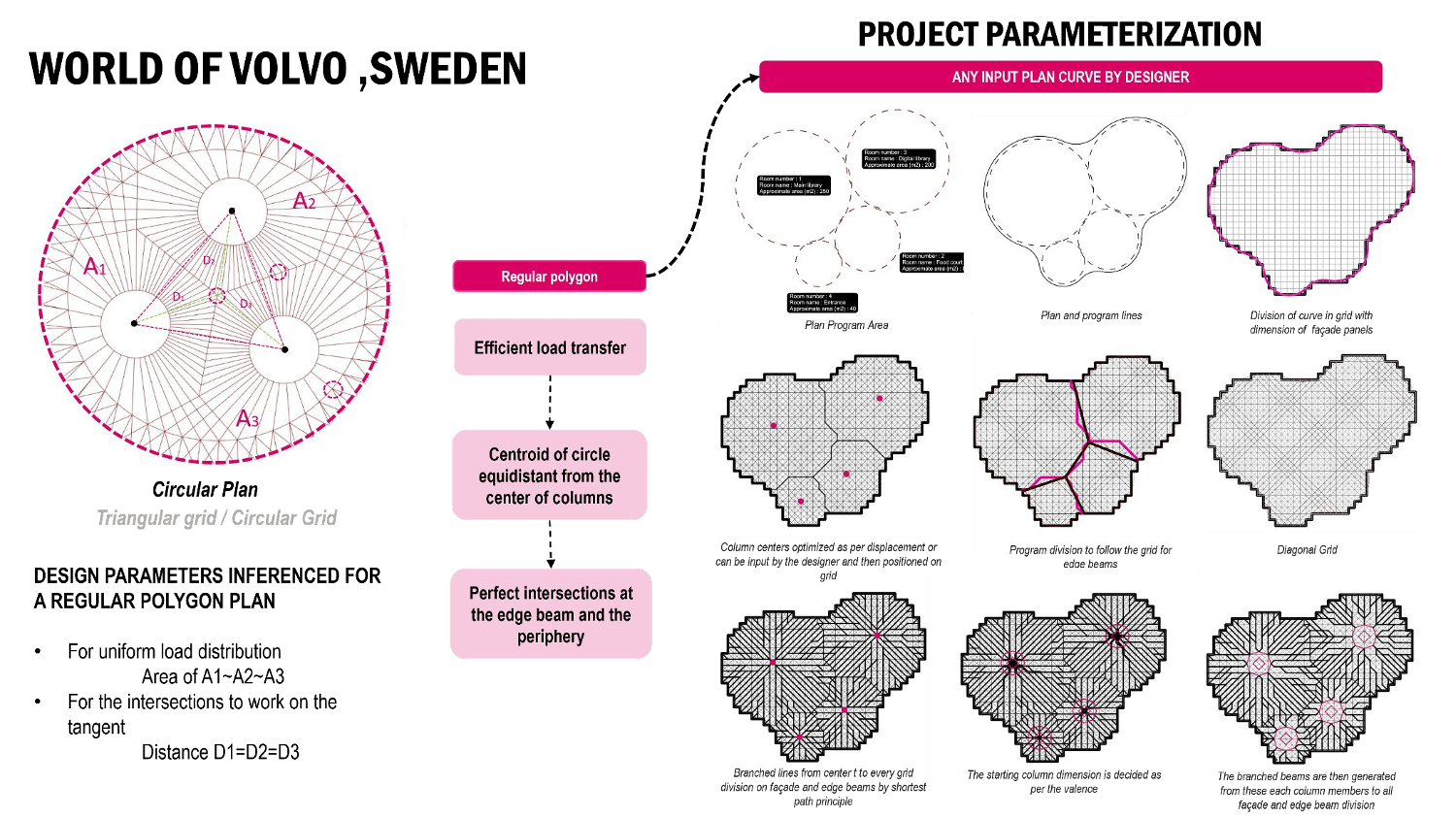
In our World of Volvo study, what could be inferred, is that as it’s a circular plan, areas are divided equally, and though the radiuses of the column may vary they are equidistant from the center. This principle can be extrapolated to any regular polygon to get those perfect intersections at the edge beams and at the façade.
In our project, we extrapolated this concept to work for any curve input by the designer. For the input, the designer uploads a CSV file with a program and then a curve is generated automatically, and one can move around the program as per their design. The curve is then split with a grid whose size is based on the input facade panel length. Then a diagonal grid is generated for the same. The program division is taken as the edge beam division of the roof slab and those lines are tweaked to follow the grid. Columns are placed at the center of these areas (their position can be optimized later) and then also aligned to the grid. Branched beams are connected from these centers to the facade, and edge beam divisions are created as per the shortest path via the grid.
System materialization
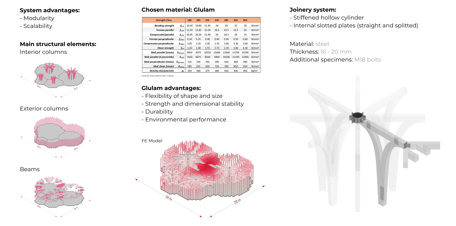
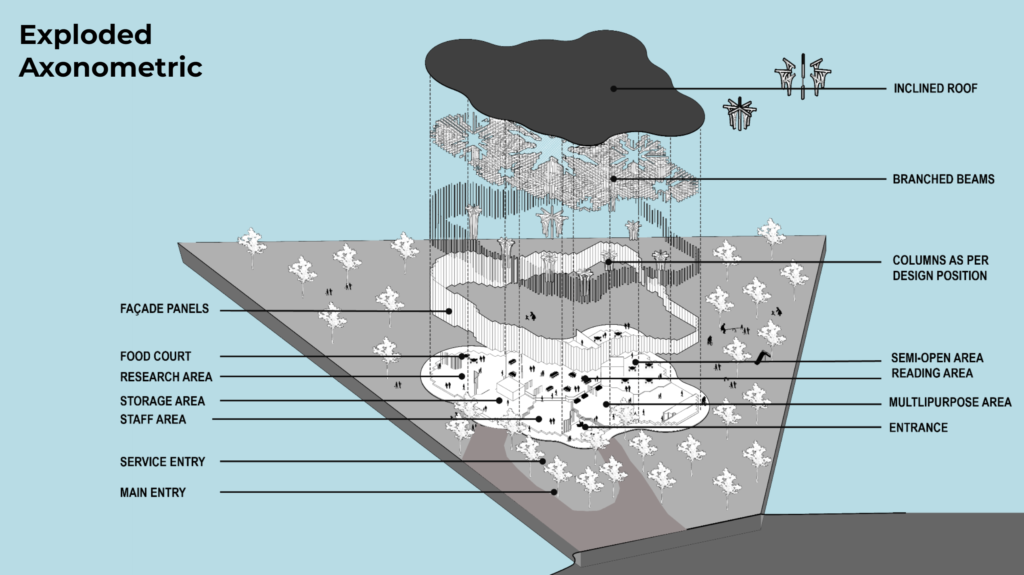
Even though the shapes that we work with are pretty fluid, thanks to the grid we were able to create a system that is modular and scalable, with the structural elements re-shaped to fit the guides. These elements are – main interior columns, supporting exterior columns, and dendriform beams. The beams can be split into two types based on the length – (placed on the grid diagonals or on the initial grid).
For the material of our main structure, we chose glulam, because of its flexibility, strength, durability, and environmental performance. For the joints connecting the structural elements, we decided to use mainly hidden connections, which are slotted plates (either straight or split) depending on the type of elements that they are connecting.
Flexible program creation
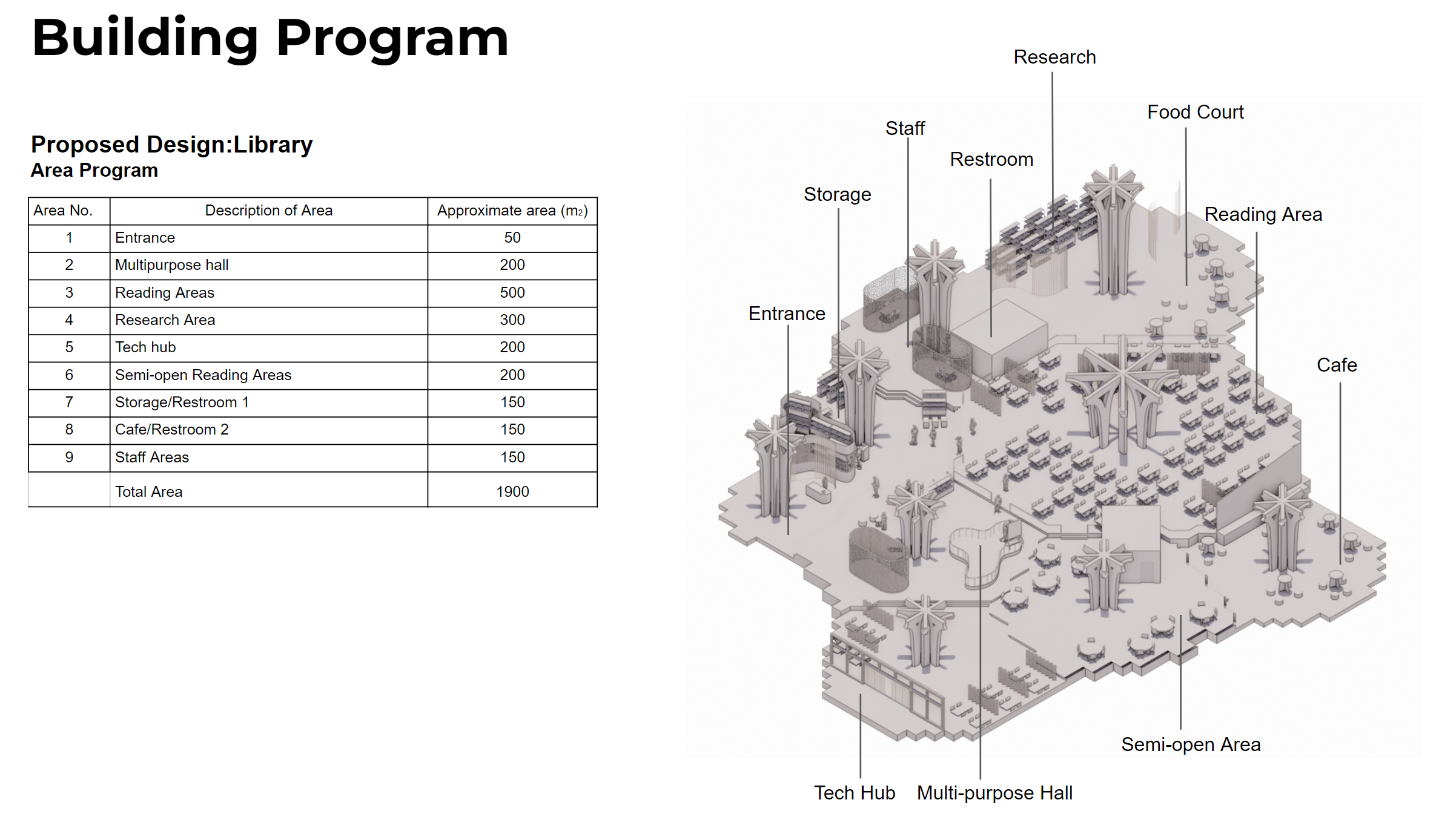
Because the structural system of our building is closely connected with our program, we wanted to start the parametrization of the project as early as possible. That’s why we incorporated a solution for the potential users to create a functional building program just from an imported .csv file with basic parameters such as room name and area. The program can be then manipulated and adjusted in the Rhino file.
Structure parametrization
After setting up the program the user would have several different parameters to manipulate, both in 2d and 3d. In 2d, we have different types of division grids and grid sizes as well as column placement and size. We also manipulated the weight of the grid for the shortest paths that create the beams, so the user could have different types of branching beams to work with. In 3d, we can set the floor height, roof slope and angle, roof height and cantilever as well as roof relaxation. All of these parameters can be both optimized or set manually by the user.
Contextualization
Material traceback
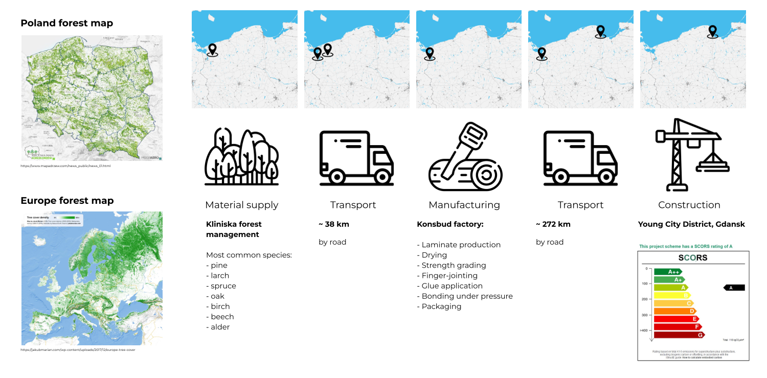
When it comes to the material used for our building, we took advantage of Poland’s well-developed forestry and wood fabrication industry. The material supply comes from the northern Polish forests and is processed closely to the source, by one of the biggest Glulam manufacturers in the region. After that, it’s transported to the site for construction. The estimated cost of our carbon footprint in regards to the SCORS rating is an A. This value could be a bit better, but because our system is quite timber-intense, to provide the necessary structural stability, we opted for larger elements at the cost of carbon footprint.
Architectural drawings
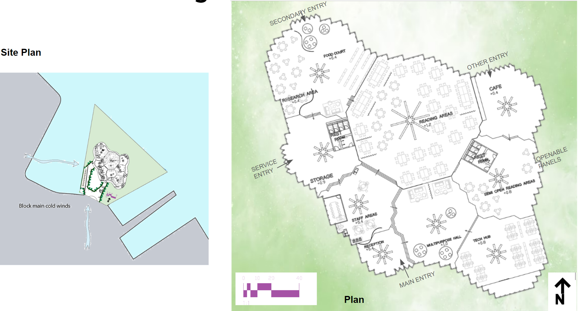
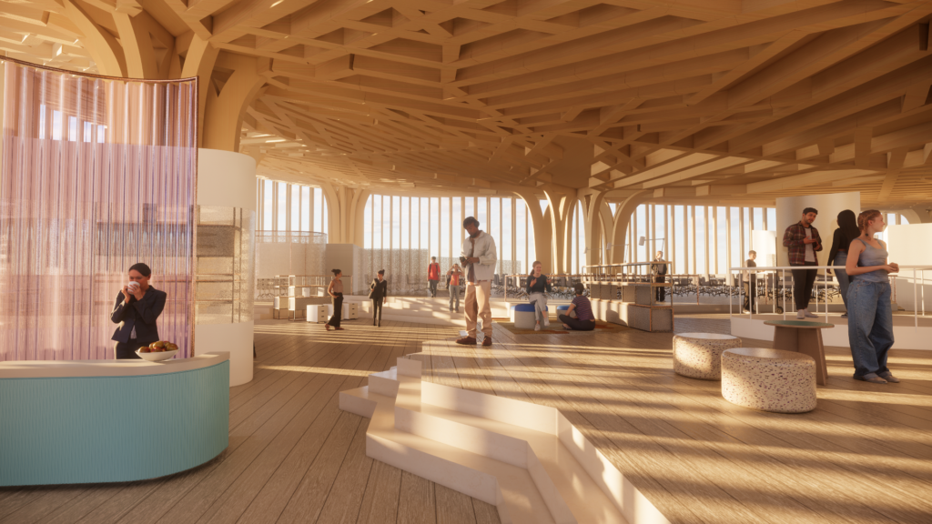
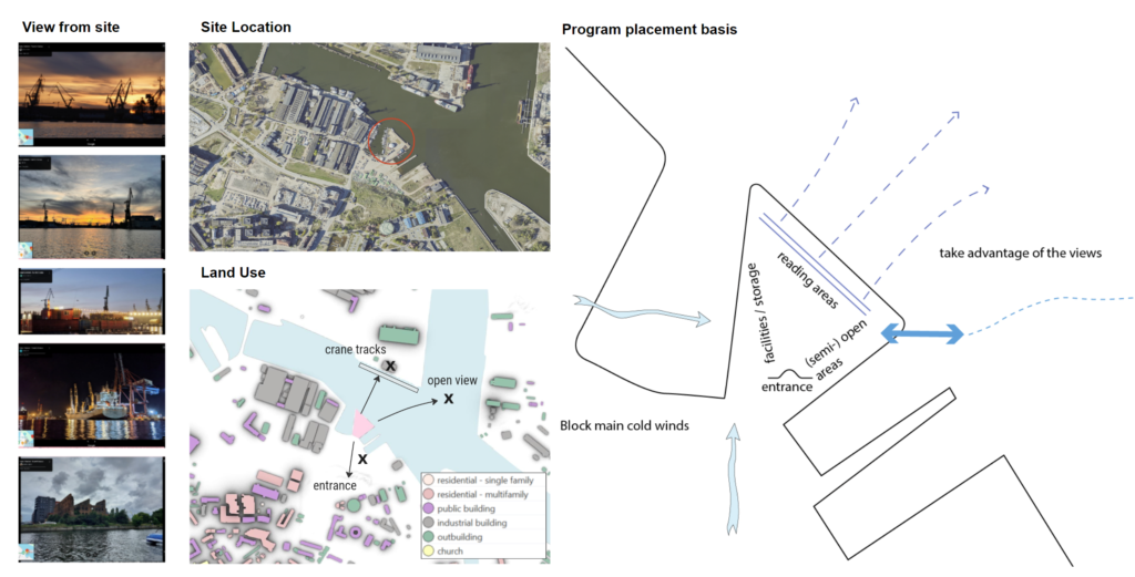
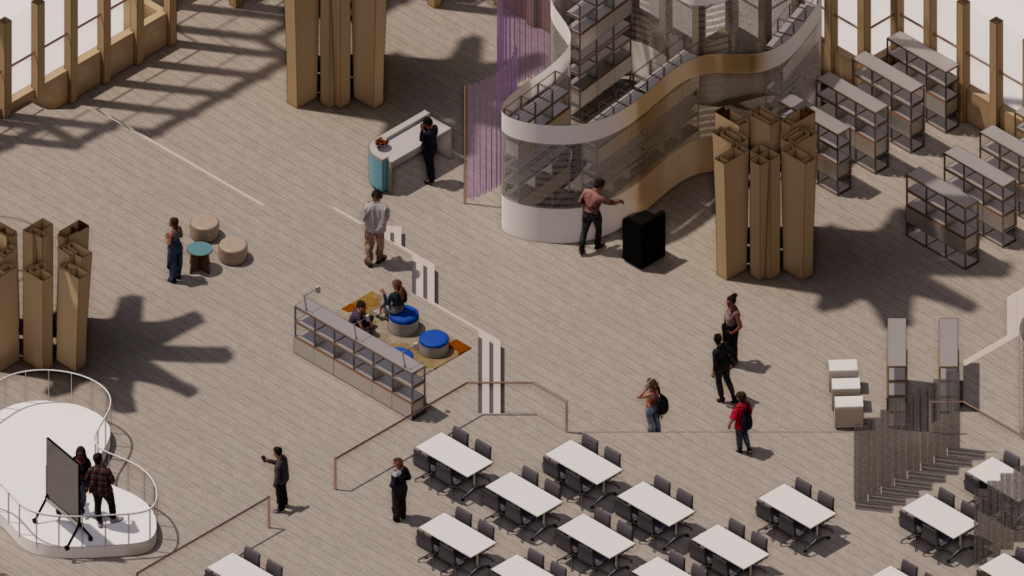
At the site, robust gusts sweep in from the west to the south-west, prompting a strategic design approach. To counteract the force of these winds, the planning commenced with the strategic placement of essential service areas like the staff room and storage facilities along this prevailing direction. Conversely, in the area where the wind exerts a gentler influence, we allocated spaces that could be partially or fully exposed. This includes versatile zones like the cafeteria, multi-purpose hall, and reading areas, tailored to harmonize with the prevailing climate conditions.
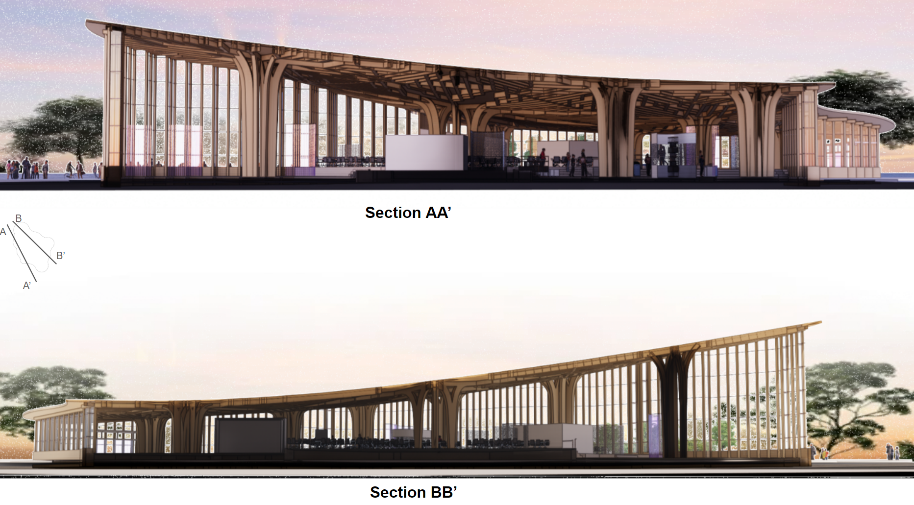
In the sectional analysis, we horizontally segmented the building, delineating variations in floor levels and heights based on usage and program requirements. The roof design was carefully crafted, featuring a slope towards the south to maximize the influx of sunlight into the building.