Concept
The architectural concept is based on creating a data center that expands over time, following a Design for Manufacturing and Assembly (DfMA) approach.
At the core of the design is a superstructure, populated by smaller modular data halls. These are supported by a service program that includes operational spaces, storage, and MEP systems, particularly cooling, which scales with the growth of the data halls.
The design emphasizes modularity, replicability, and construction feasibility, with its mechanical appearance reflecting the principles of assembly and disassembly.
:

Structural model workflow
Pseudo-code: Grasshopper > Monoceros module extraction > Geometry reconstruction in Grasshopper > Karamba Analysis
The transition from the architectural concept to the structural model was conducted using Monoceros in Grasshopper for modular aggregation. Following our topological map, the next step was to create a super-structure to host all the modules. The modules were aggregated using monoceros, a Wave Function Collapse (WFC) algorithm plug-in for grasshopper.
We selected one aggregation iteration and divided it into two geometries:
The data halls, generated computationally in Grasshopper.
The building shell, manually modeled in Rhino.
The geometries were simplified into columns, beams, and bracing elements for structural analysis. Using Karamba, we evaluated: 1- Cross-section optimization, to ensure material efficiency. 2- Structural integrity, identifying potential issues like buckling or connection errors. 3- This process provided a detailed understanding of the structural behavior and helped refine the modular components.
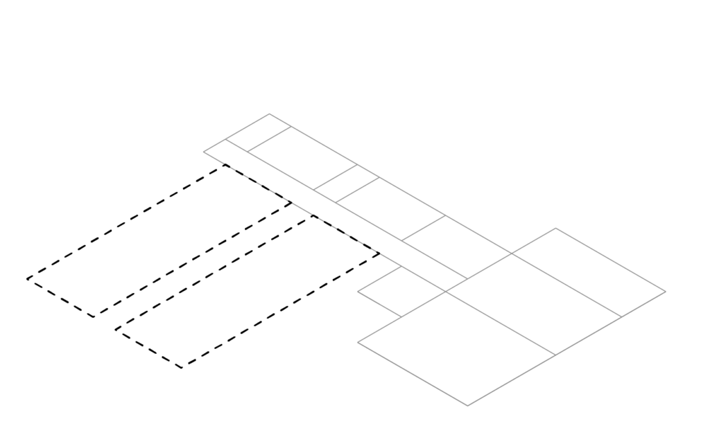
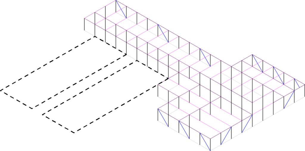
building (solid lines): rhino stick model
Structural Diagram

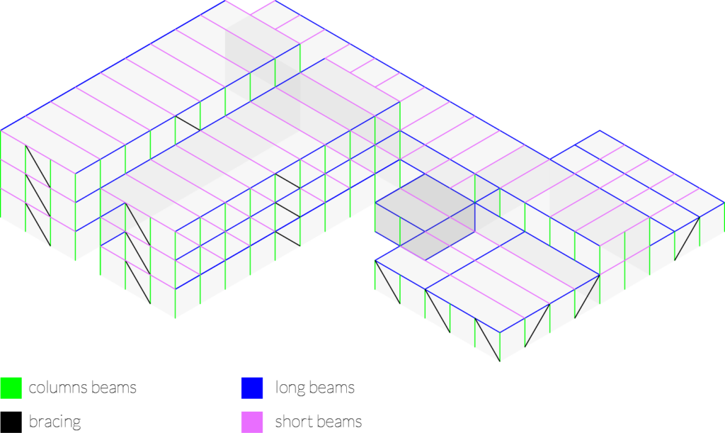
Data Hall: Structural Design & Optimization
The structural design of the data halls is based on a 4.5-meter column grid on the building’s perimeter leaving us with a open plan which would hosting different data server modules to be plugged-in.
In Grasshopper, we parametrized the column grid. This would have an effect not only in the column count, but also on the count of beams, bracing, and structural nods. This parametrization became a critical factor for optimizing the structure’s material use and environmental impact.
Different iterations of the structural members count would be analyzed to optimize and find the best solution.
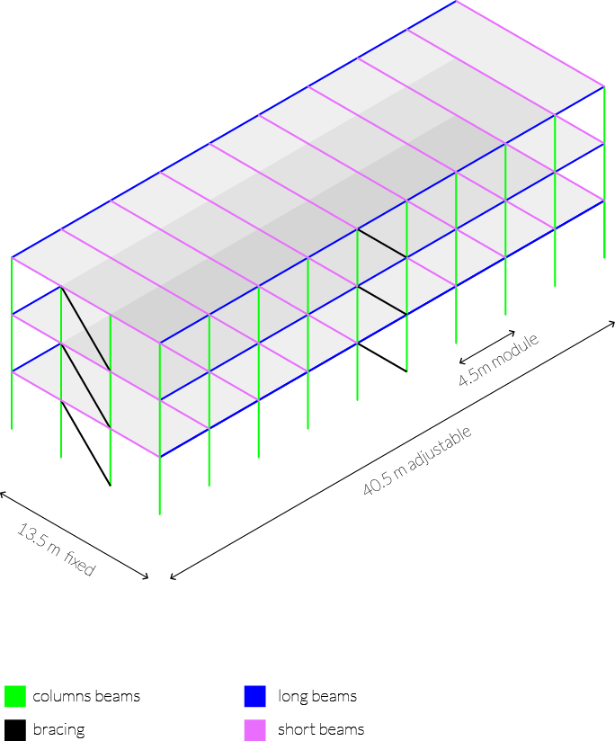
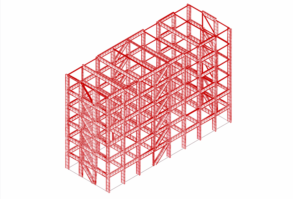
Optimization: Minimum of columns / structural members to reduce CO2 footpring, structure mass, & displacement
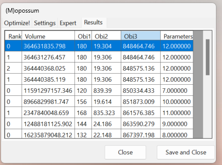
With a parametric structural system set up, working together between the structural members # count + Karamba’s Cross Section Optimizer, the next step was to optimize for 3 important variables:
1- column & structural members reduction
2- minimize displacement
3- minimize CO2 footprint.
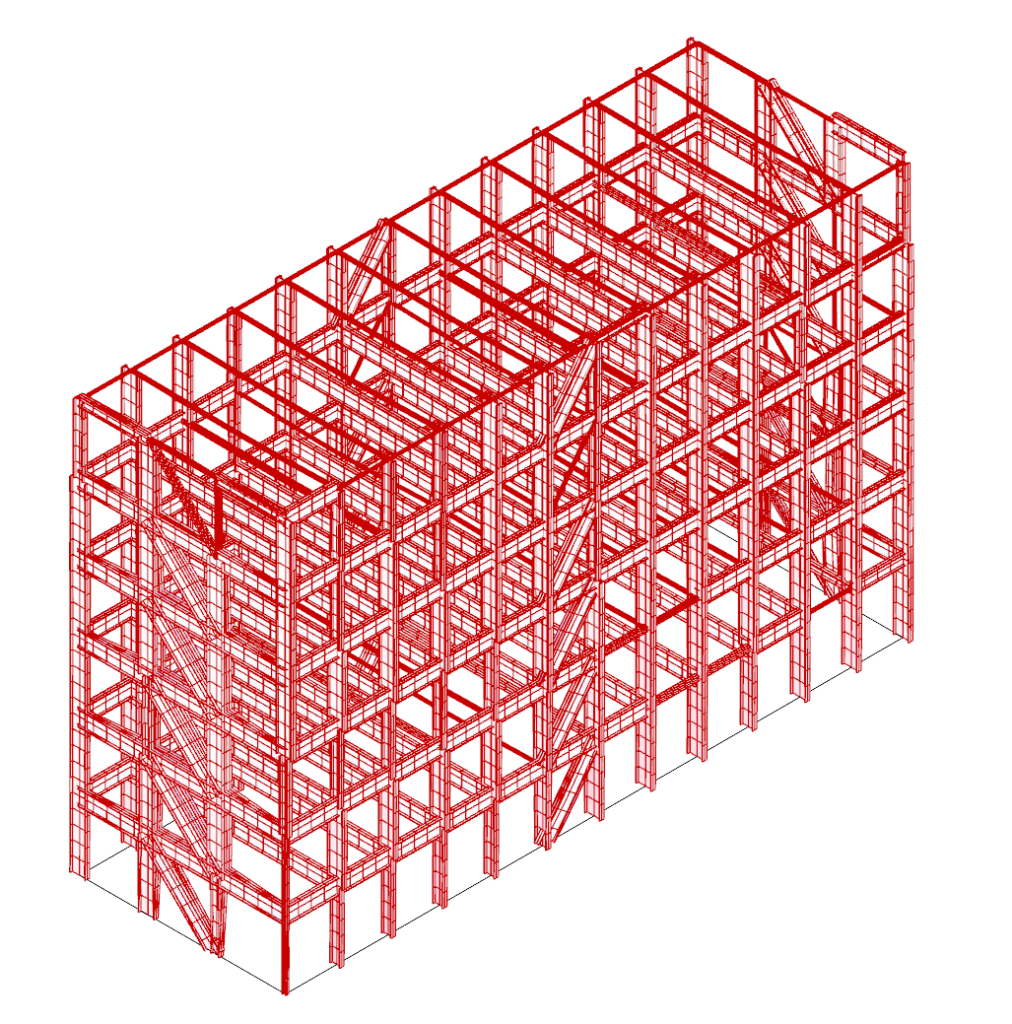
Results
Initial optimized cross section values:
# of structural elements: 336
# of structural nodes: 4174
CO2 footprint: 867,302 kg
After Opossum optimization:
# of structural elements: 306 -9%
# of structural nodes: 4196 +5%
CO2 footprint: 850,542 kg -2%
CO2 reduction: -16,760 kg

