
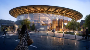
From historical times, dendriforms have been used as architectural inspiration earlier they were just used for bio replication ( i.e just for aesthetics ) but soon they were used as a prototype of biomimicry. Our study was based on one of such examples – the World of Volvo ( Image 1) where the biomechanics principles of minimizing energy expenditure have been used to minimize the path of load transfer, the principle of uniform energy utilization has been used to support a large photosynthetic surface by a narrow trunk and controlling the length of beams by branching and sub branching them so that the beams don’t fail in spanning long column-free spaces.
World of Volvo, Sweden – Prototype of Biomimicry
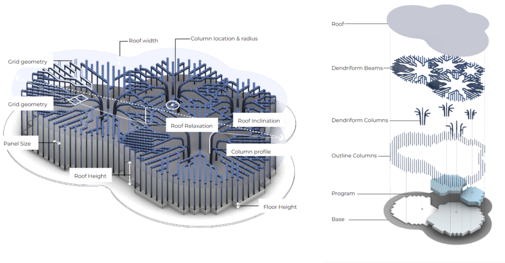
Structural principles inferred from World of Volvo are as seen below
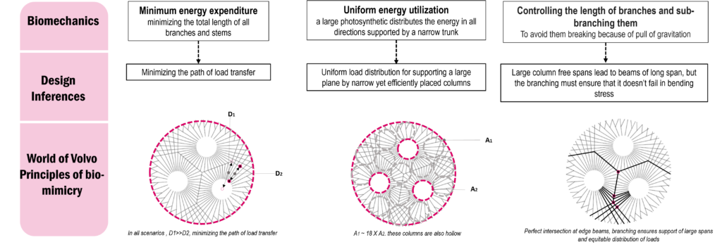
Inferences from this study
In the world of Volvo study, what could be inferred is that as it’s a circular plan, areas are divided equally, and though the radiuses of the column may vary they are equidistant from the center and that is how this principle can be extrapolated to any regular polygon to get those perfect intersections at the edge beams and at the façade.
When extrapolated, these principles can be used for any regular polygon-shaped roof plan to get those perfect intersections at the edge beams and the façade.

Pseudocode
Our aim was to extrapolate this concept for any base plan curve input from the designer to create dendriforms. Using the above narrative the parametrization strategy of the project was developed. The input from the designer could either be an input plan curve with different programmatic circles or a CSV file with detailed area programs.
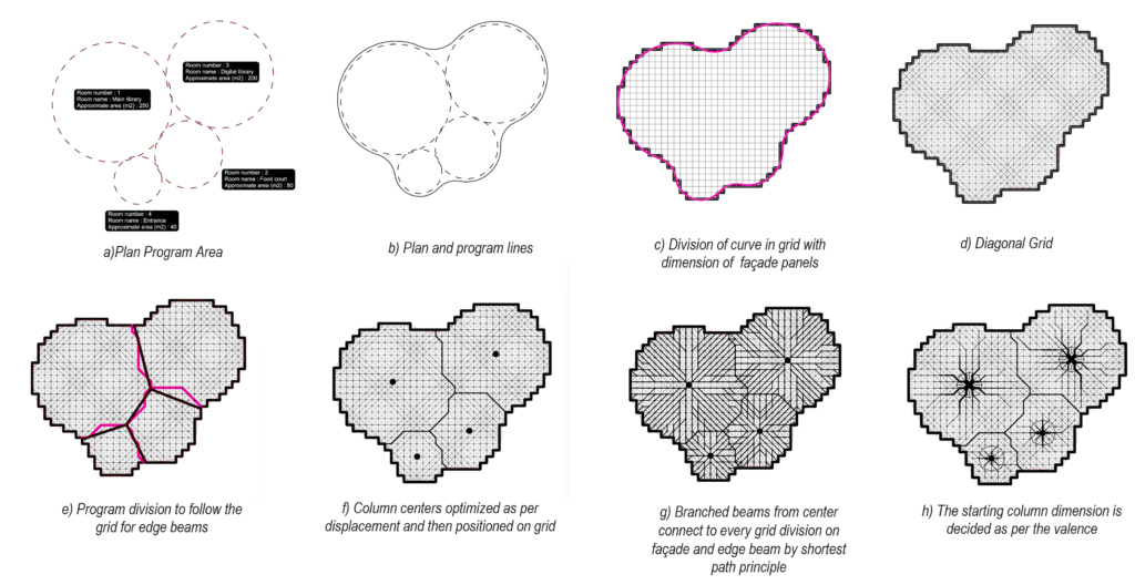
The beams meet at the edge curve and are projected downwards to get peripheral columns, giving rise to a cohesive system of beams and columns, where they are part of the same structural member rather than standalone members.
The script allows for the designer to control the following parameters as per their design intent:
- The division grid (square or hexagonal)
- Size of the column (which can later be optimized for reduction in displacement)
- The column positioning (which can later be optimized for reduction in displacement)
- The height of the different spaces
- The curvature of the beam and column intersection
- The roof slope direction and angle (can be based on environmental factors)
- The roof overhang (can be based on the amount of sunlight needed as well as snow to drain off the roof)
- Size of the column (which can later be optimized for reduction in displacement)
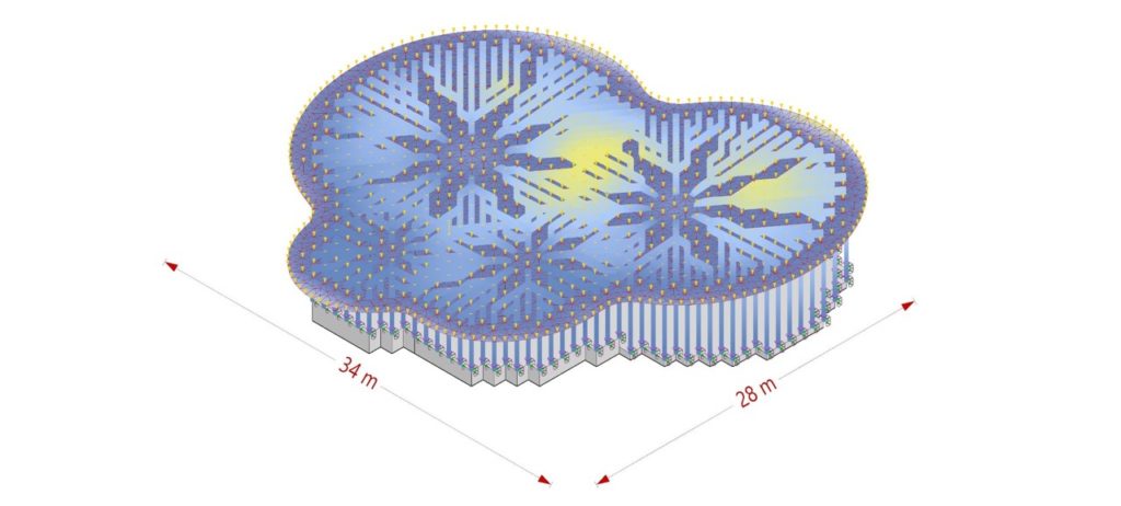
Structure Finite Element Model
Using Karamba3D, the geometry is realized structurally as shown below
The following loads were applied to the model to analyze the deflection and the buckling load factor of the design:
- Life load (0.5 kN/m2)
- Snow load (1.4 kN/m2)
- Wind loads (1.0 kPa pressure, 0.5 kPa suction)
Structural Optimization
For minimizing the displacement under the given loads, as well as increasing the buckling load factor above 1, Wallacei was used for structural optimization. The following video shows the different parameters that were optimized.
After the optimization of column placement and roof relaxation, the displacement is within limits, and the buckling load factor is 0.12. Therefore the structural cross-sections were optimized to get a buckling load factor to 4.71. This resulted mass of the structure being 35 568 kg.
The building resulted in a SCORS rating of C, with the embodied carbon at 156kgCO2e/m2.
Conclusion
With the input of any planar curve, a dendriform structure can be formed. However, this type of structure is not the most optimal in terms of structural performance. In our case, the mass of the building was very high, compared to other types of structures. However, the mass has been deliberately increased, to optimize the buckling factor and displacement. To decrease the mass without sacrificing the structural stability, additional elements should be added to stabilize the structure (such as column rings or additional internal columns at the intersections).
References
https://henninglarsen.com/en/projects/featured/1821-world-of-volvo
https://www.novatr.com/blog/world-of-volvo
https://www.bytbil.com/nyheter/forsta-bilderna-har-ar-world-of-volvo-25111
