00- ABSTRACT
Digital fabrication is a design and manufacturing workflow where digital data directly drives manufacturing equipment to form various part geometries. This data comes from CAD (computer-aided design), which is then transferred to CAM (computer-aided manufacturing) software. This data directs a specific additive and subtractive manufacturing tool, such as a 3D printer, CNC milling machine and Laser Printing. The aim of this exercise is to learn these digital fabrication production techniques and design strategies within the capabilities and limitation of material and machine.
01- 3D PRINTING
The aim of this exercise was to develop complex 3D printing components that will proliferate, and adjust CAM settings (in Z-Suite software) to optimise printing time, material usage and print quality.
The design is limited by a 1:1 Modul (155 x 165 mm) for a facade with Zortrax M200, 3D printer. Therefore, a total printing time of 10 hours was required.
For final Module, facade shading had to be taken into consideration.
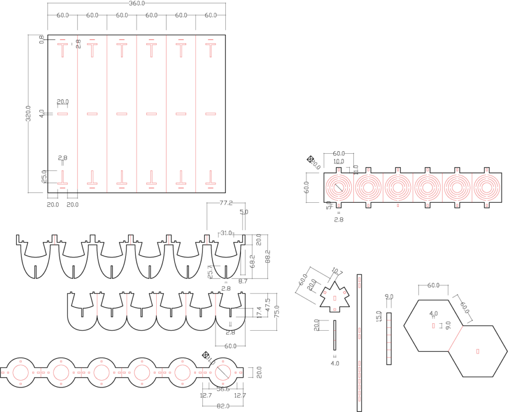
Prospective Geometry
Z- Suite settings:

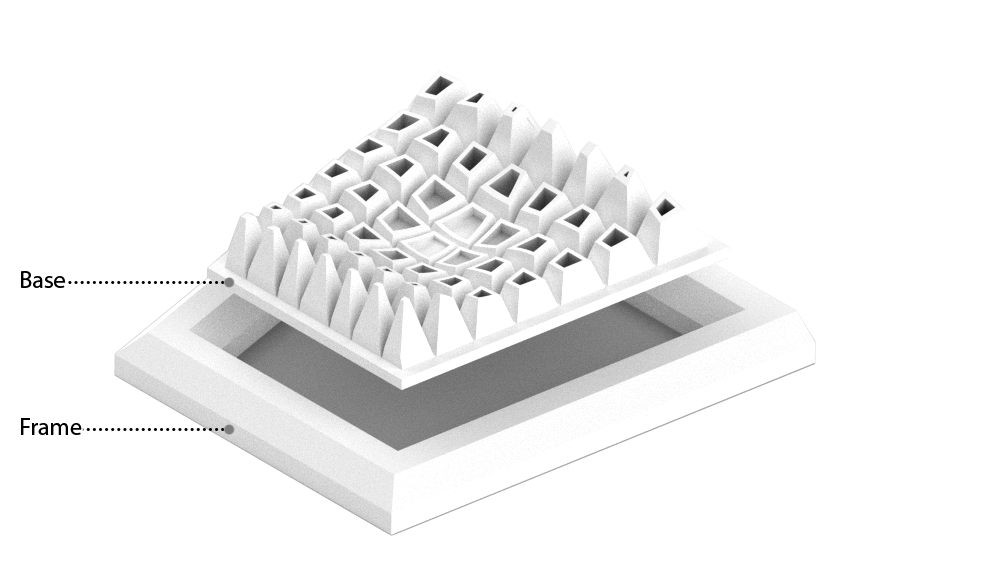
The base was given to connect to the wooden frame.
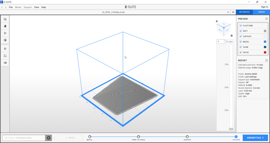
Give a base to prevent model move while printing.
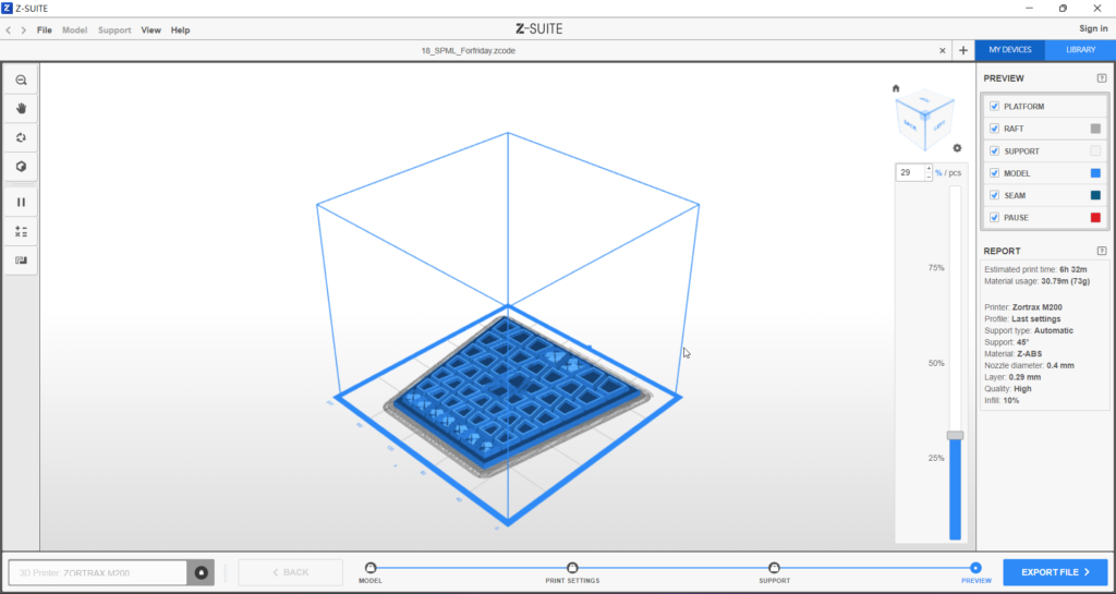
Change the density to reduce time.
Printer: Zortex M200
Profile: Last settings
Support type: Automatic
Support: 45
Material: Z- ABS
Nozzle Diameter: 0.4mm
Layer: 0.29mm
Quality: High
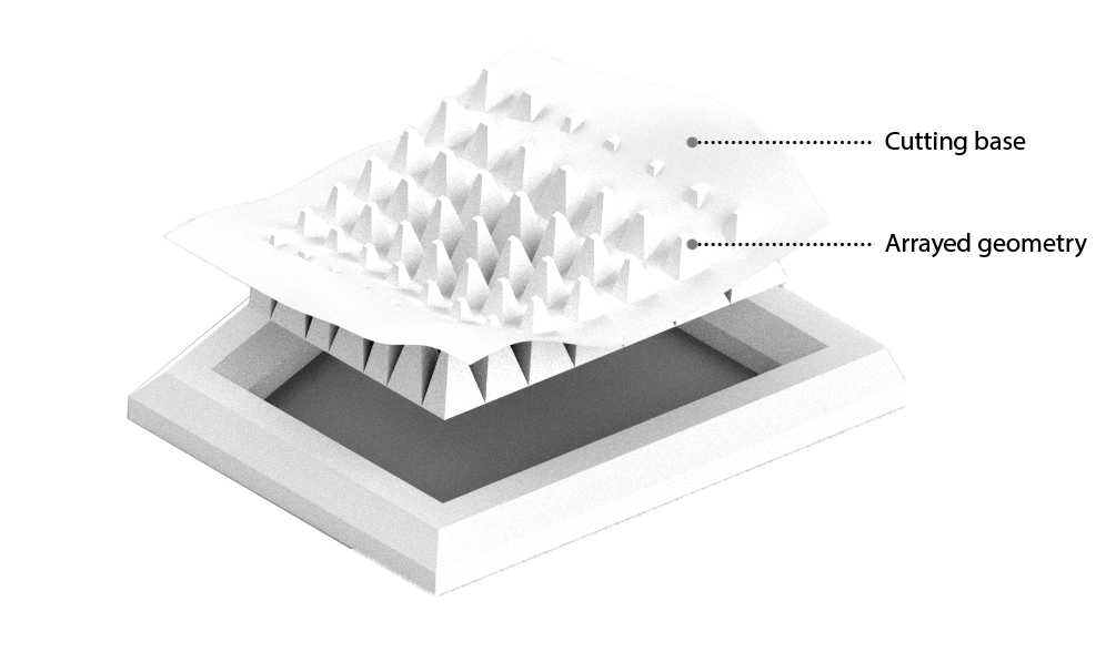
In model we make each pyramid to become a shell to have a aesthetic final outcome.
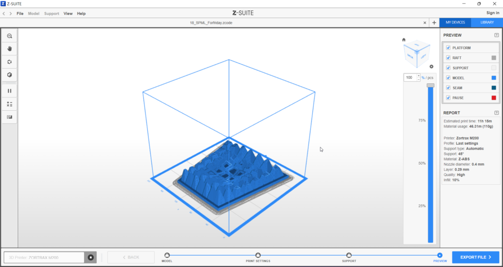
An overall dynamic shape to create shading.
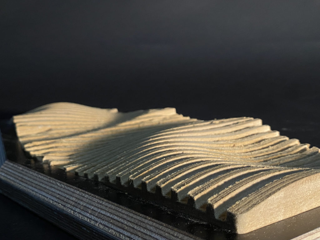
02- CNC MILLING
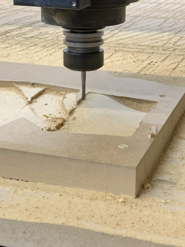
CNC machining is a subtractive manufacturing technology: parts are created by removing material from a solid block using a variety of cutting tools. It produces high-accuracy parts with excellent physical properties directly from a CAD file with a high level of automation.
2022/ 10/ 10- 10/ 17
Prospective Geometry
Positioning and fixing the MDF slab by positioning screw.
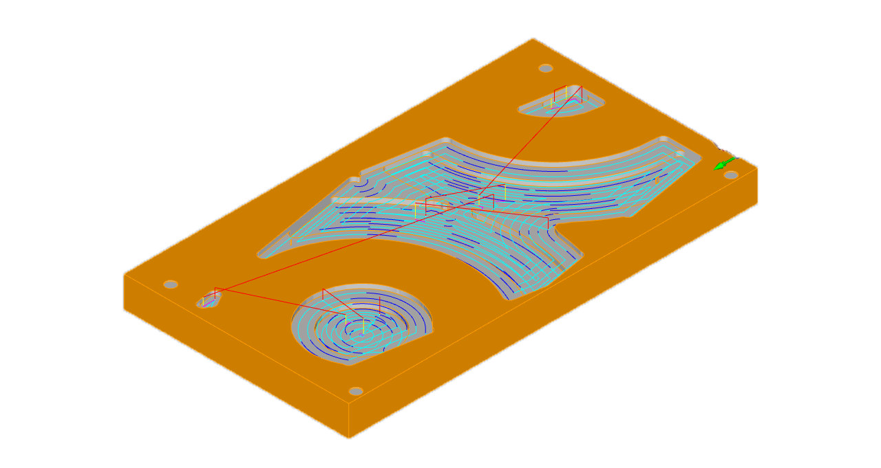
Flat Mill
Flute: 30mm
Diameter: 10mm
Spindle Speed: 12000 rpm
Cut Direction: Downcut
Step Down Control (dZ): 60%
Stepover Distance: 70%
Total mill time: 4.13 min
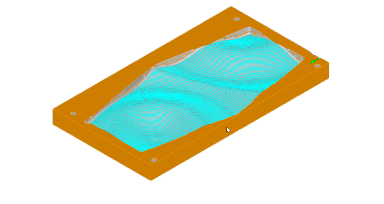
Ball Mill
Diameter: 6mm
Spindle Speed: 12000 rpm
Cut Direction: Mixed
Stepover Control: 20%
Total mill time: 22.81 minutes

Flat Mill
Diameter: 6mm
Spindle Speed: 12000 rpm
Cut Direction: Upcut
Total mill time: 4.97 minutes
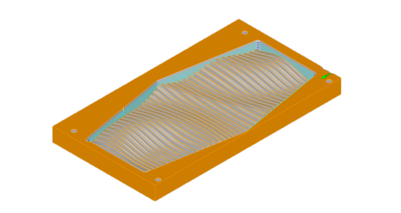
Flat Mill
Diameter: 6mm
Spindle Speed: 12000 rpm
Cut Direction: Upcut
Depth Control :Total cut depth 5mm
Rough cut: 1mm
Finish depth 4mm
Total mill time: 10.31 minutes

02- CNC MILLING
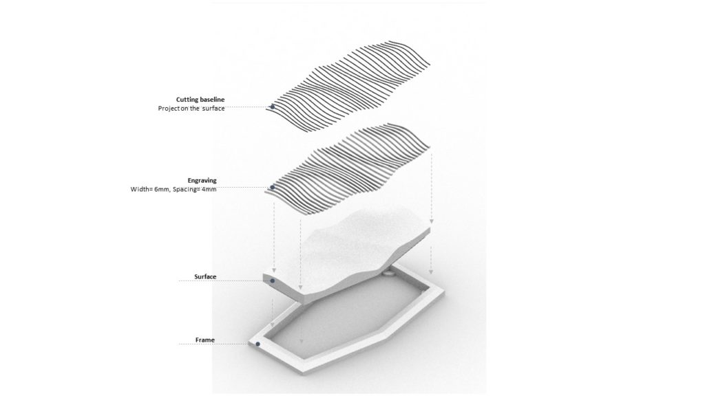
LASER CUTTING
2022/ 10/ 17- 10/ 24
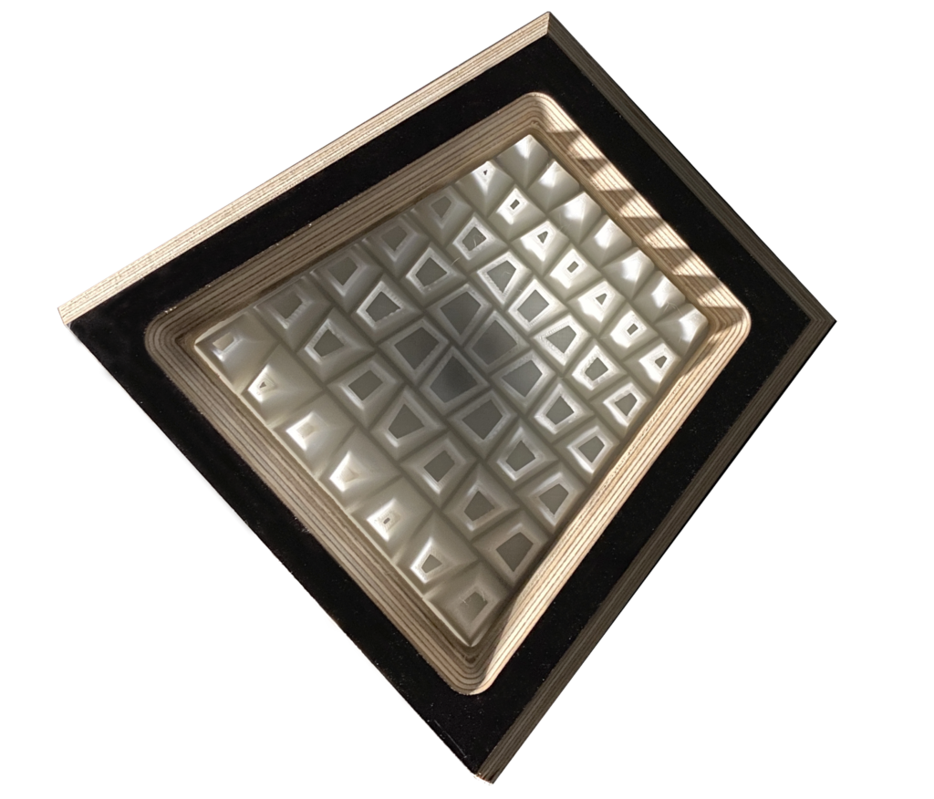
Final structure render