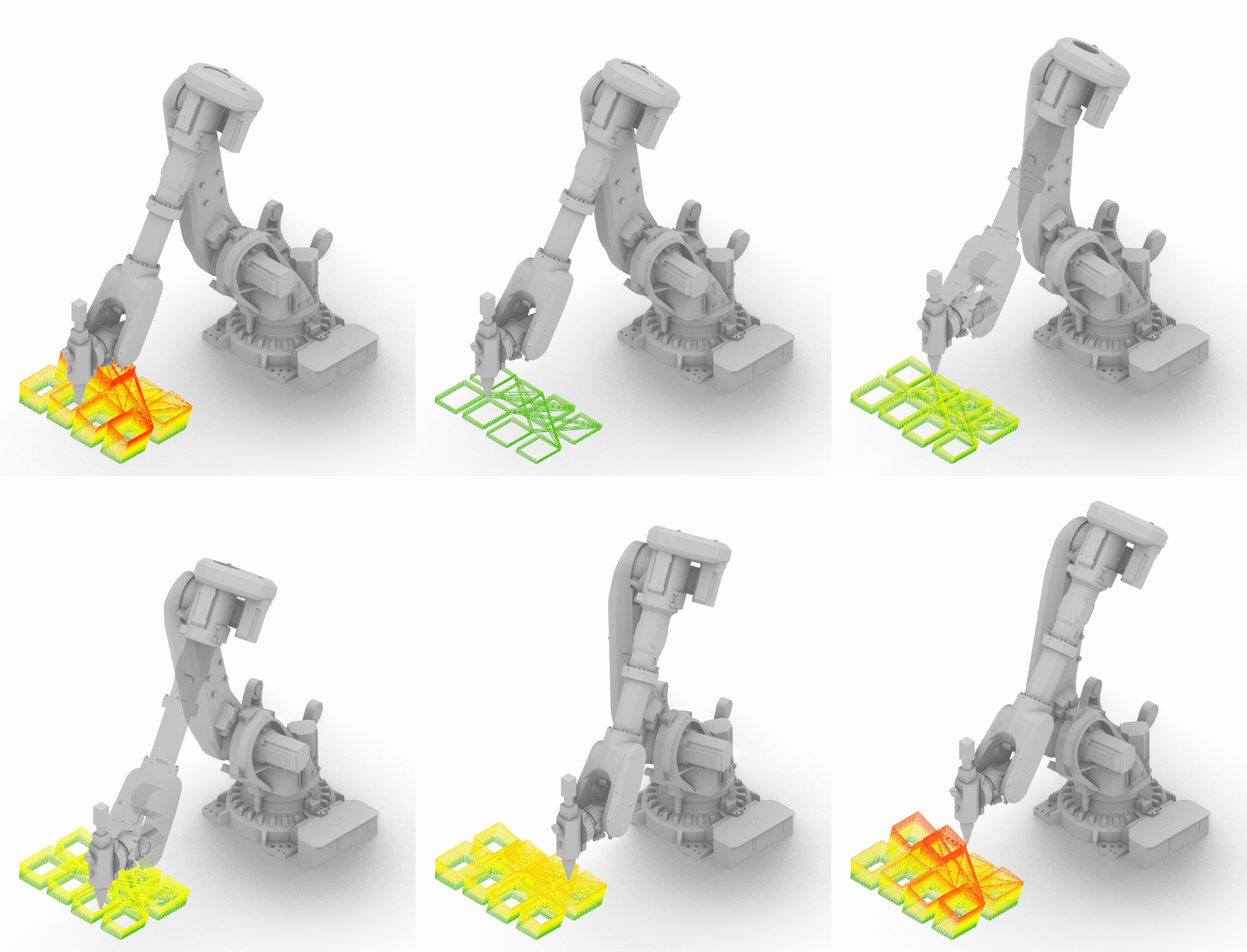
The Software-I seminar introduces computational design strategies for robotic fabrication, focusing on the software aspects of these processes. The following exercises cover different manufacturing strategies that translate digital models into buildable forms through precise toolpath development and simulation. These include an end-to-end process from conceptual design to the generation of fabrication files for robotic systems, using Rhino and Grasshopper for geometry processing, toolpath development, and process simulation.
Design for Manufacturing of Interior Design Systems Enabled by Advanced Robotic Milling
This exercise comprises a substractive fabrication strategy for a robotic milled complex interior design system, ensuring it is buildable and manufacturable.
1. Interior design system
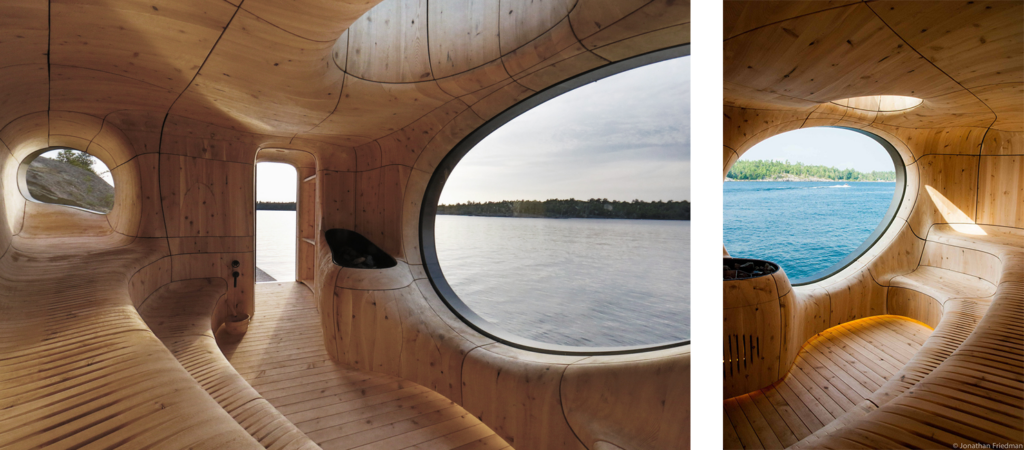
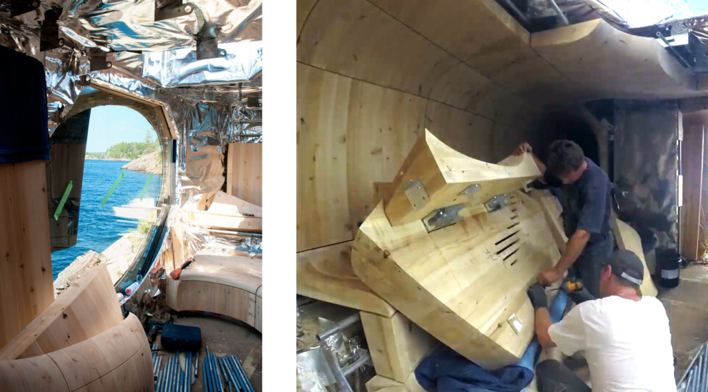
The chosen system is Grotto Sauna by Partisans. This sauna has an interior panelling of solid cedar wood blocks. These blocks have a visible face with an organic double-curvature surface, while the hidden sides are flat or single-curvature faces.
2. Segmentation strategy
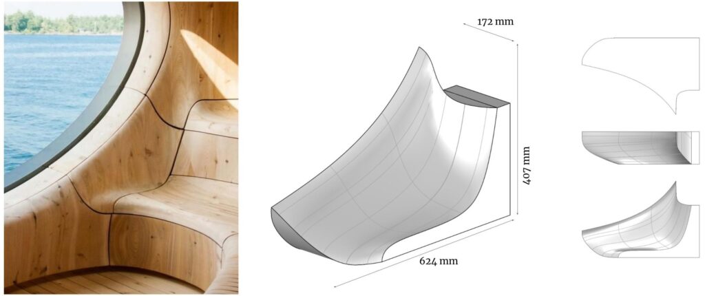
For this case study the following module is chosen:
3. Stock material optimization
To obtain the desired piece, it is needed a roughing milling and a finishing milling. This last strategy is the one covered in the following explanations.

4. Material & tool setup
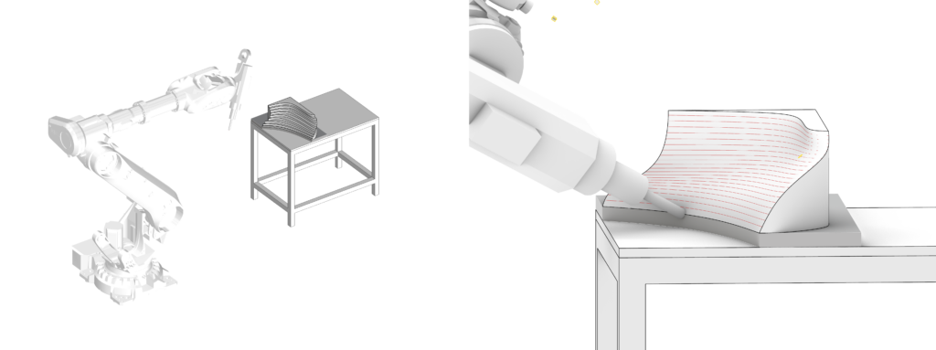
The stock is placed within the robot reaching area, elelevated on a base in order to not hitting the supporting table when milling the lowest parts of the stock.
The robot selected for this operation is a ABB IRB 6700-150/3.20 with a 20mm flat-end mill.
5. Toolpath strategy & approaches
On the milling face, we divide the longest transversal line into the step-over distance (75% of the 20mm tool diameter = 15mm) in order to obtain a single back-and-forth longitudinal toolpath for the milling toolpath.
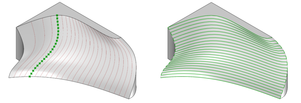
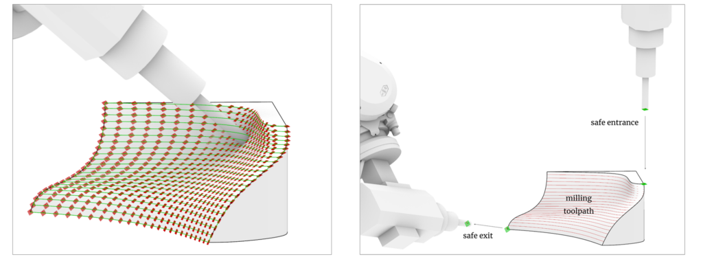
A 5DOF toolpath is chosen for this milling strategy, as it can obtain a good finish with a flat-end mill and it takes fewer passes than a 3DOF strategy, which would need more passes and a rounded tool in order to obtain similar finishes. However a post-milling sanding will probably be needed to smooth the surface. Some of the most concave parts of the piece might result in a bad finish with the selected tool. In this case one option could be changing the tool for a smaller diameter, or changing to a ball-nose mill.
- Feed Rate 3000 mm/min = 50 mm/s
- Spindle 10,000 RPM
6. Errors & warnings
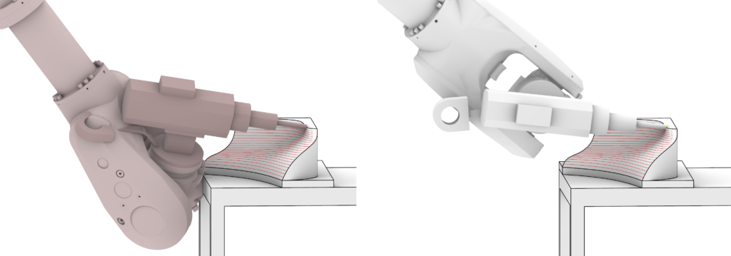
Changing the TCP orientation planes can avoid errors with the axes of the robot.
7. Simulation
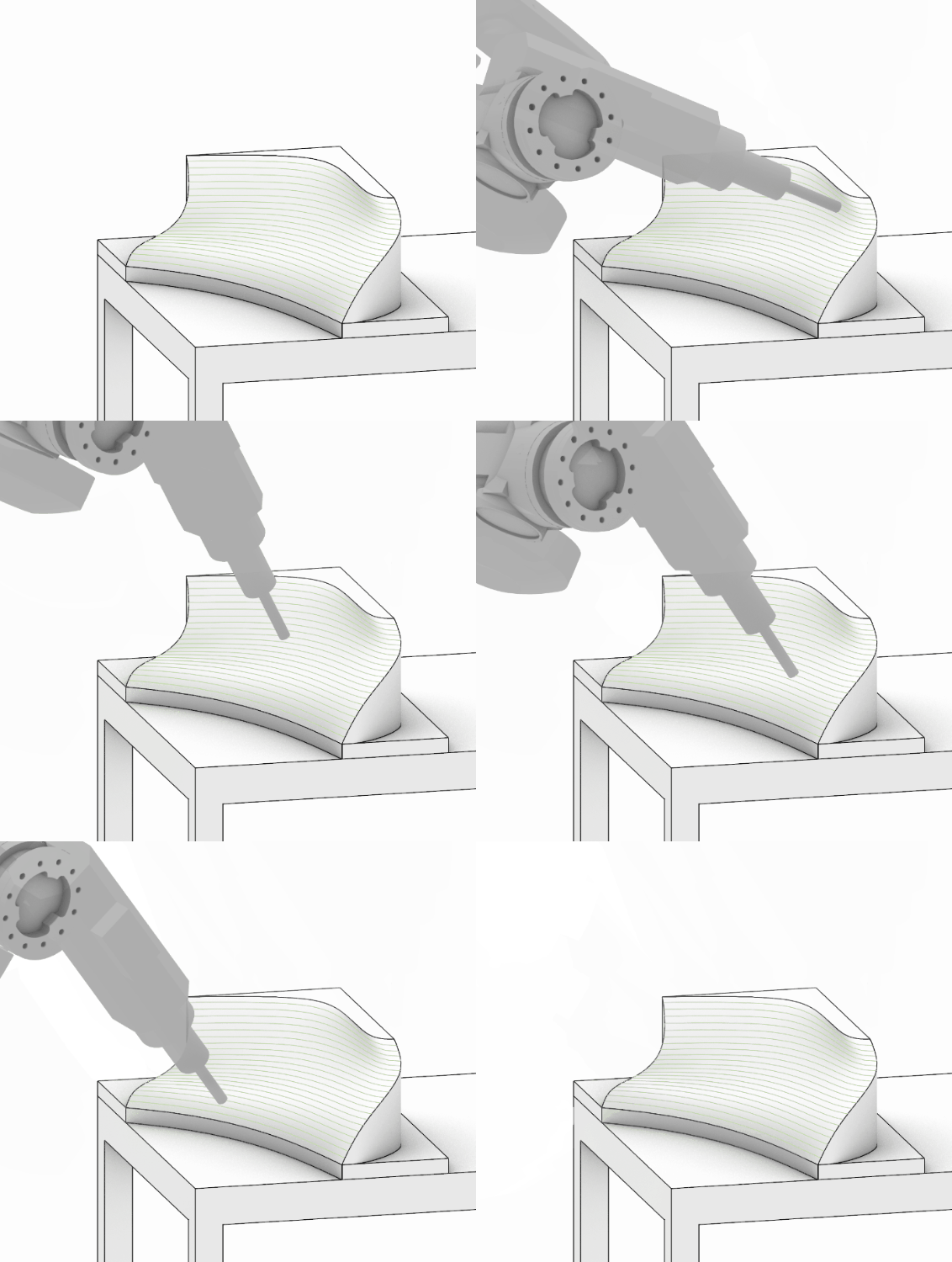
8. Feasibility analysis
To manufacture the visible face of the selected module (0,15m²) it takes around 5 min of finishing milling with a block of solid wood of 0,05m³.
For the whole system of modules, it is estimated a total of 80m² of milling surface, with around 45h of finishing milling time and a total of 18m³ of material.
However, this is just an estimation based on the selected module which might be too small to be representative of the whole system, to do a proper calculation, the 3d model of the whole system would be needed.

Some of the constrainsts to consider when dividing the system into modules are the size and thickness of the pieces, which need to be in accordance to the size of the available cedar wood. Also for the tool to be able to correctly mill the entire wood thickness, a longer tool might be needed.
Design for Manufacturing of 3D Printed Architectural Systems
During this Exercise we observed how the integration of additive manufacturing (LFAM), with computational design methods holds promise for the Architecture, Engineering, and Construction (AEC) sector in order to promote a more sustainable development of our built environment. Based on a provided list of reference projects, the design of a 3D-printed complex architectural system for fabrication will be engineered. The task involves subdividing the chosen design into smaller modules or components, ensuring its buildability and manufacturability. The goal of the project was to evaluate the predefined structures, design an infill for clay 3D printing and create a toolpath for the robot.
1. Segmentation strategy

2. infills

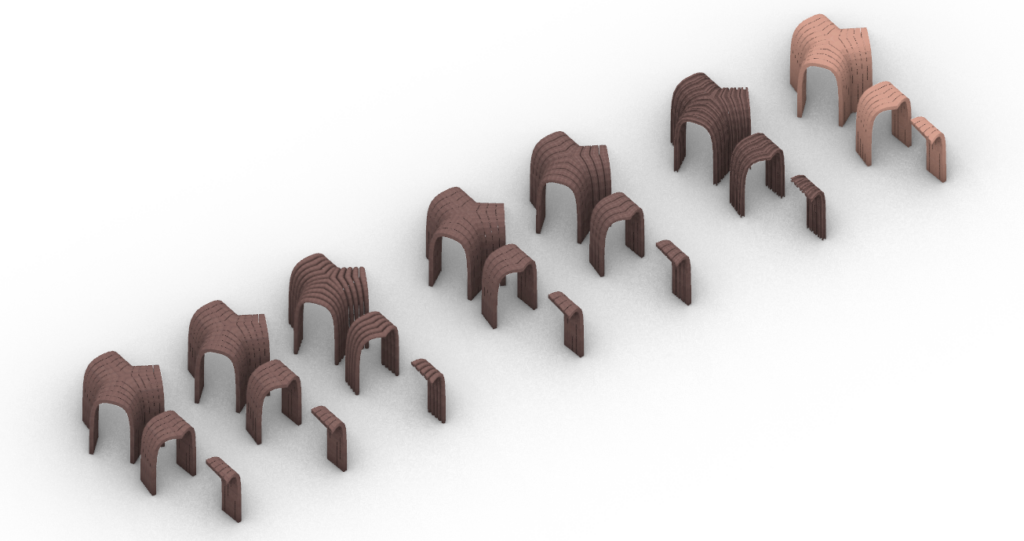
3. components
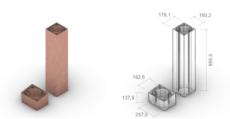
4. analysis
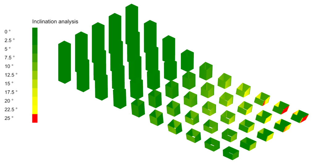
5. simulation
