
Designing Adaptive Framing System for
Warped Wood:
Exploring in to framing system that
accommodates different warped pieces of planks caused by uneven anisotropic bending characteristics of Pine Wood for
functional applications in architectural design and construction.
How can we create a Adaptable Frame System that accommodates different warped wooden pieces resulting from uneven anisotropic drying behavior of pine wood?
How can we incorporate this elements into architectural Design Elements ?
The natural warping of wood due to its anisotropic behavior is considered as a defect in construction, leading to material waste.
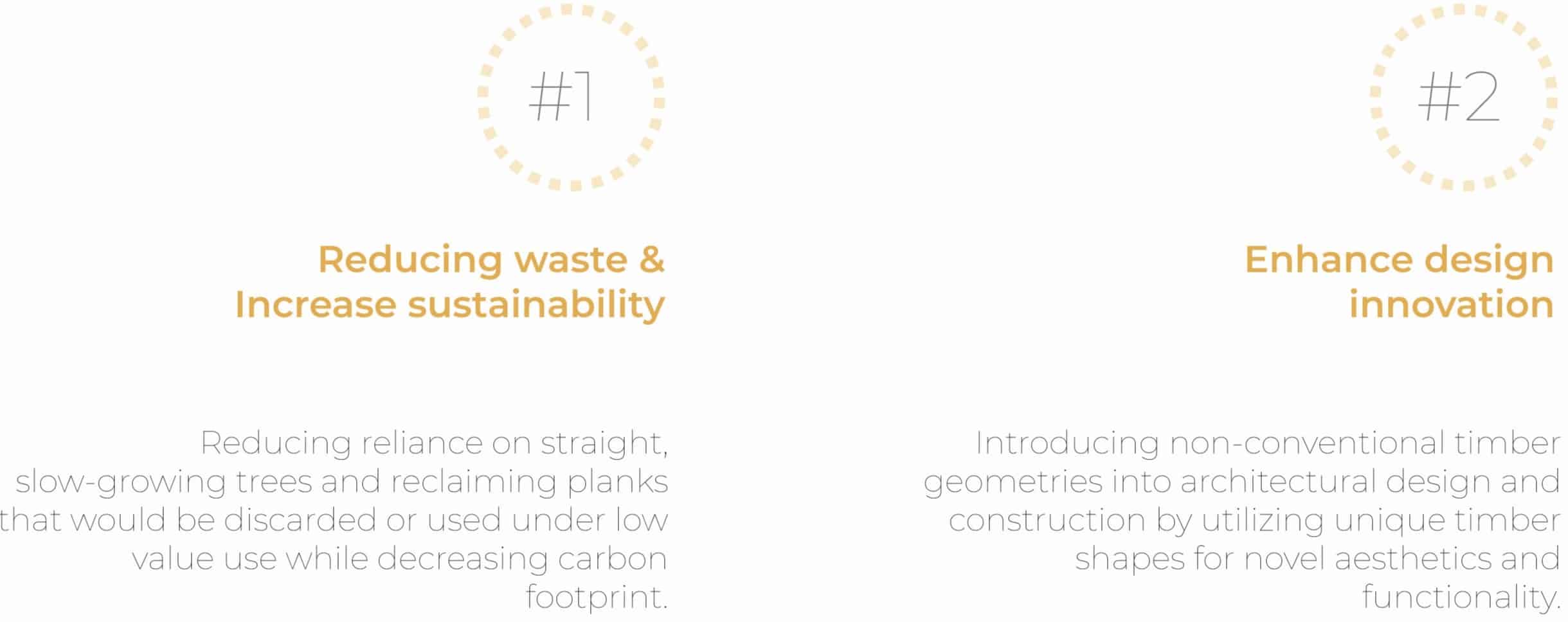
Constraining and correcting warped pieces rather than harnessing its behavior as a functional and aesthetic design driver are the current methods of solving this problem. Rather than fighting this natural behavior we can easily harness it for functional and aesthetic benefits.
Standardizing adaptive frame that accommodate different warping types allowing wood to be used while reducing wood waste and energy consumption.
Wood Waste in Europe (k Ton)
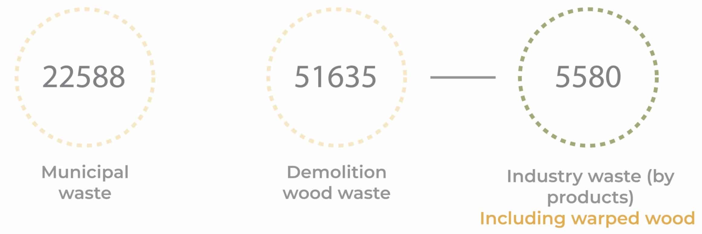
According to a local source working at Boix which is a wood manufacturing company based in Puig-reig,Barcelona, Catalonia, Mr. Josep Ferrer Garrig stated that

‘’2-3% of wood waste in Boix account for all the rejected boards, not only for
deformation but also for higher humidity or other defects.
Roughly the total reject (without the numerical control)
represents around 17%, out of approximately 24.000 m3 of
yearly volume.
Making total value of reject wood 2% of this value
480m3/year (Theoretical value).
No data has been recorded on how much deformed wood comes out of the drier.
Research Aim
This research provides a way of standardizing warped wood by creating a frame system that accept a certain dimensional range of warped wood planks in to architectural projects to reduce wood waste.
Anisotropic Property
(During drying process)
Wood is anisotropic, meaning its properties vary depending on direction longitudinal, radial, and tangential. This leads to dimensional changes and natural warping as the moisture content shifts.

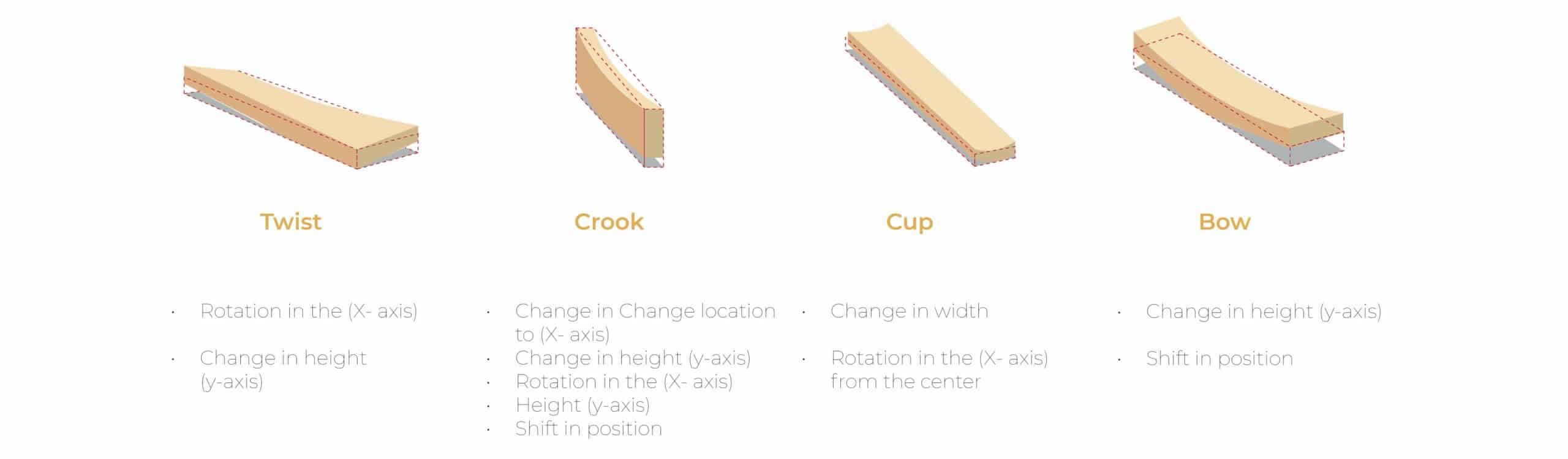
Types of Warping
Wood is graded based on visual or mechanical properties. Grading standards often eliminate warped or twisted boards from structural use, contributing to material waste. Wood warping is a deviation from flatness in timber as a result of internal residual stress caused by uneven shrinkage.
Plank Deformation
Grading standards often eliminate warped or twisted boards from processing, contributing to material waste by the use of sensors. According to Mr. Josep Ferrer Garriga, based on 2 providers that produce sensors: Micro tech & Weinig: planks with in this range are considered warped.
Note: planks over this limits scanner performances are not guarantee

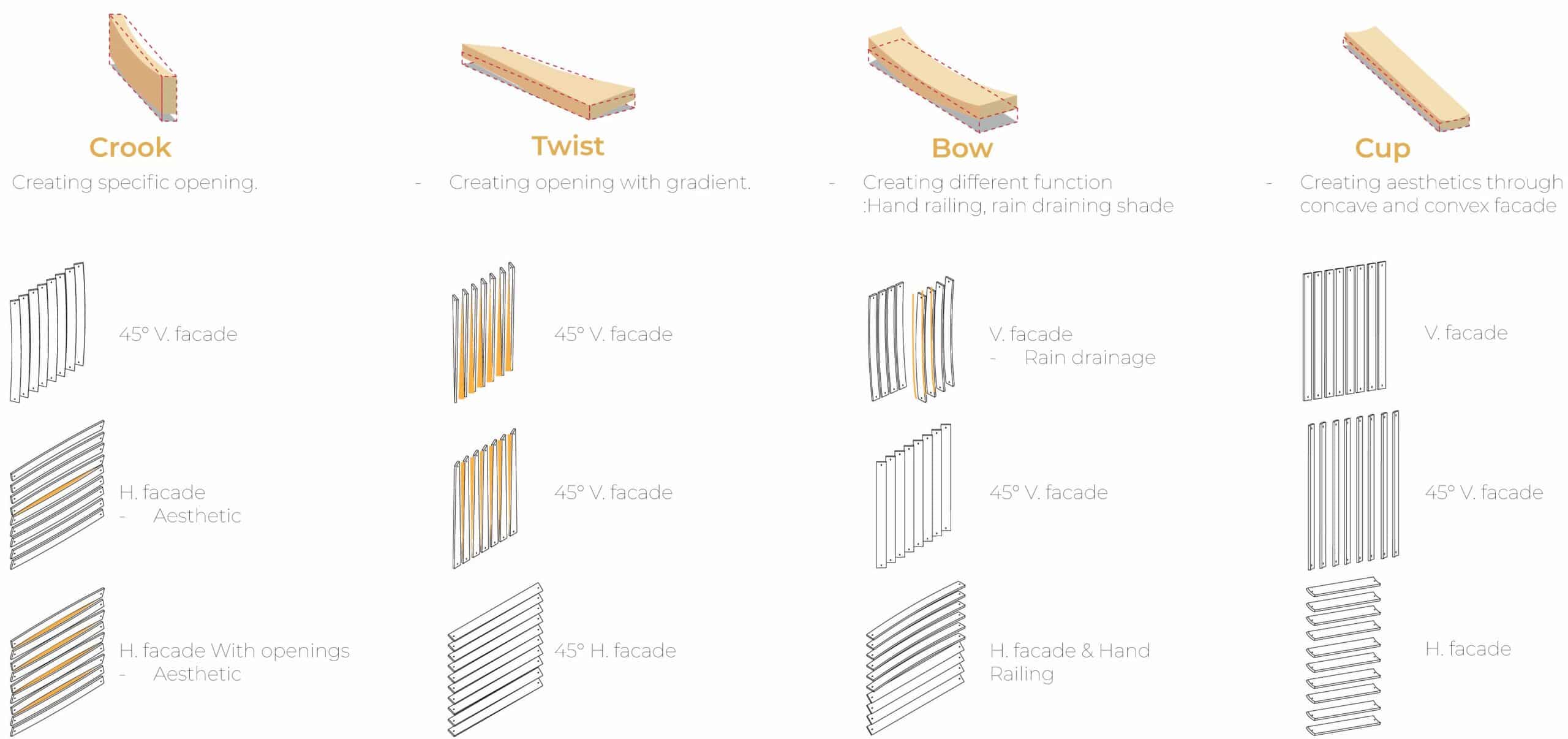
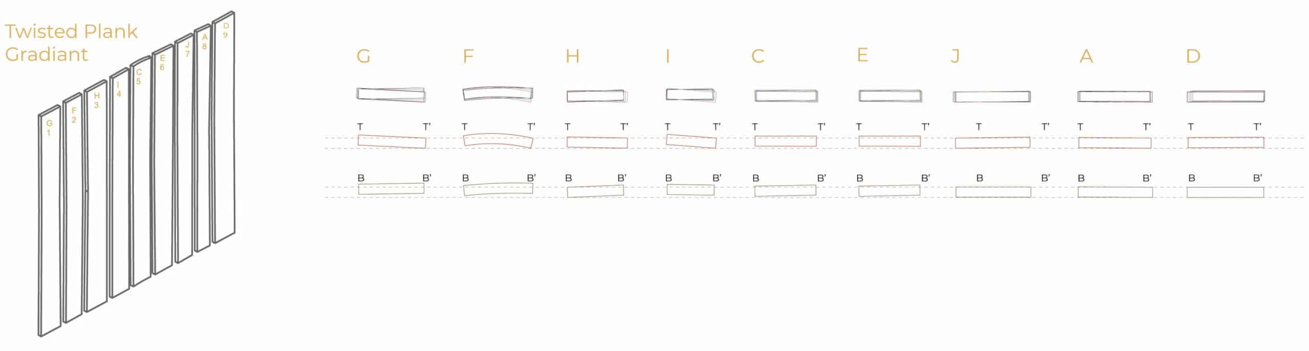
Potential Identification
(Same warpage)
Each warping type presents unique geometric characteristics that could be strategically utilized in architectural design. Crook and bow planks, can be used for flowing surfaces or convex façade elements. Twist warps, could function as a shading systems. Cup warps, can be ideal for rain shedding, cladding or acoustic paneling. By categorizing these deformation types, designers can match specific warp behaviors to functional architectural roles, turning former waste into material assets.
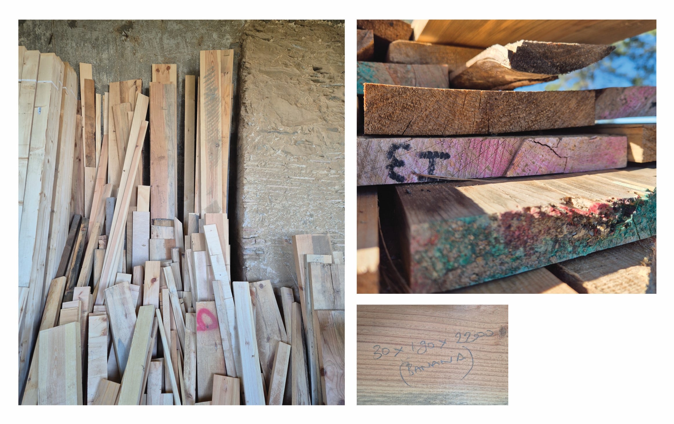
Warped Wood
(Experience, 2024/25)
Valldaura Labs During the Construction of the Cora , 2023/24 MAEBB 01 final project, planks where processed for making CLT panels. This planks warped due to drying in open air(uncontrolled environment) and were exposed to temperature change after being processed. This pieces were marked as trash (Banana) which was then stored separately to be reused after secondary plaining to avoid the curvature
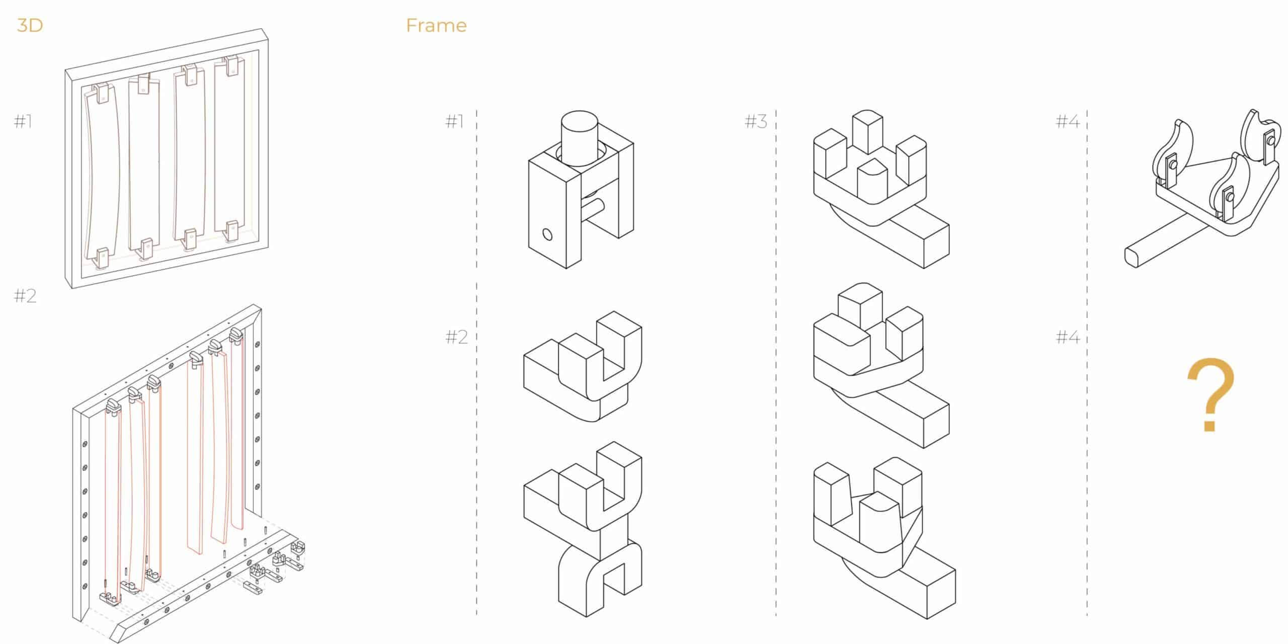
Design Exploration
The development of the framing system was driven by the goal of creating a modular solution that could accommodate the unpredictable variations found in the warped wood to a curtain level. The framing concept began with a U-shaped holder using dowels, but this approach caused cracking in the planks and introduced structural instability due to multiple moving parts. A second iteration tested a rotating 45° frame tailored to specific warp types, which improved adaptability but added mechanical complexity that conflicted with the project’s goals. The final and most effective solution used a three-point clamping system within a triangular hexagon frame, offering structural stability, simplicity, and modularity while accommodating various warp deformations.
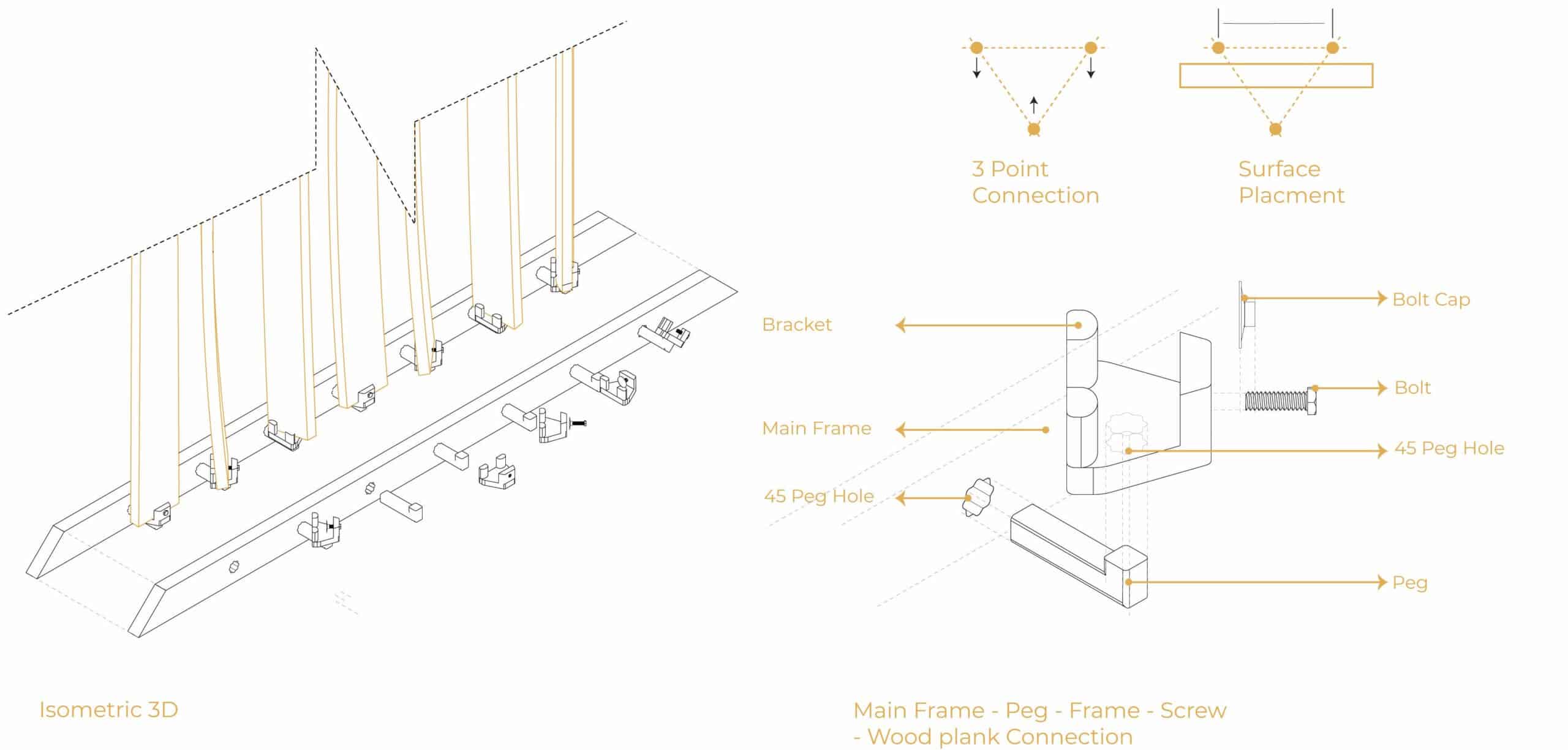
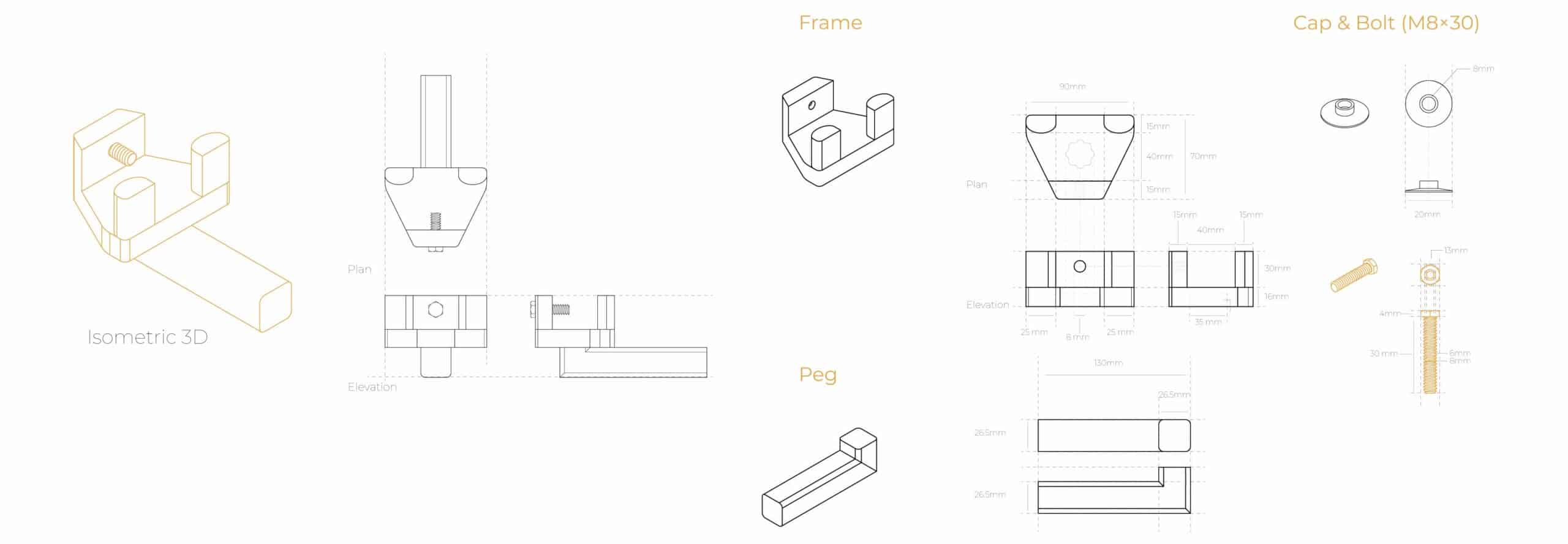
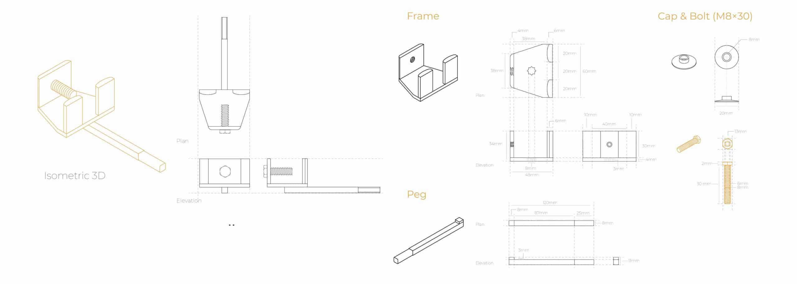
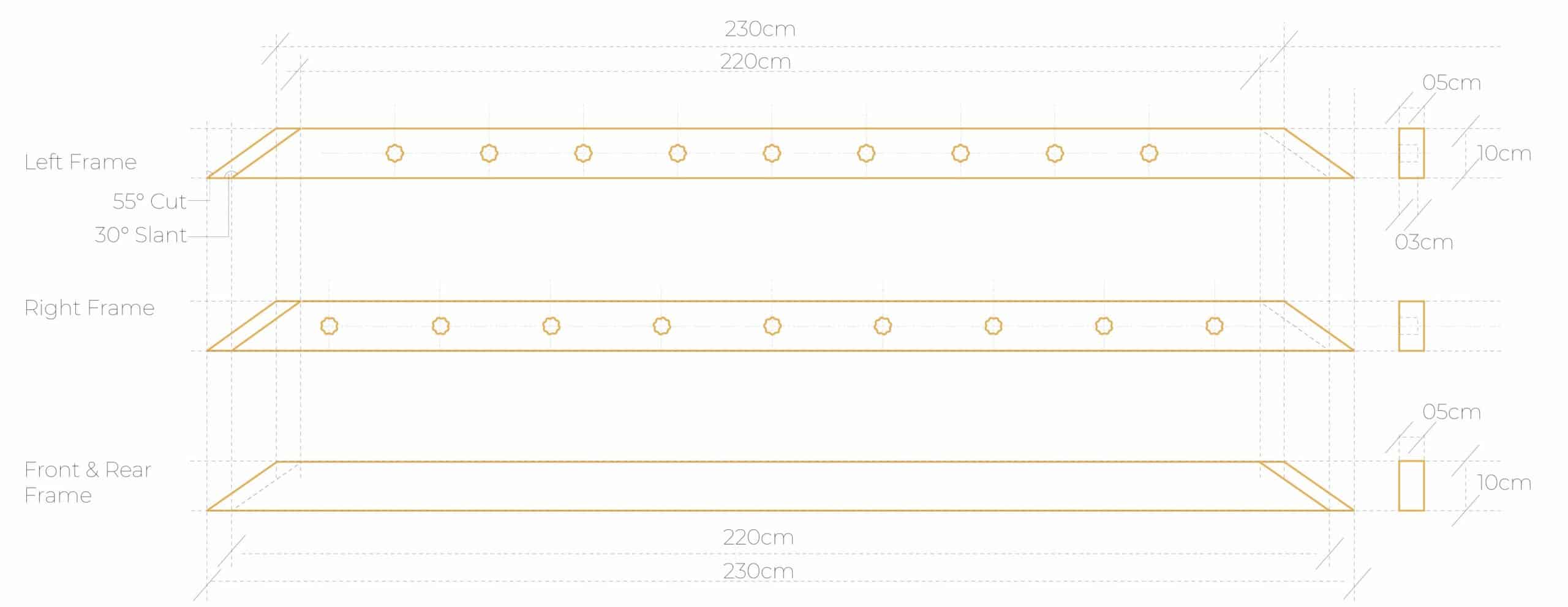
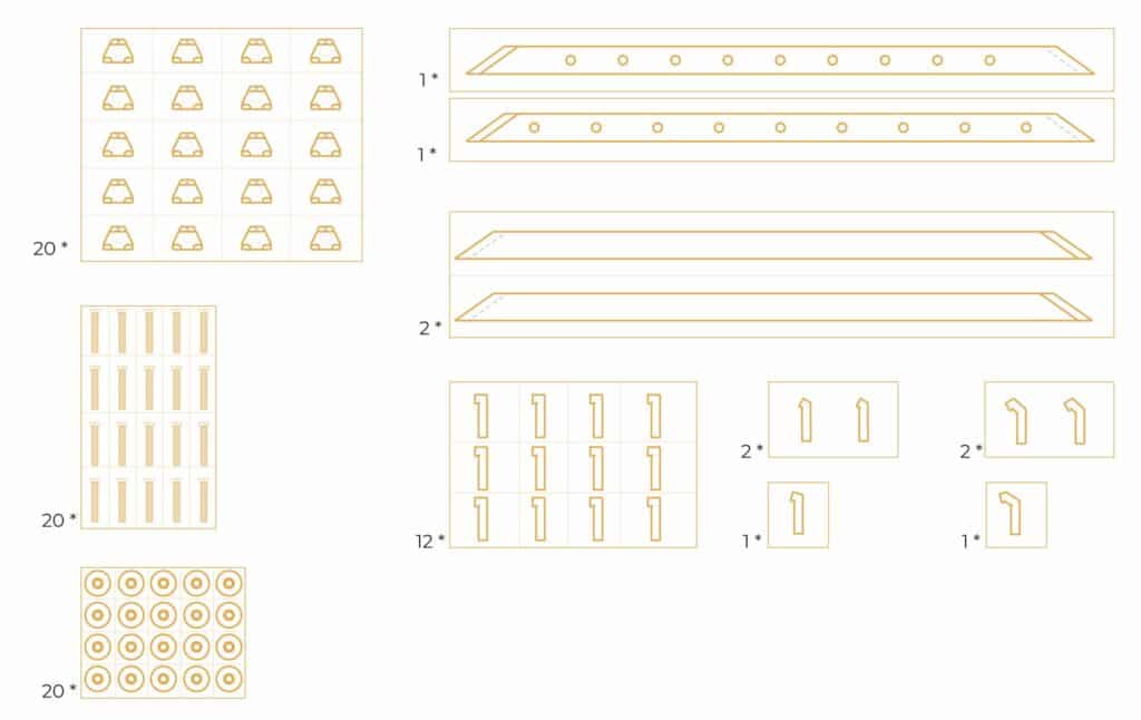
Final Frame Design
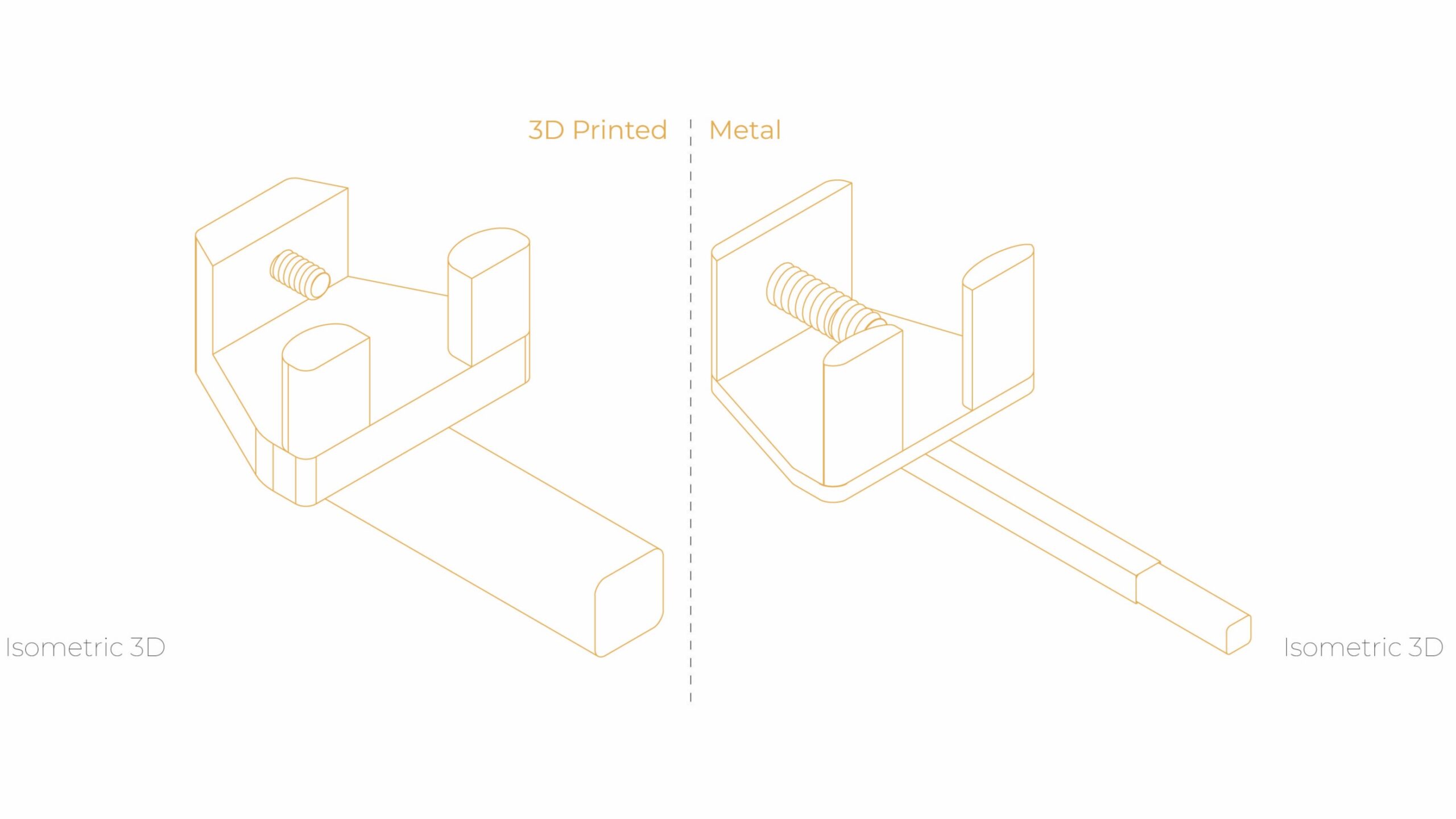
Frame Connection Mechanism
Frame Dimension
(3D Printed & Metal)
Available Resource & Selection
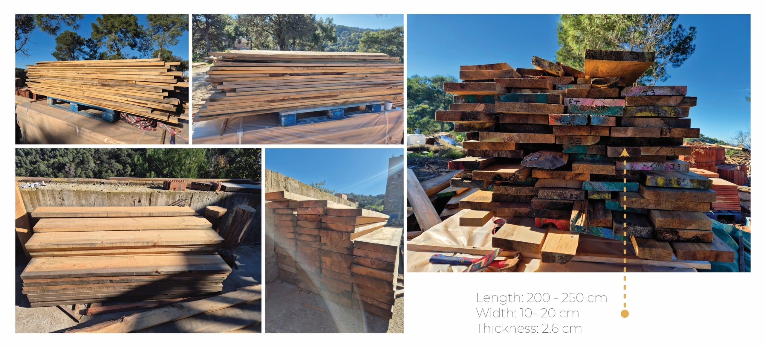
Material Library
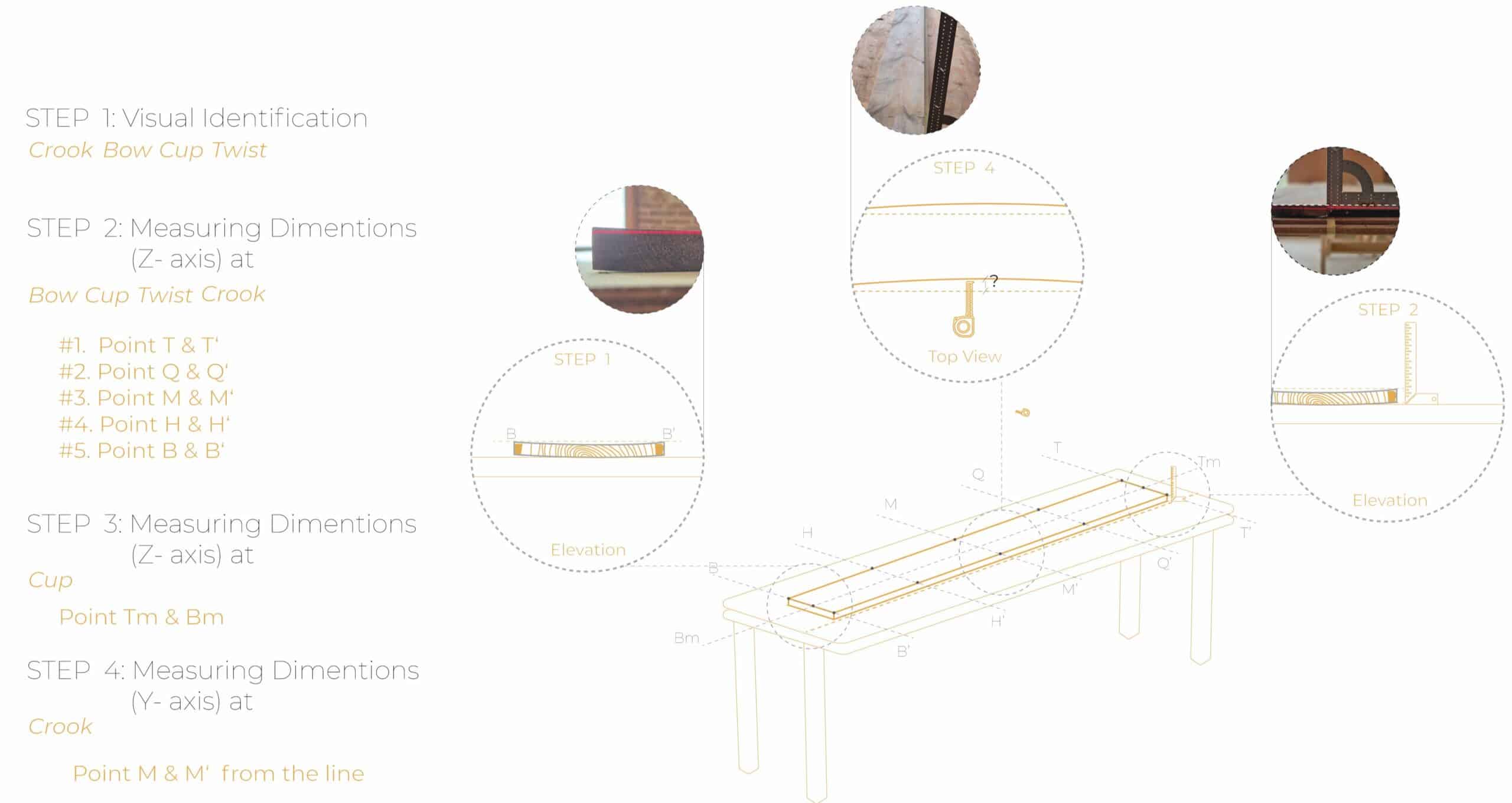
Warping Identification, Measuring Steps & Techniques
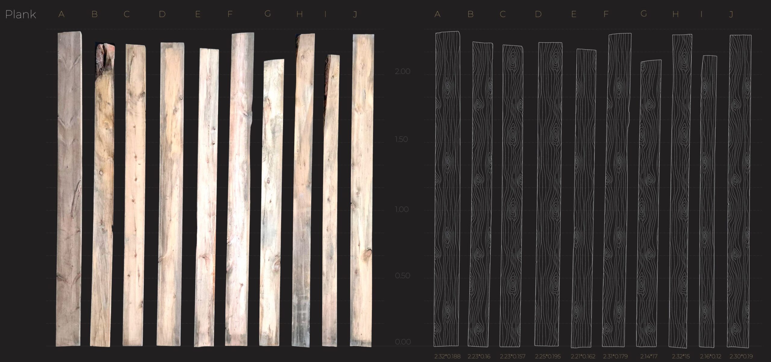
Measuring methods are employed to gather measurements of each plank’s physically. This includes length, width, thickness, and the degree of warp along different axes. The collected data from both photograph and manual measurements are later cross checked to ensure accuracy. These measurements are used to optimize frame geometries and allocate the warped pieces to a specific spot.
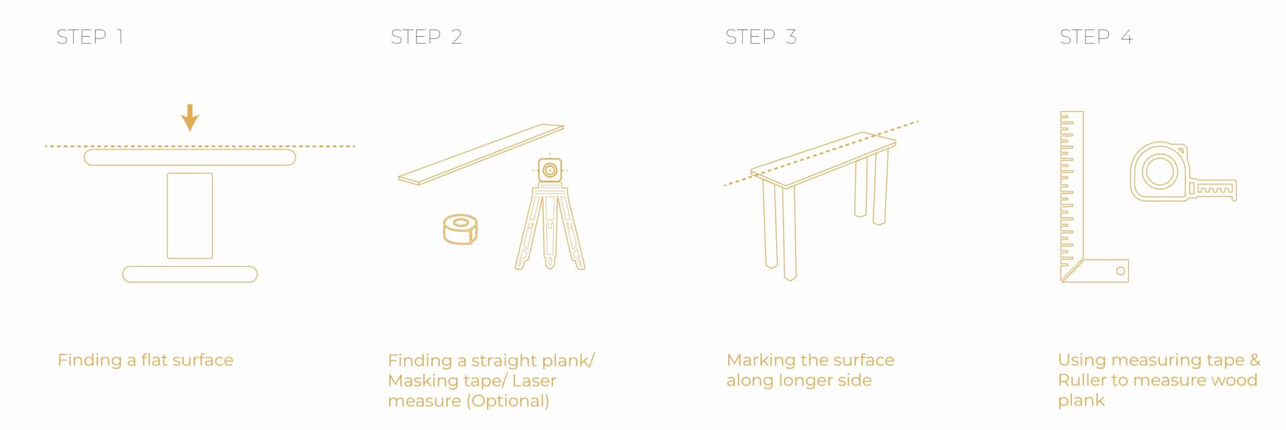
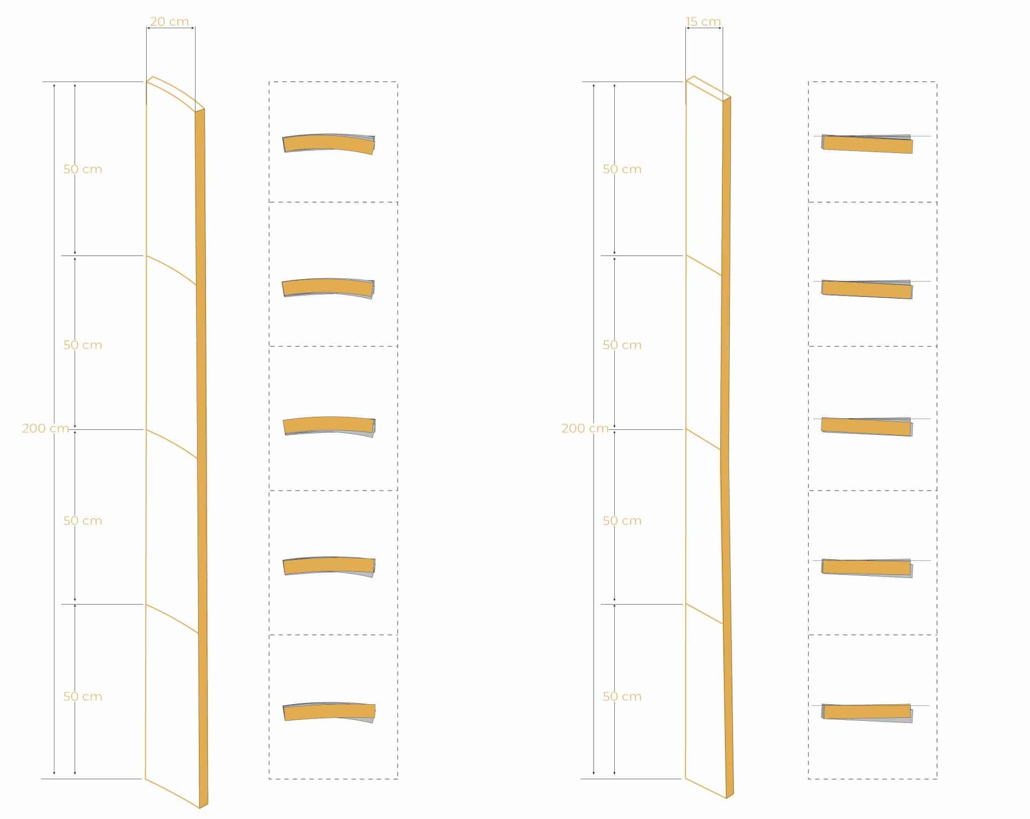
In order to get the dimension of the deflection, measuring at five different section of the planks is necessary. Identifying the warpage location in order to determine the type is necessary and on how much deflection it has, making sure it fails above the number determined by the sensor.

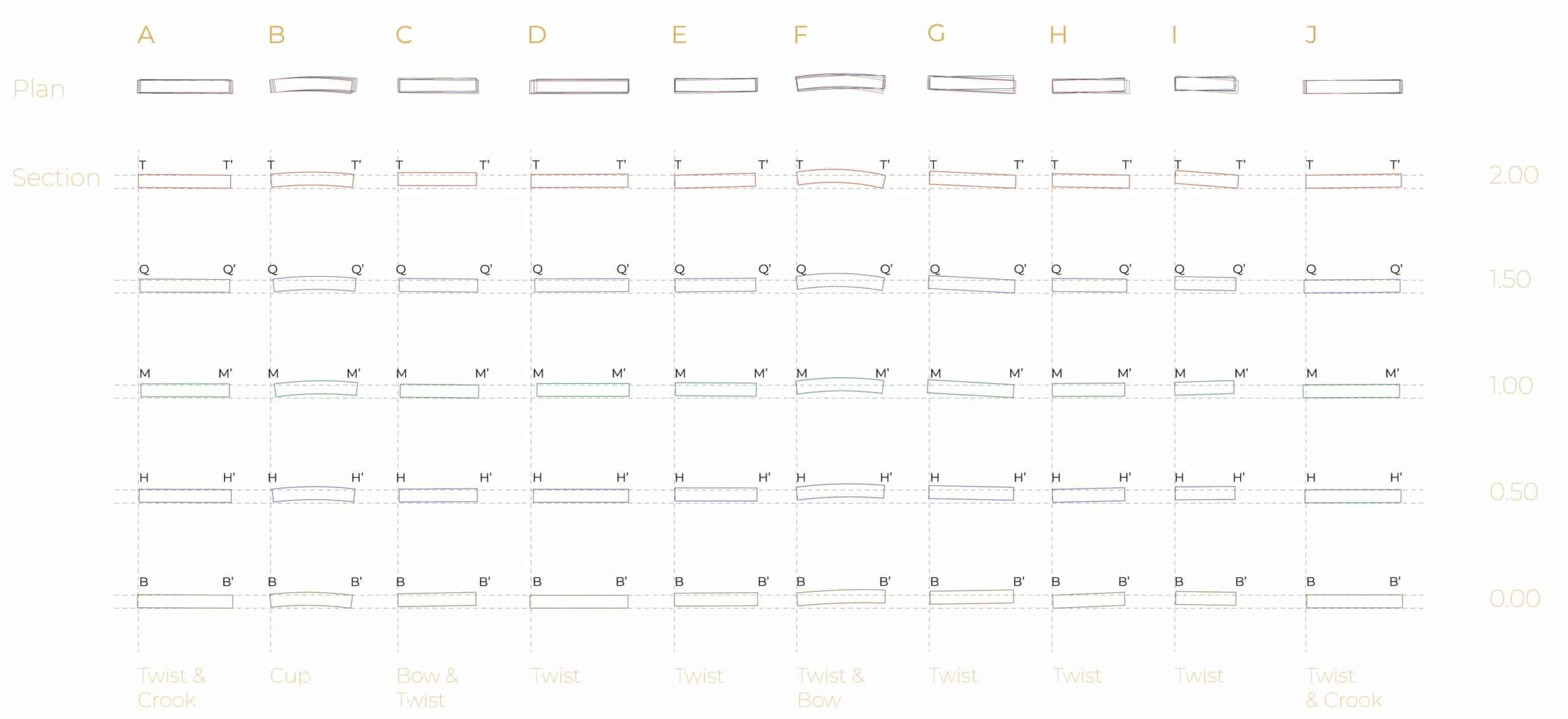
Plank Cross Section
Once all the data is collected, it is organized into a digital catalogue that serves as a comprehensive material database. Each plank is assigned an ID and categorized according to its deformation.
Material Catalogue
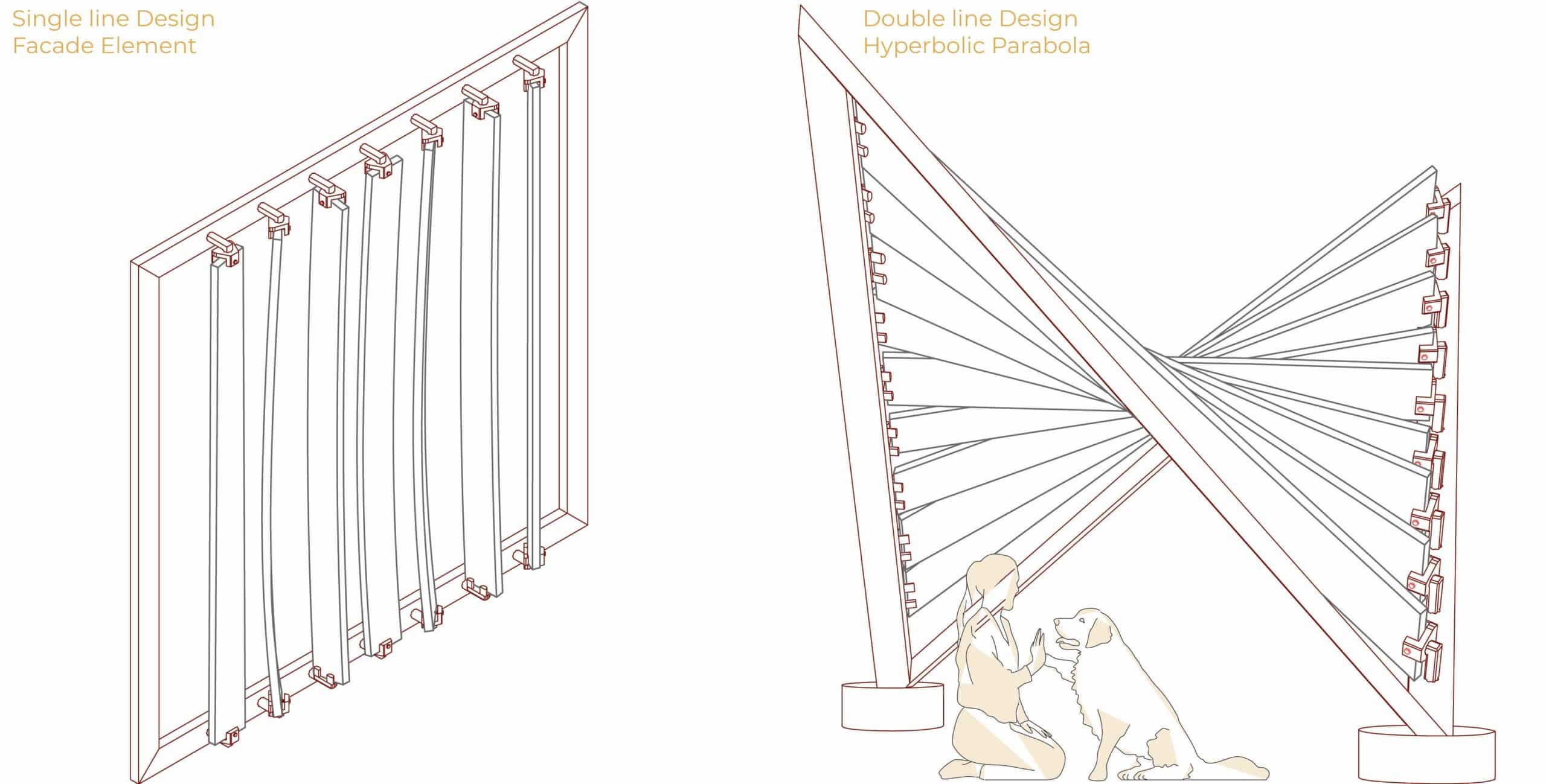
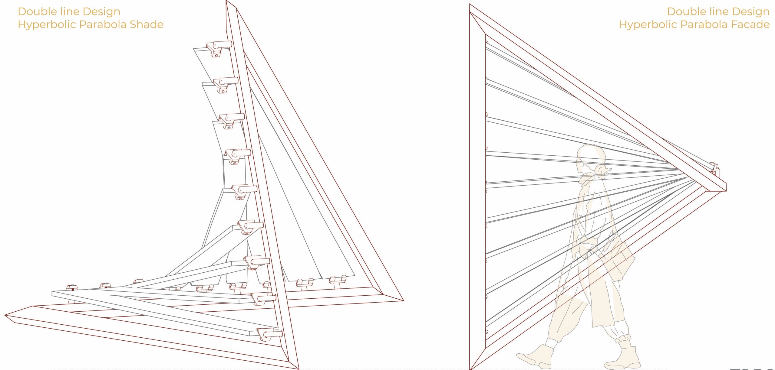
Hyperboloid Paraboloid Design
The final fabrication experiment materialized as a hyperboloid paraboloid pavilion structure, which serves both as a design prototype and a functional test bed for the framing system and warped planks. This double curved surface, generated through two sets of skewed linear connections, provides the ideal geometry to challenge and demonstrate the flexibility and adaptability of the warped wood framing system. By aligning the planks’ natural warping tendencies with the twisted logic of the hyperboloid, the design capitalizes on their intrinsic curvature, minimizing the need for excessive mechanical force or reshaping.
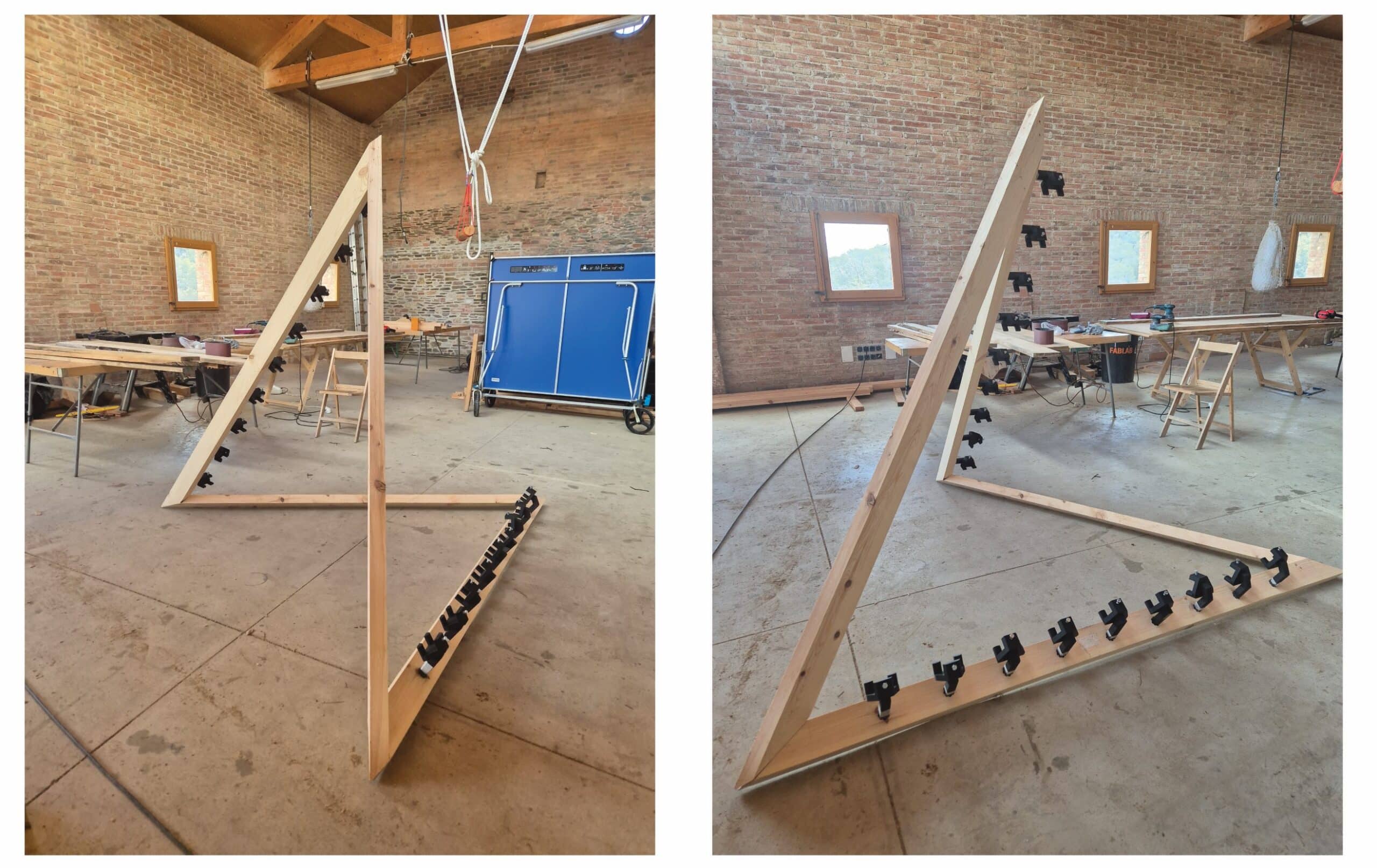
Design and Fabrication
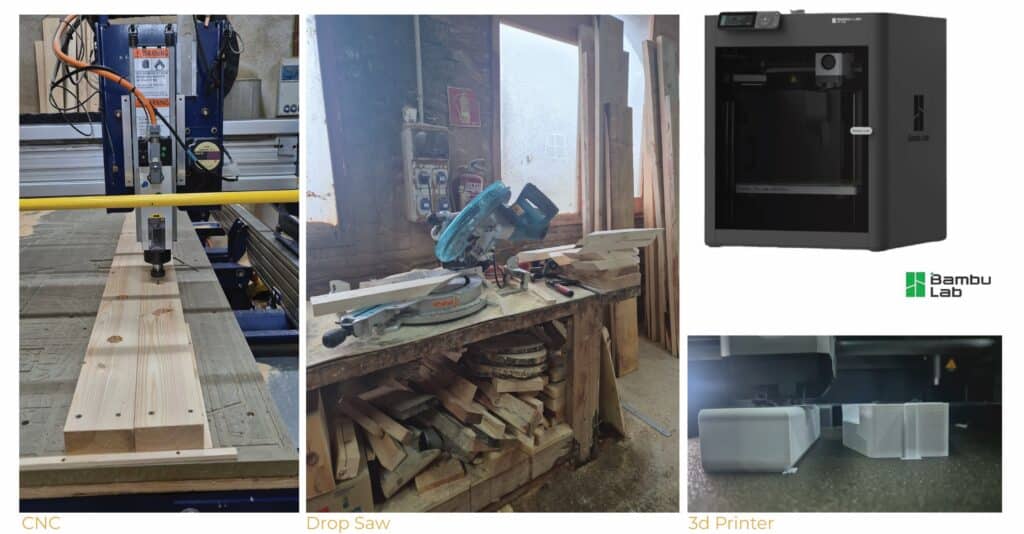
The fabrication of the hyperboloid paraboloid structure began with crafting the four primary frames that define its twisting silhouette. Using a table saw, each frame was cut from pine wood, ensuring dimensional accuracy for structural alignment. Then the star-shaped pattern of peg holes was milled into the frames using a CNC router, providing precise anchor points for the parametric design. Each frame was then cut with a 35° slant cut along the Y-axis and a 55° slant along the X-axis, with a drop saw, enabling the correct tilt and alignment in the final form. The 3D printed frame components were digitally modeled in Grasshopper, and fabricated at IAAC’ main campus.
Fabrication Tools
Once the frames were ready, the digitally measured warped wood planks, derived from the hyperboloid paraboloid Grasshopper model, were trimmed and labeled accordingly. The assembly began by constructing the overall hyperboloid structure with the four frames. Screws were partially inserted into the 3D-printed frames midway, allowing for easier alignment during the next steps. Each printed frame were then placed into its respective position within the wooden structure.
One by one, the warped planks were gently slid into the printed frame slots, allowing their natural curvature to follow the hyperbolic form. Finally, each half-screwed bolt was tightened and capped, securing the planks in place and completing the twisting, doubly curved surface
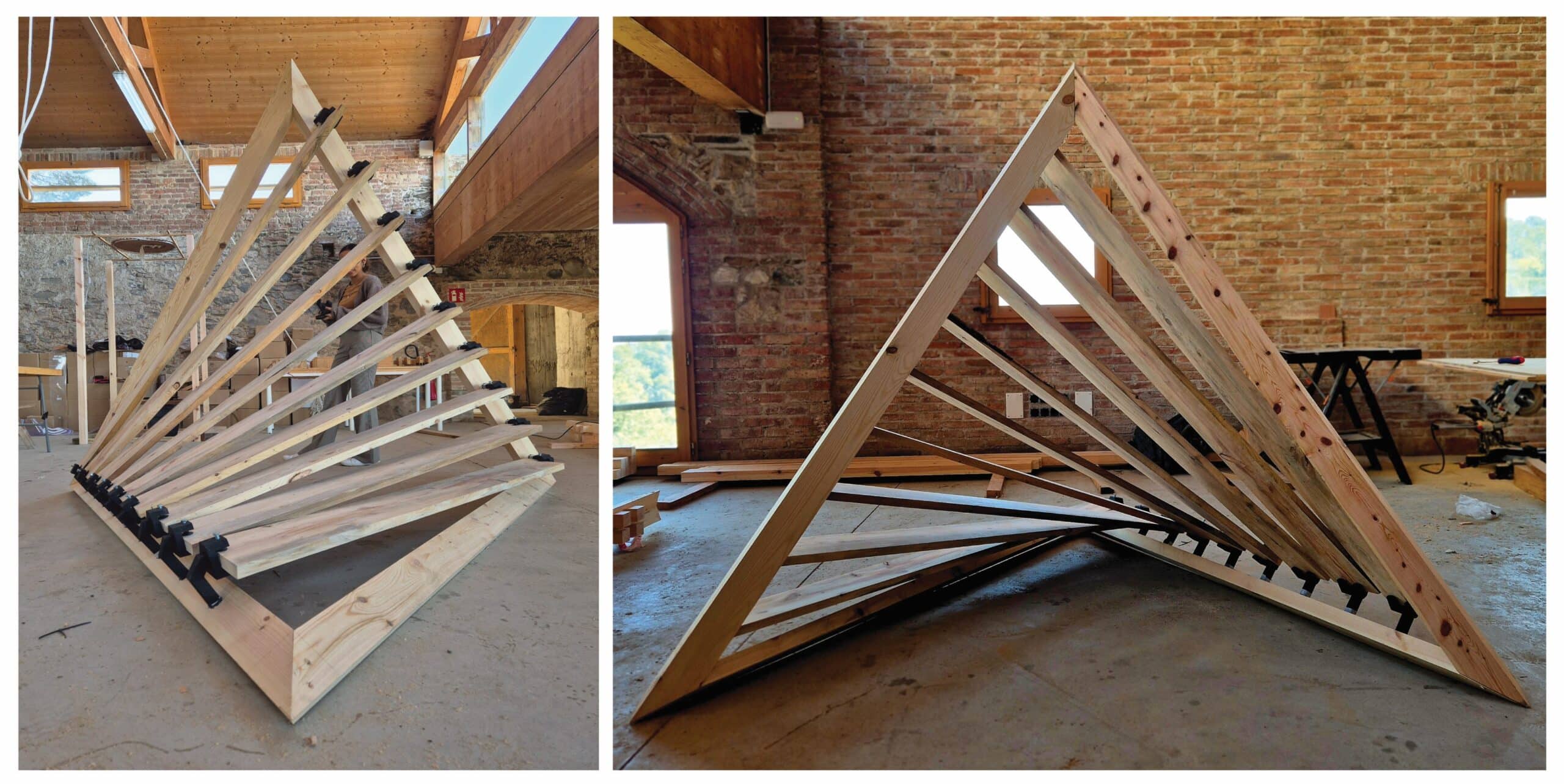
The hyperboloid form thus acts as a proof of concept: it not only tests structural coherence and assembly feasibility but also shows that even irregular, discarded or deformed wood elements can be precisely integrated into sophisticated geometries when paired with a smart parametric support system.
