Additive manufacturing has opened up a vast array of possibilities to the creation of more sustainable but also salable designs that can address critical issues in our environment. In the context of architecture, multi-material 3D printing opens the door for an opportunity to embed intelligence into the surfaces in our built environment through material selection and paring – reducing complex multi-part systems into a single mixed component.
Our concept, Heatwave, utilizes the conductive material properties of graphene to create selectively heated walls/structures. We paired this with clay due to its energy storing properties, low carbon footprint, and printability.
Workshop context:
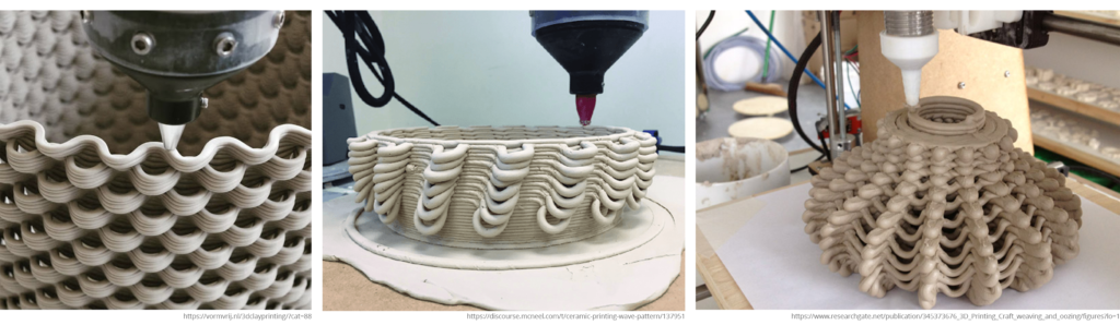
This was a one-week workshop on additive manufacturing, where we learnt to program an ABB IRB 140 – 6 Axis Robot to perform the function of single nozzle, multimaterial 3D printing. The aim was to utilize the rotation of the nozzle to vary which of the two materials was extruded. We used white and red clay as proxy materials as a means of representing the functional advantages of multimaterial additive manufacturing.
Multi-material 3D printing
3D printing has been a game-changer in the world of manufacturing, enabling us to create intricate and complex structures with unprecedented precision. However, the exploration of multi-material printing, especially in the context of robotic multi-material printing, is still in its early stages. One groundbreaking project that has garnered attention is the Janus project at Harvard, which shares similarities with our work. This project involves the simultaneous mixing of two clays through a nozzle, resulting in the creation of intricate patterns. With the appropriate materials, it can become an incredibly effective tool.
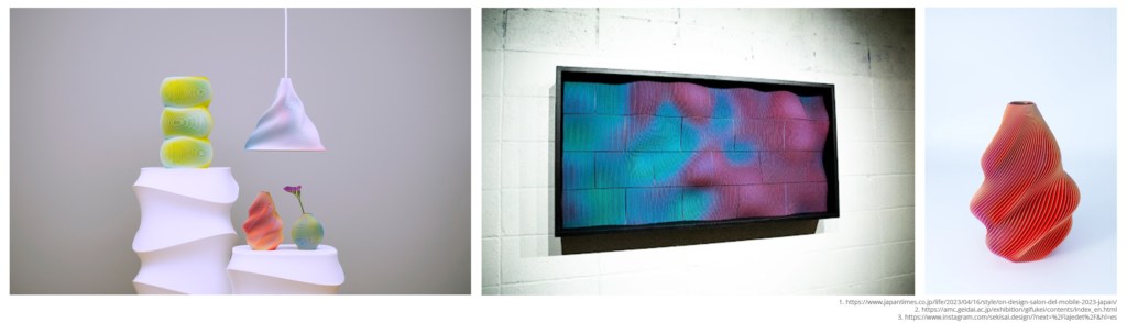
Furthermore, studios such as Sekisai have been at the forefront of this technique, exemplifying its potential by crafting optical illusions, even though their processes do not incorporate robotic arms. For this workshop, we had the opportunity to talk to Soya Eguchi from Sekisai about the way they create the color changes and utilize them in the printing process.
State of the art – Graphene Components:
One significant aspect of our project involves the use of graphene, a material renowned for its exceptional electrical conductivity and heat-dissipation qualities. Extensive research has consistently demonstrated its strong performance in these applications. In a notable experiment conducted by Ricardo Mayor Luque, where current had been passed through a graphene block, as shown in the accompanying youtube video. The outcomes from the tests show how quickly the transfer of heat occurs between the graphene and clay.
That study also included an efficiency comparison, revealing that the heat generated by the graphene-infused brick, when power is applied, is sufficient to make it a competitive option in terms of power consumption compared to existing heating systems, and in many cases, even superior.
Design Process:
For the design, we embarked on a journey to explore the capabilities of the single-nozzle multicoluor Clay 3D printing. As the first class to work with this innovative tool, our goal was to challenge the abilities of the robotic arm and end-effector, our programming skills and deliver a interesting concept.
To test the limits of the material, we created a structure with a distinctive S-shaped movements in each layer when viewed from the top. The S-shaped curves mean that the Robot prints in mid air at some point. Below are some examples:
Inspiration:
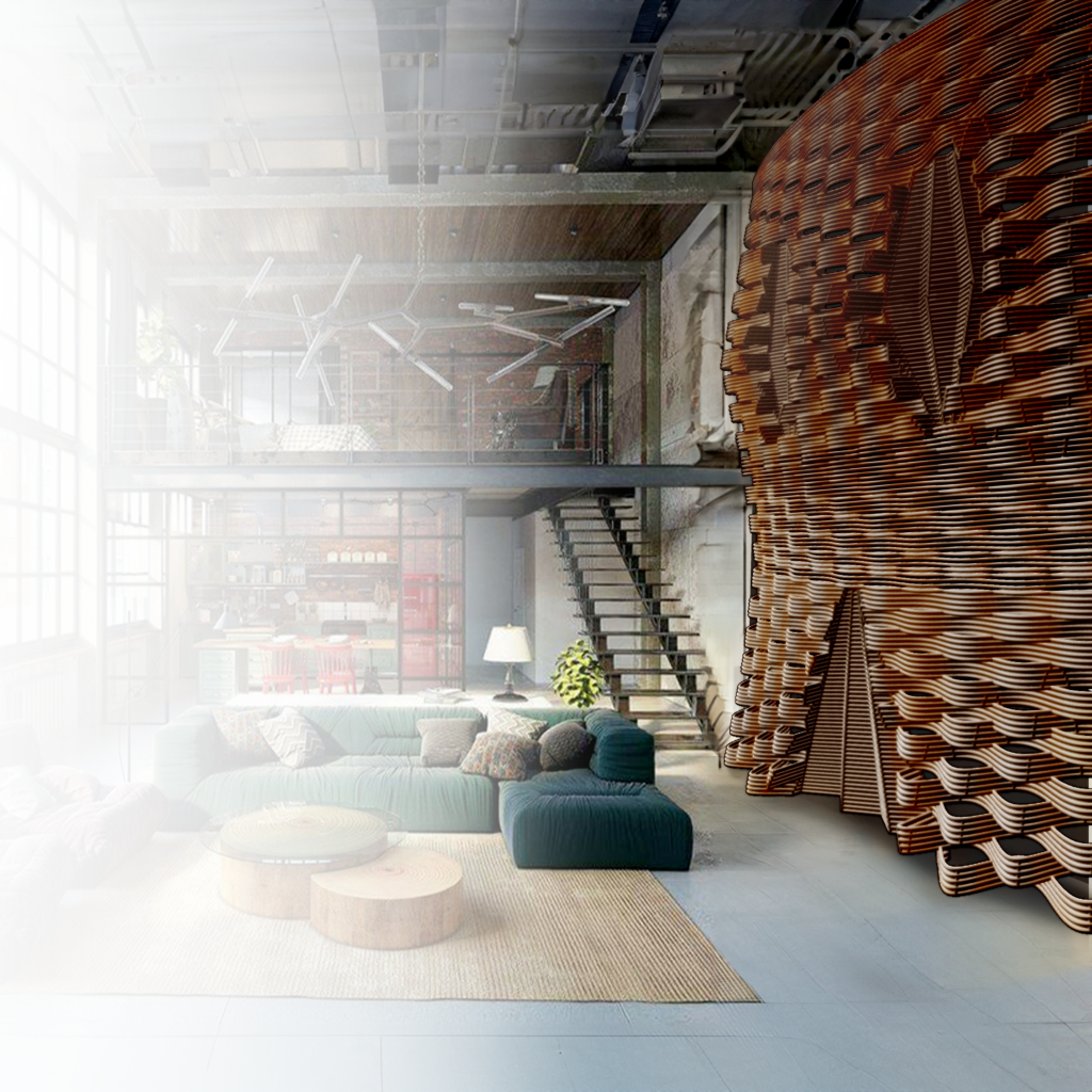
While we all liked the challenge of the wavy design, we also considered it a good way to demonstrate the graphene’s ability to selectively heat. The movement presented a unique opportunity to experiment with the color-changing capabilities of the filament. The waves in the wall, in addition to their aesthetic appeal, also serve a functional purpose – acting as radiators to provide targeted heat where needed.
The appearance can be controlled by adjusting the robot’s speed, the depth of the “S”, and the clay mixture. We only had control of the first two, and additionally had to manage the rotation of the end effector to dispense the color/graphene where desired. To better understand this, we created a test print and evaluated its parameters with the printed version.
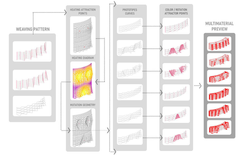
Once we felt confident with the ability to change the colors and create the desired appearance of the design, we proceeded to create our final design. Due to the limitations of the cartridges of the end effector, the design had to be vertically split into six different pieces, each 70mm tall. The diagram below illustrates the design process. While we aimed to highlight variations of the wavy pattern, we also needed areas where the graphene energy would be introduced into the structure. These areas are indicated in the second column of the diagram under “heating attractor points”. The points are meant to have a higher concentration of white clay/graphene to distribute the heat from those points.
Printing:
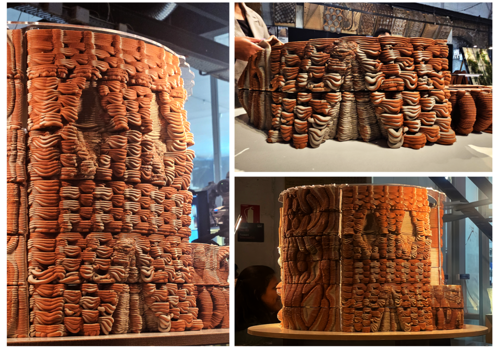
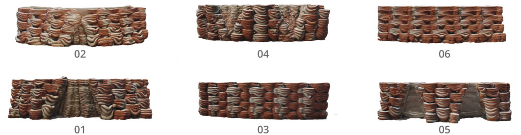
The final printing process went as expected. Throughout this process, refinements were made as experience was gained with each printing iteration. Nevertheless, in each of the components, the established pattern is visible, inducing a sinuous wave effect that results in material deposition on the surface. In this case, the gray material represents graphene, while the rest is clay. This serves to validate the proper functionality, as the gray material aligns with the predefined points in the temperature simulation.
The prints turned out as expected but there were some learnings along the way. In prints 01, 02, and 04, there are visible cavities. Due to the amount of curves in those cavities, along with the desire to have them in one color, the robot was very slow in those areas, dispensing much more material than desired. We decided to address this in print 05, where we removed the zigzag pattern inside and made the lines straight. Additionally, during printing, we learned the maximum value we could print in the air, considering our material, print speed, etc. In prints 01 and 02, a lot of drooping can be seen in the curves, which is much less pronounced in prints 03 and 06. If we had the ability to reprint, we would try different material compositions and adjust some other variables to further match the outcome with the virtual representation.
Technical Table:
The table below highlights the times it took to print each of the six prototypes for the final Model. It highlights the outcomes in terms of time, material expenditure, linear meters of printing, and volume. These values are quite similar to one another, primarily owing to the uniform size of the components.
Final Outcome:
Over the course of this project we wanted to strike a balance between learning processes of control with robotic 3D printing and some of the known design languages that comes with it this way of fabricating – such as looping surface textures, working with attractor points to achieve a gradient texture, and the process of transitioning form curved to straight-line tool paths.
In our early prints we experienced some issues with material buildup in areas where the detailing of our model resulted in an over saturation of lines, making the twist and pivot in a particular zone. In the later stages of the workshop we were given the opportunity to print 2 more bricks for the tower – in this instance we refined our previous prints so that material buildup was avoided – this can be seen in the top two bricks of our tower.