
State of the Art
In recent decades, kinetic facades have surfaced as innovative architectural elements, offering alternative building envelopes tailored to address escalating and intricate demands related to user comfort, energy consumption, and cost efficiency. Various articulations of this concept have been advanced, encompassing approaches that span from the integration of inventive components to the deployment of highly intricate designs and advanced technological applications.
The essence of kinetic facades lies in their capacity to dynamically respond and adapt to shifts in environmental conditions. The design and assessment of such facades constitute a complex undertaking, involving interactive kinetic elements embedded within three-dimensional, dynamically evolving physical components.
In this exercise photoresistors and microphones were explored as sensors in order to explore a Kinect surface that would self shade itself or function as a sound reflection wall according to each sensor. Analogic Data was collected from the sensors, processed and transferred to angle rotation of servo motors. This exercise aimed to understand the realm of design interoperability and capabilities of sensors into informed and environmental performative design.
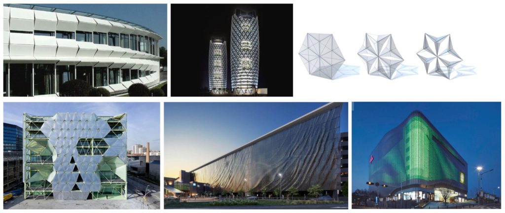
Figure 1 – In order (from left to right, top to bottom): Kiefer Technic Showroom by Ernst Giselbrecht; Al Bahar Towers by Aedas Architects; ICD Media Center by Enrique Ruiz Geli; Brisbane Domestic Terminal CarPark by Ned Kahn + UAP; Galleria Centercity by UNStudio
Light :
System Workflow
The primary workflow of this Kinect surface prototype involves the integration of photoresistors and microphones to process analog data, subsequently informing the angle rotation of servo motors. Sensors are strategically positioned across the surface, triggering rotations from servo motors on adjacent surface modules.
Given the experimental objectives, a modular three-dimensional system was imperative to facilitate the facile bending of the surface, enabling the creation of peaks and valleys on the facade. This capability allowed for the exploration of self-shading performance and the potential of a reflective sound panel.
Numerous testing prototypes were conducted to ascertain the optimal bending system. Various materials, such as balsa wood and fabric, were examined in different configurations—tests encompassed fabric with glue, balsa wood with diverse modules, sandwich layering incorporating fabric, balsa wood, and fabric, exclusive use of balsa wood, and incorporation of elastic thread and sewing techniques. Findings revealed that, while several methods achieved bending, they were limited to affecting only one module at a time, rendering them suboptimal for generating the desired effects for a self-shading system or a reflective sound panel.
In light of the insights gained from these preliminary prototypes, a modular system employing origami principles was conceived. This design aimed to induce a chain reaction, wherein the regional scale module, pushed by servo motors, influenced adjacent modules. A pyramidal/origami system was subsequently devised and fabricated to create a facade with enhanced bendability.
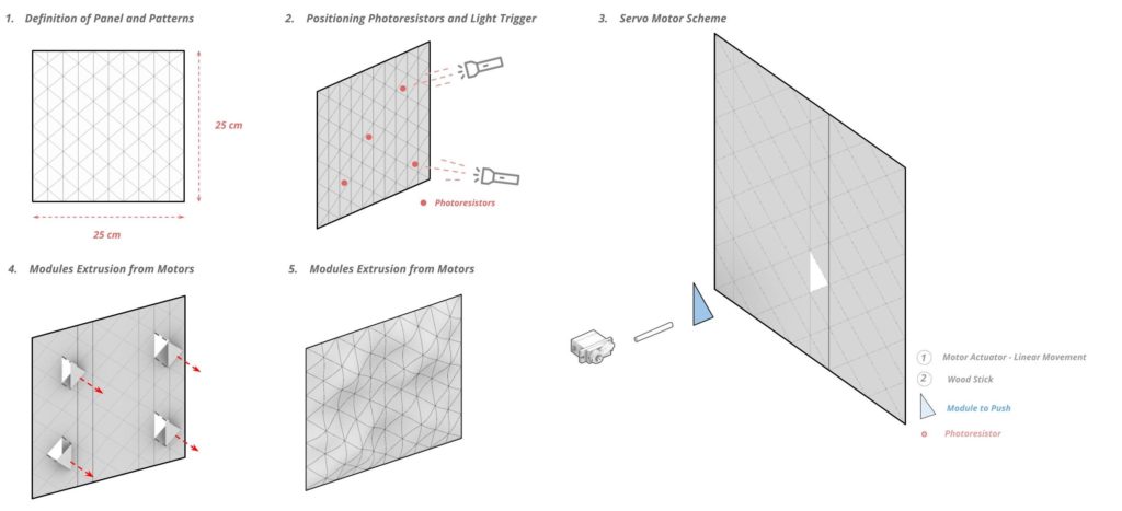
Figure 2 – Relationship between kinect system and photoresistors
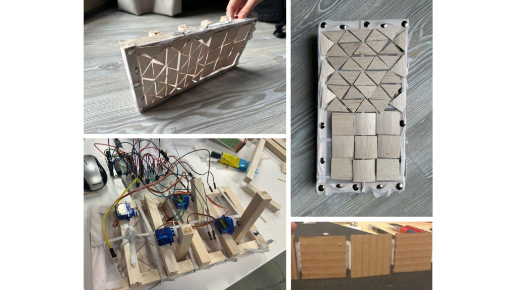
Figure 3 – Testing Materials and Bending Surfaces with Servo Motors
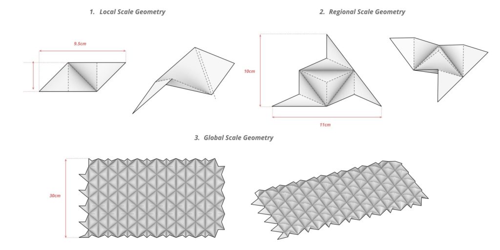
Figure 4 – Origami to Bend Surfaces From local Scale to Global Scale
System Anatomy
To integrate the origami surface and the associated hardware system, a layered structure was conceived and constructed. A wooden frame was implemented as the principal structural system to provide support for the origami facade. Additionally, a wooden substructure was devised to house the breadboard and the Arduino microprocessor.
Examining the circuitry, photoresistors were strategically placed on the outer side of the facade to capture data pertaining to light and shadow. Servo motors, equipped with a pushing mechanism utilizing fishing net and balsa, were positioned in modules adjacent to those housing the photoresistors.
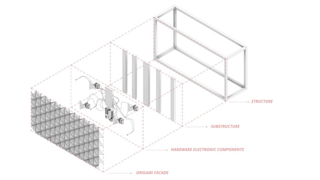
Figure 5 – Bill of Materials and System Parts
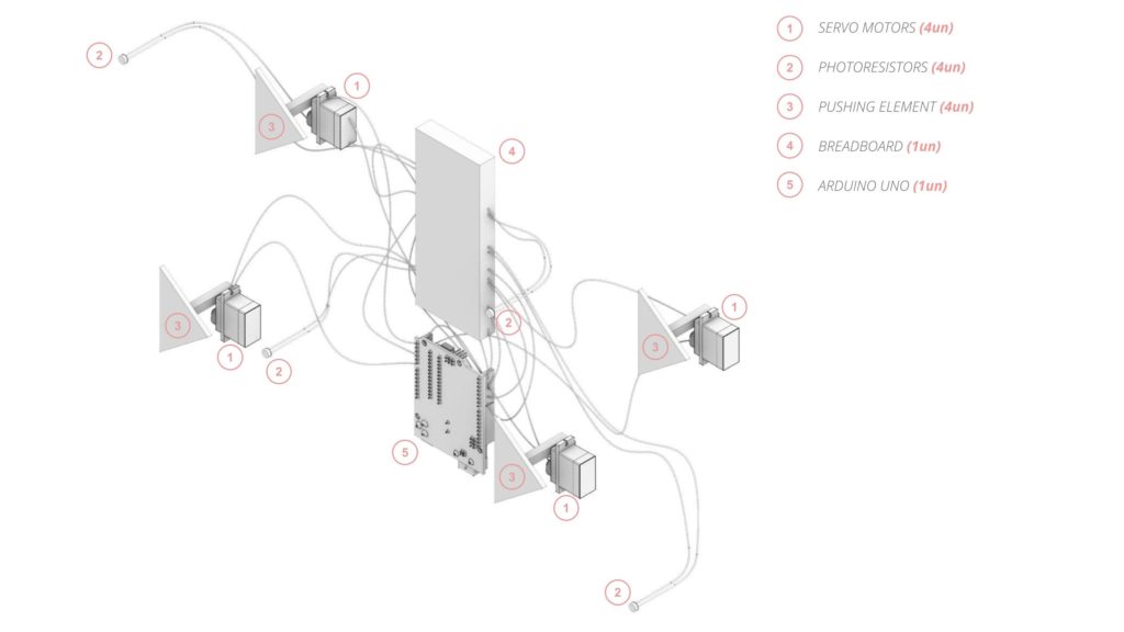
Figure 6 – Organization between Photoresistors and and Servo Motors
System Logic
Our primary hardware configuration comprises four servo motors and four photoresistors, with the latter serving as the primary input source. The photoresistor light detection values undergo a crucial preprocessing step wherein they traverse a threshold, facilitating the categorization of values to effectively govern the rotation of the servo motors. It is imperative to emphasize that each servo motor operates independently, with each photoresistor uniquely responsible for controlling an individual servo motor. This autonomous functionality ensures precision in the manipulation of each motor based on the corresponding photoresistor’s input.
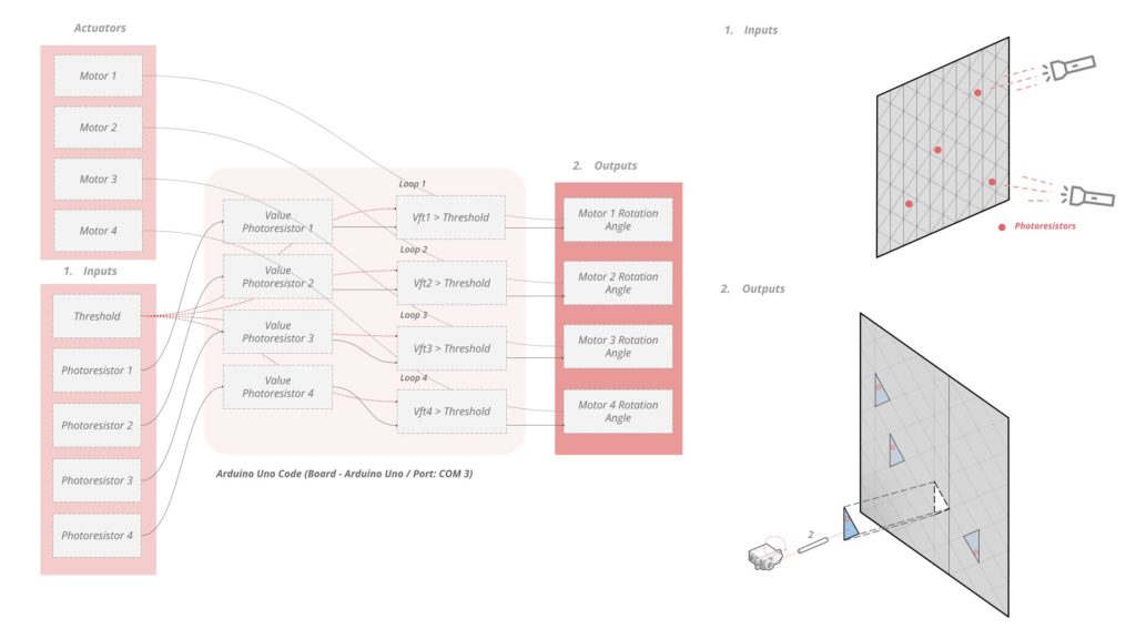
Figure 7 – Pseudo Code Arduíno
Consistent with this operational autonomy, the circuitry is intricately organized in parallel configuration, aligning with a one-to-one relationship between each photoresistor and servo motor. This parallel connectivity enables real-time determination of distinct values, translating into rotational angular inputs for the servo motors. The deliberate independence embedded in the system’s design is indispensable for the seamless functioning of the facade system. This design choice guarantees that the performance of each servo motor is isolated and unaffected by the operation of others, contributing to the overall reliability and effectiveness of the shadow facade system.
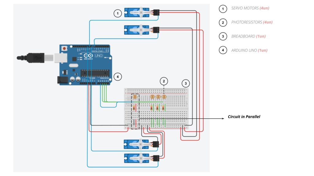
Figure 8 – Circuit Schematic
System Performance
Various angular rotations and light intensities were systematically investigated to assess their impact on the behaviors exhibited by shadow facade systems. The initial phase of experimentation involved adjusting the motor rotation from 90 to 135 degrees. This variation aimed to discern the most optimal pushing motion, taking into consideration the inherent elasticity of the material and the characteristics of the hardware components. Notably, the rotation at 135 degrees demonstrated superior accuracy in executing the facade, signifying its potential as the preferred configuration.
Figure 9 – 90 degree rotation
Figure 10 – 135 degree rotation
In a subsequent experimental iteration, the light detection values of the photoresistors were inverted to gauge the system’s response when exposed to both light and shadow. The outcomes revealed a remarkable similarity in system behavior under these distinct lighting conditions, affirming the versatility of the hardware components employed in the system.
Figure 11 – Range with Light (over 600)
Figure 12 – Range with Shadow (under 500)
To enhance the scope of our analysis, we integrated the Arduino Uno board with the FireFly Grasshopper plugin. This integration facilitated the extraction of light values and enabled the simulation of facade performance across diverse patterns and applications. This approach transcended the limitations of relying solely on physical models, providing a significant advantage. Leveraging FireFly allowed us to digitally optimize performance and mitigate potential errors in the physical fabrication process, thereby enhancing the overall robustness and efficiency of the shadow facade system
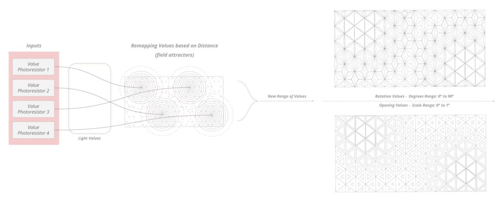
Figure 13 – Pseudo Code from Arduíno to Firefly
Figure 14 – Informed data from sensors to Firefly
Sound :
System Workflow:
As mentioned in the aforementioned workflow, we have tried to develop a system that uses both sensors (Photoresistors & Microphones) to obtain the analogue data from them and subsequently manipulate the servo motors based on the inputs.
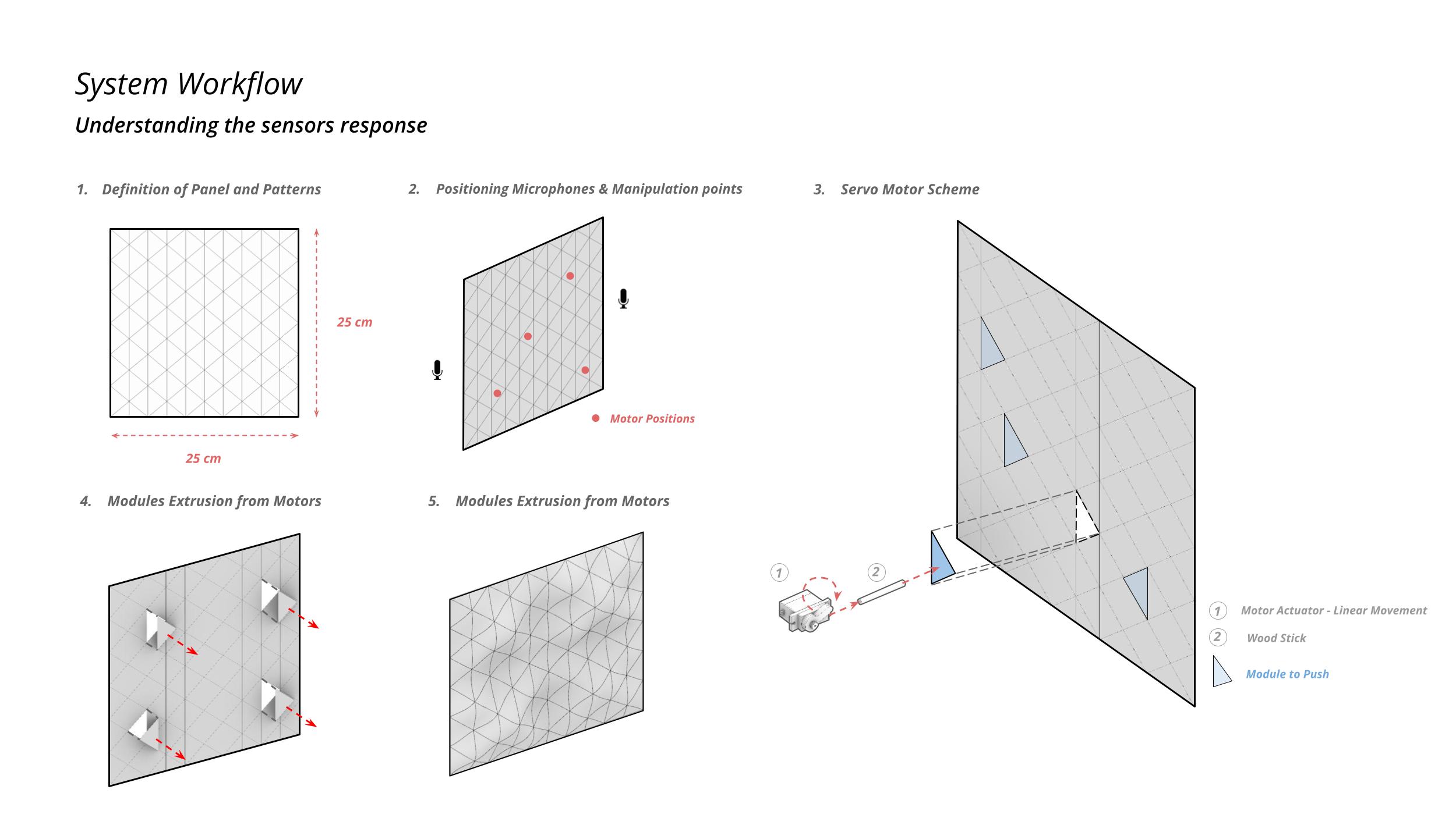
Figure 15 – Relationship between Kinect system and Microphones
System Anatomy
As shown in Figure 16, a layered structure was conceived and constructed to integrate the origami surface and the associated hardware system. A wooden frame was implemented as the principal structural system to provide support for the origami facade. Additionally, a wooden substructure was devised to house the breadboard and the Arduino microprocessor.
Examining the circuit, Microphones were placed on both ends of the wooden frame to capture the analogue data from different directions. One Servo Motor has been placed strategically with a combination of gear systems to facilitate the movement of the facade. We have also developed a Piston & Shaft mechanism to manipulate the facade based on the rotation of the servo motor.
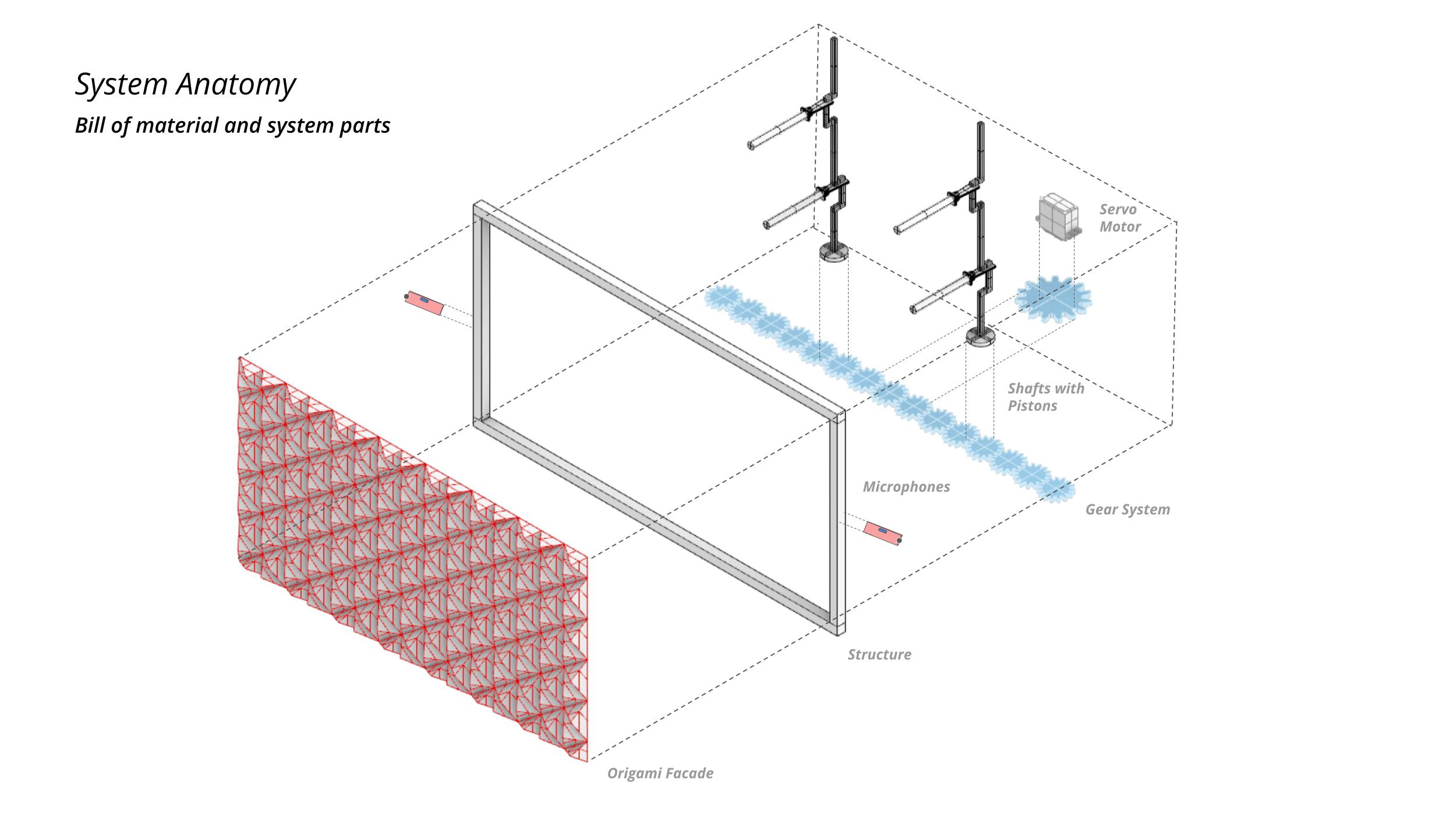
Figure 16 – System Anatomy of the Sensors and the Facade.
System Logic
We started with a simple logic that takes analogue inputs from the microphones and converts them into data that will be the input for the manipulation of the servo motor. The same is shown in Figure 17.
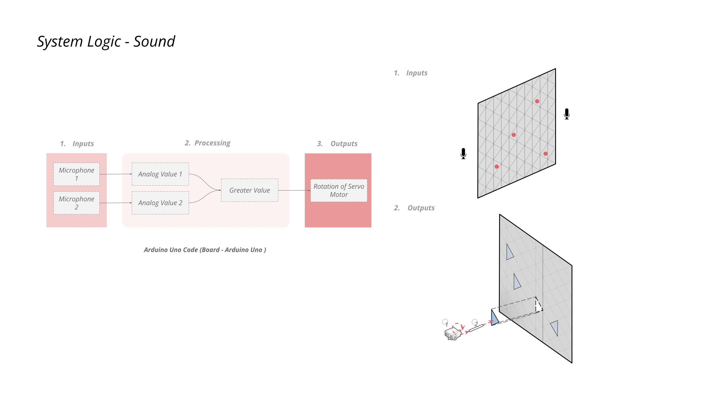
Figure 17 – System Logic for the Microphones
The above Logic had a lot of complications, such as the sensitivity of the microphones had to be individually calibrated and kept at almost the same values. If the microphones are not calibrated to the same sensitivity, then in most of the cases, output from one microphone will be greater than the other, and the intended output will not be produced.
Therefore, we came up with another logic.
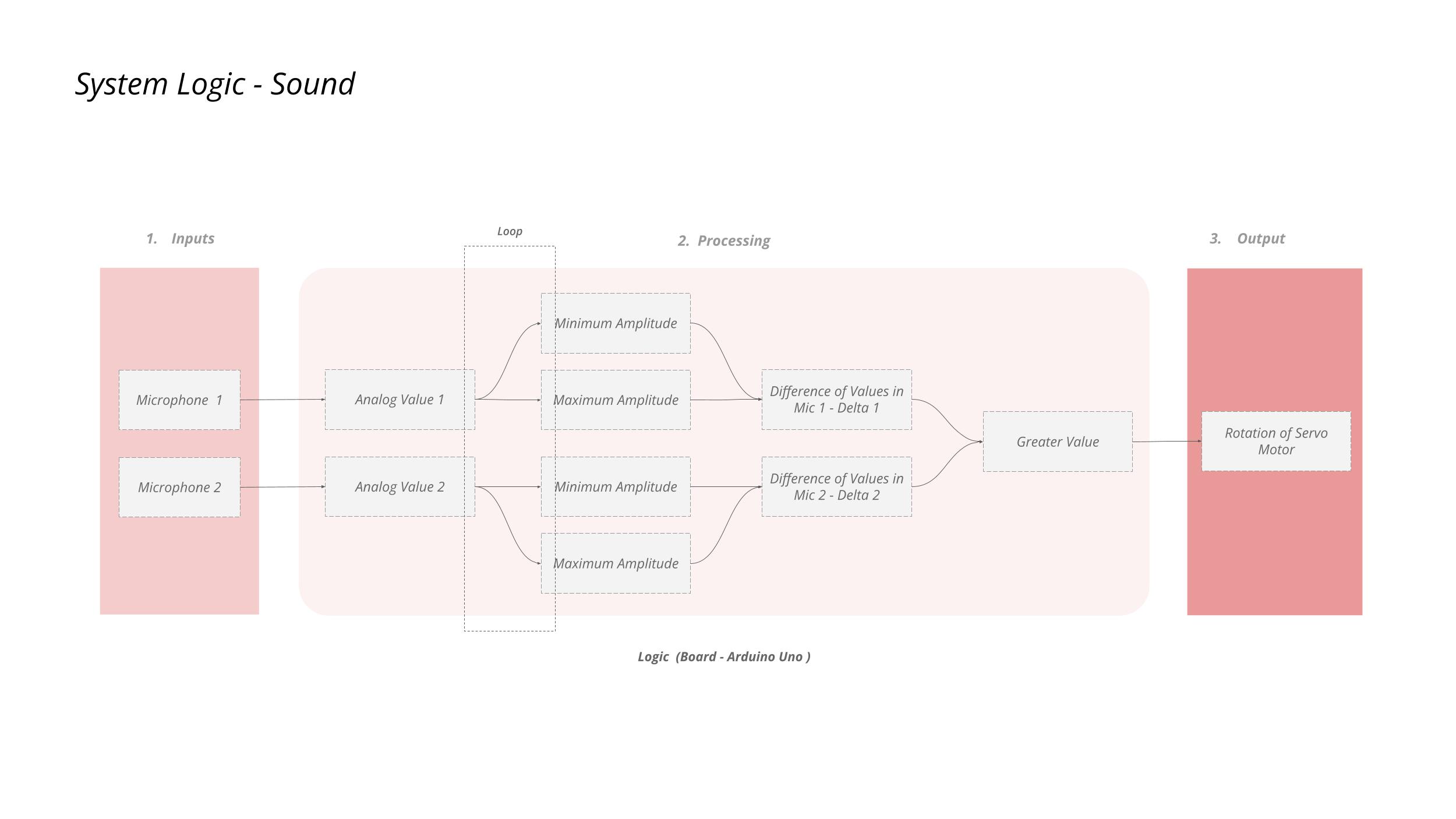
Figure 18 – Updated System Logic for Microphones
As shown in Figure 18, we have updated the code to take input of a loop of values from the microphones and output the maximum and minimum outputs from them. Then, the difference of these 2 values (Delta) will be considered for the manipulation of the Servo Motors.
The definition of the loop is such that “For every ‘n’ milliseconds, take ‘n’ inputs and output the minimum and maximum values from the list”.
This updated code has given us the following conclusions:
- The idea of the Sensitivity of the Microphone can be neglected here.
- Gives a better understanding of the change in Amplitude.
- But it only works for Instantaneous sounds like Claps.
System Circuit Schematic
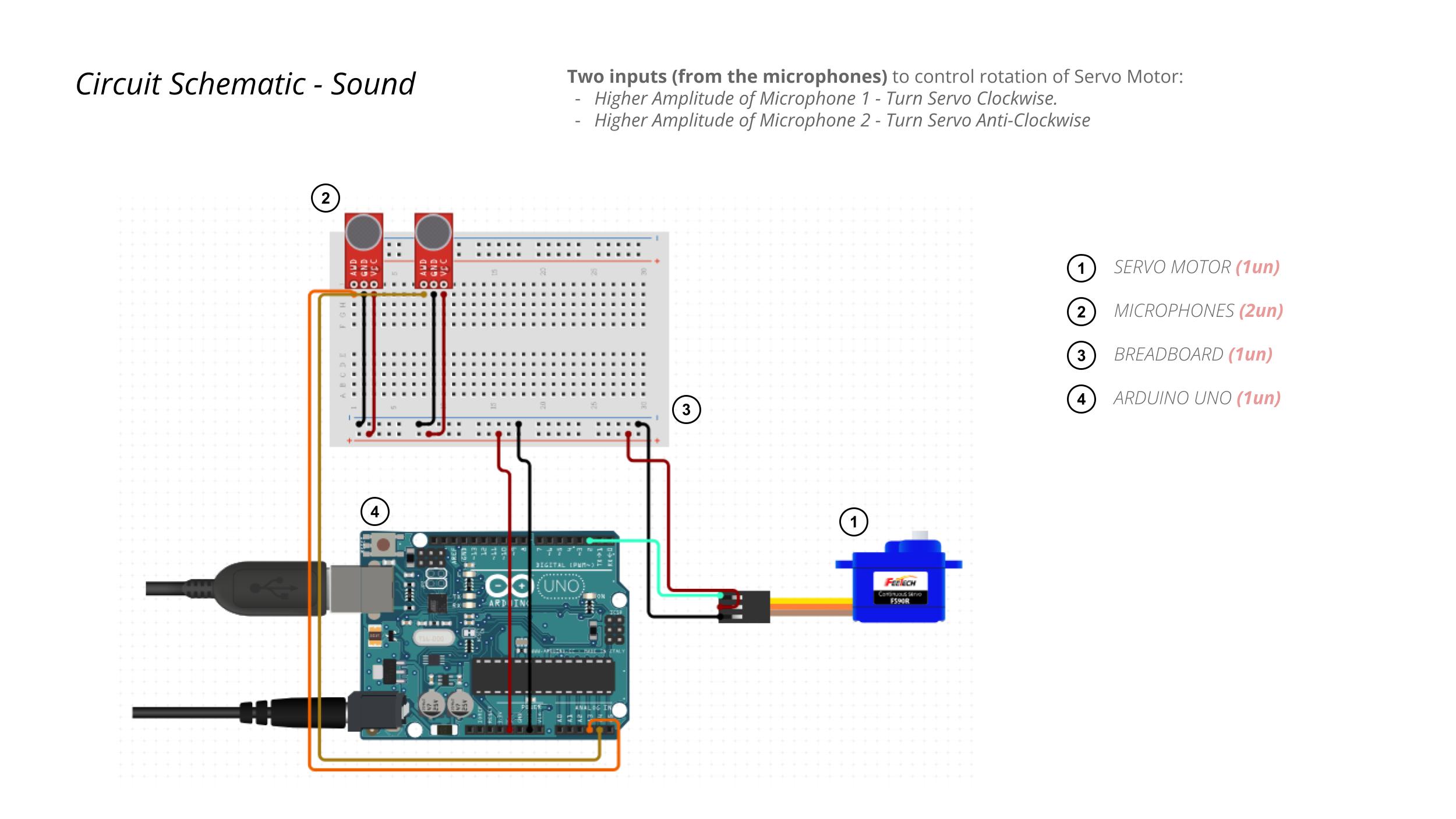
Figure 19 – Circuit Schematic for Microphones
System Response
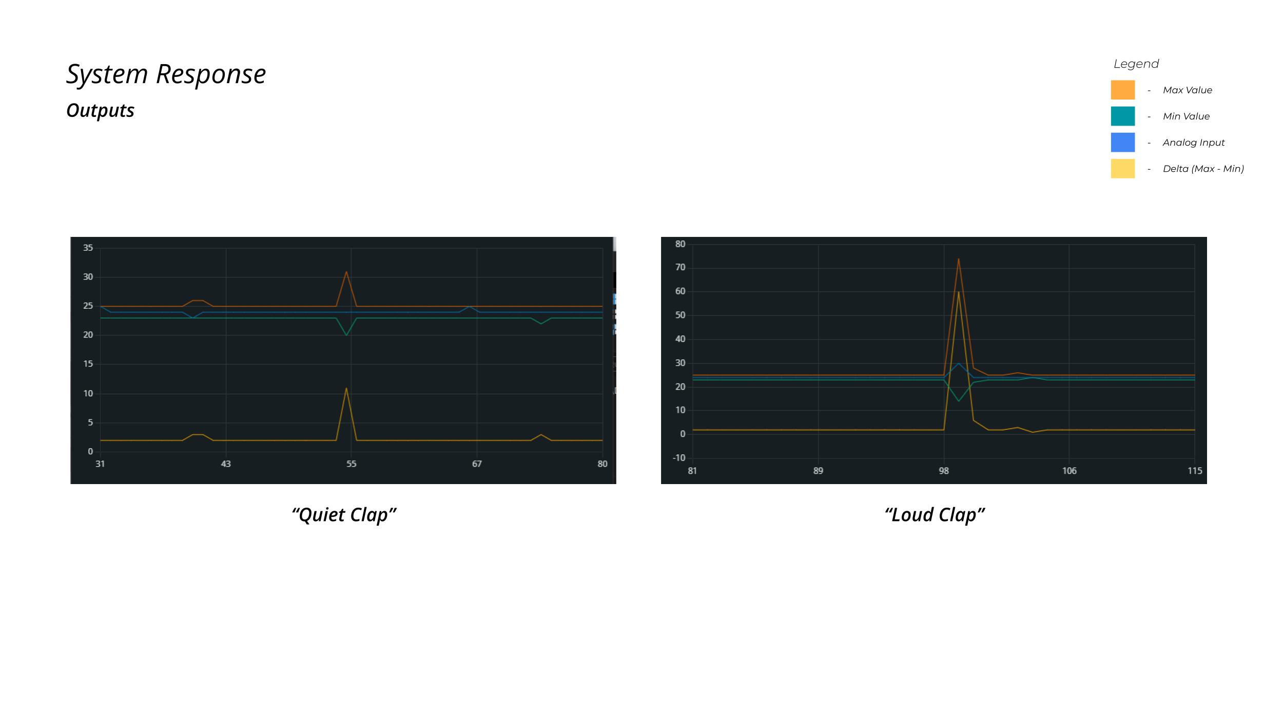
Figure 20 – System responses for the Circuit.
As shown in Figure 20, we have different outputs for different sound inputs. The former output was for a quiet clap aimed at the microphone & the latter is the output for a loud clap aimed at the microphone.
Prototype
During the fabrication, we faced a few issues, as the piston in the shaft did not have enough force to push the origami Facade. We came up with another solution, i.e. a fabric over a wooden frame. This allowed the pistons to move easily and generate the pattern as estimated during the thought process.
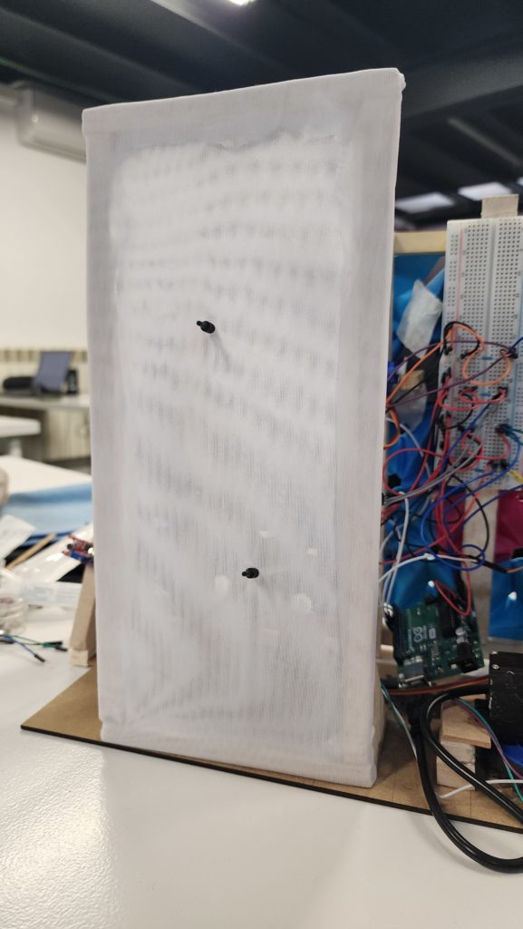
Figure 21 – Fabric on the Wooden Frame.
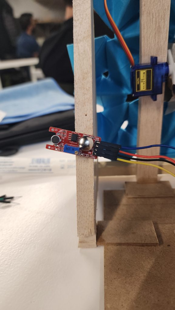
Figure 22 – Microphone on the Edge of the Wooden Sub-Structure.
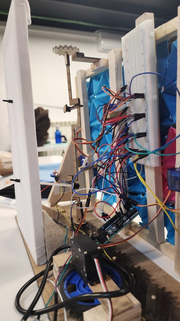
Figure 22 – View of the Wooden Shaft & Pistons.
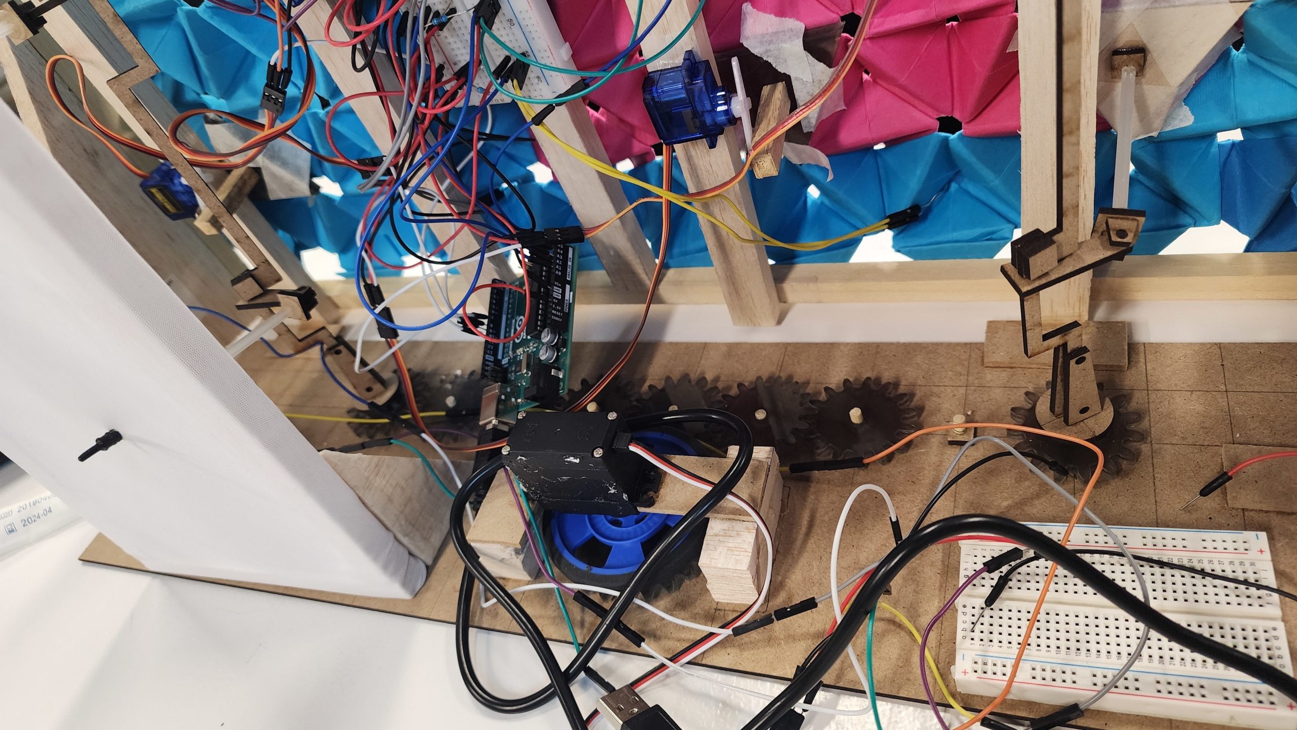
Figure 23 – View of the Servo Motor and the Gear system for manipulation of the Facade.
Further Steps
Self Shading system
To obtain tangible data from the physical model for digital analysis, a meticulous 3D representation of the physical model must be generated. This enables the testing of various pushing methods and facilitates the subsequent performance of radiation analysis utilizing tools such as Firefly and Ladybug. On the hardware front, optimization of the circuitry, with a focus on minimizing cable usage, becomes imperative to effectively scale up the facade to an architectural level.
Sound Manipulation Facade
To further the process of our system, we asked ourselves a few questions & statements like:
- Can we record the sound data for other types of outputs?
- Can more than instantaneous sounds be detected using the same Hardware?
- Use a button to initiate the start and stop of recording to save data stored.
- Adapt different gear sizes to control speed.
- Having a lightweight facade or sturdier shafts and pistons for movement of the Panels.
- Multiple Motors to increase the strength of rotation?
Real-Life Implementations
Sound System :
This system of using microphones to manipulate the servo motors can be used in a variety of applications. A few are mentioned below:
- Interactive Art Installations : The project can be used in interactive art where the movement of the art piece changes based on the ambient sound or music.
- Assistive Technology : It can be used to develop devices for people with disabilities. For instance, a device that can open a door or window based on specific sound commands.
- Sound Activated Toys : The project can be used to create toys that move or perform actions based on specific sounds or voice commands.
- Home Automation : It can be used in home automation systems where certain actions are performed based on sound triggers. For example, curtains that open or close based on specific sound cues.
- Industrial Automation : In industrial settings, the system can be used to automate certain tasks based on auditory cues.
Well to conclude, the possibiliteies are endless when explored & largely depend on creativity and the specific needs of the end-user.
