As part of the studio project brief, we had chosen to look at the design of a mining facility on Mars. The proposal looked at a series of semi submerged, subterranean cliff dwellings that would be connected under the surface by a network of mines. The brief of the integrative modelling seminar would be to bring this design from the computational model into Revit to allow us to produce construction information and schedule quantities of project elements to provide an understanding of the cost of the project.
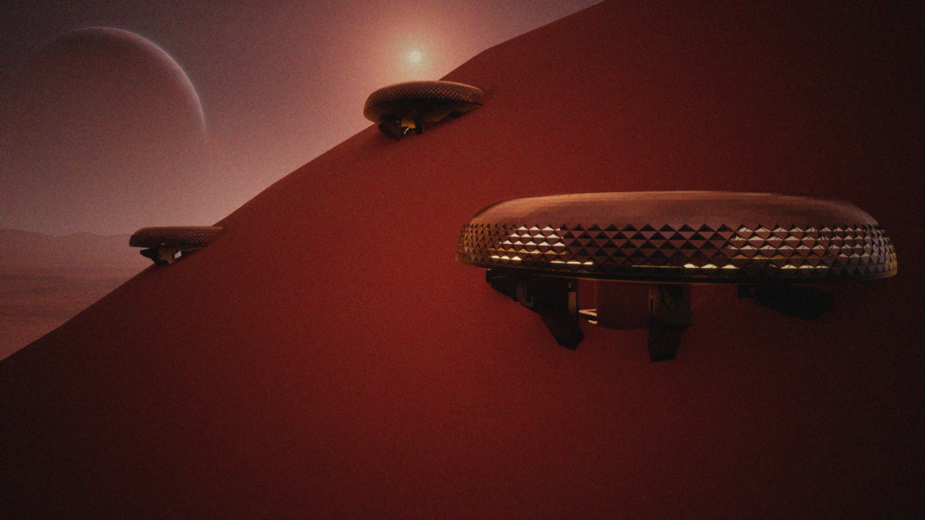
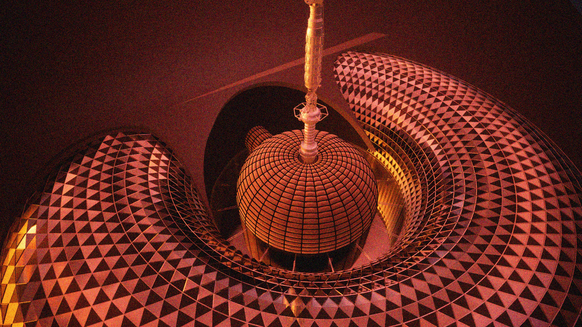
Concept visual of scheme, Elements moved from Rhino/Grasshopper to Twinmotion
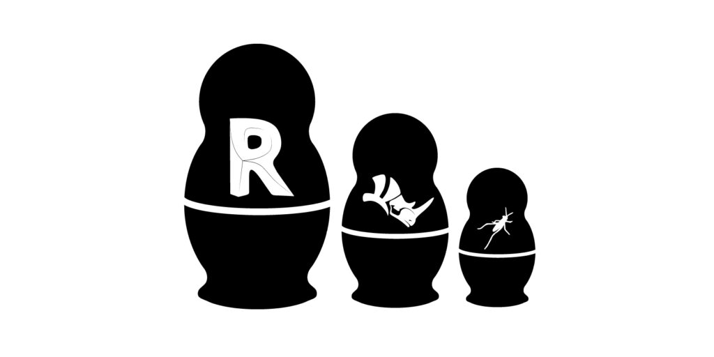
Project Layers
Rhino Inside Workflow
As part of the Integrative modelling seminar, we taught how to use Rhino.Inside to bring complex geometry across platforms as native elements. During the seminar we were shown how to extract information from the grasshopper model and append it to the geometry during the transformation to create Revit parameters that would allow control of the newly created components once inside the platform.
Topography
As part of the course, we were shown how to move meshes from grasshopper to Revit as native topography elements. This workflow can be seen below.

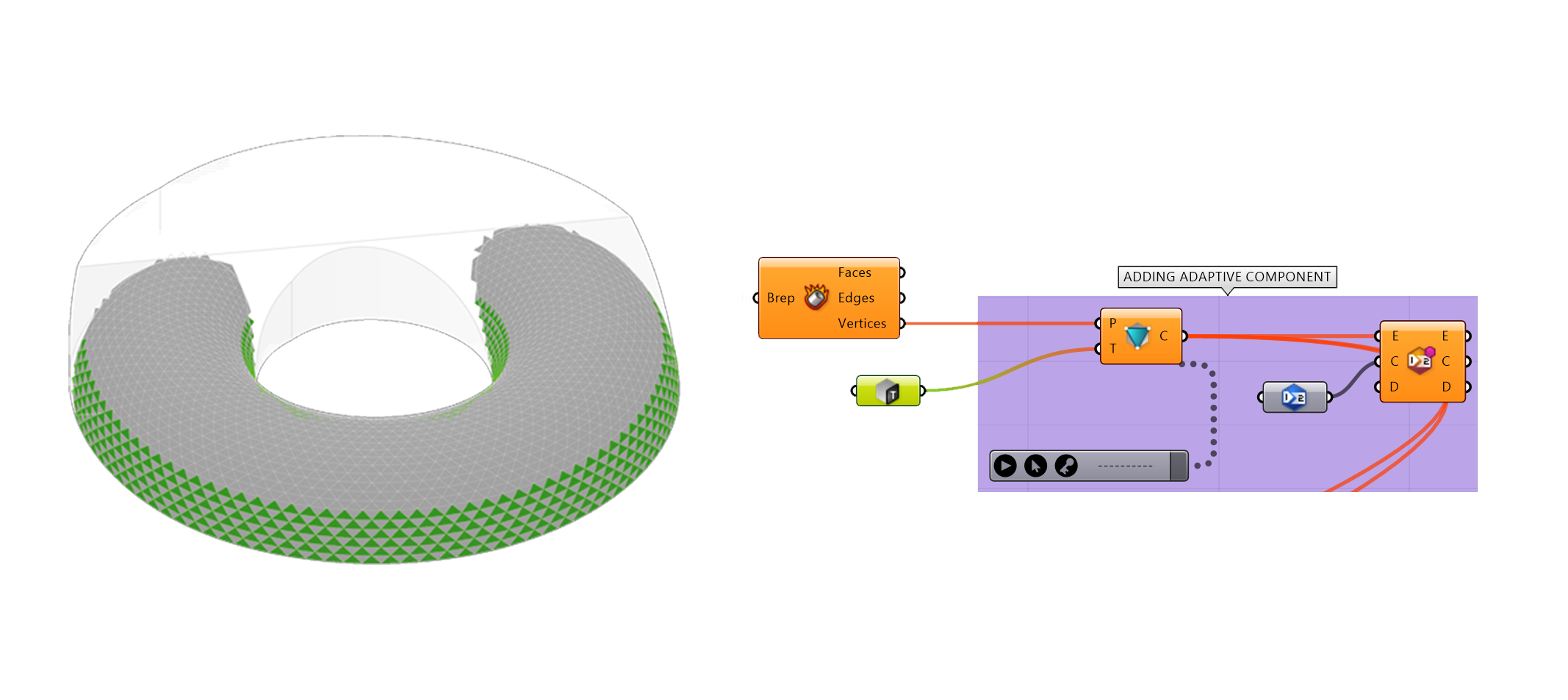
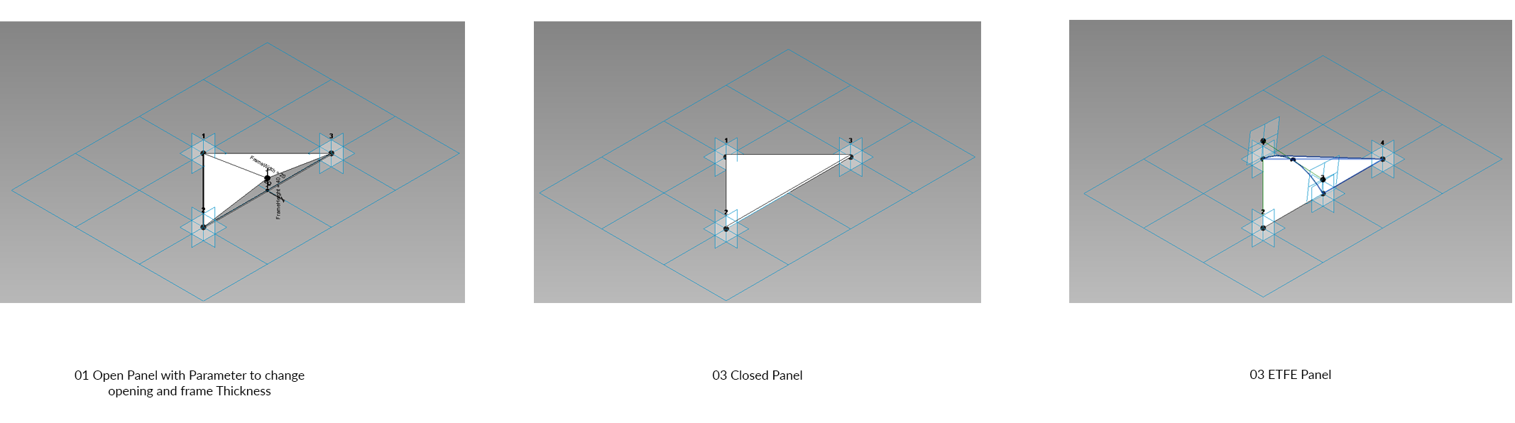
Surface Geometry (Panels + Structure)
We also made us of the adaptive geometry component to work with our grasshopper geometry. A number of custom Revit panels were made for the project (as seen below). The models surface was interrogated and panels were selected based on their surface normal. Downward facing panels were then selected and the open panel applied. Closed panels were applied elsewhere and ETFE used on the circulation geometry as seen further down in the documentation.
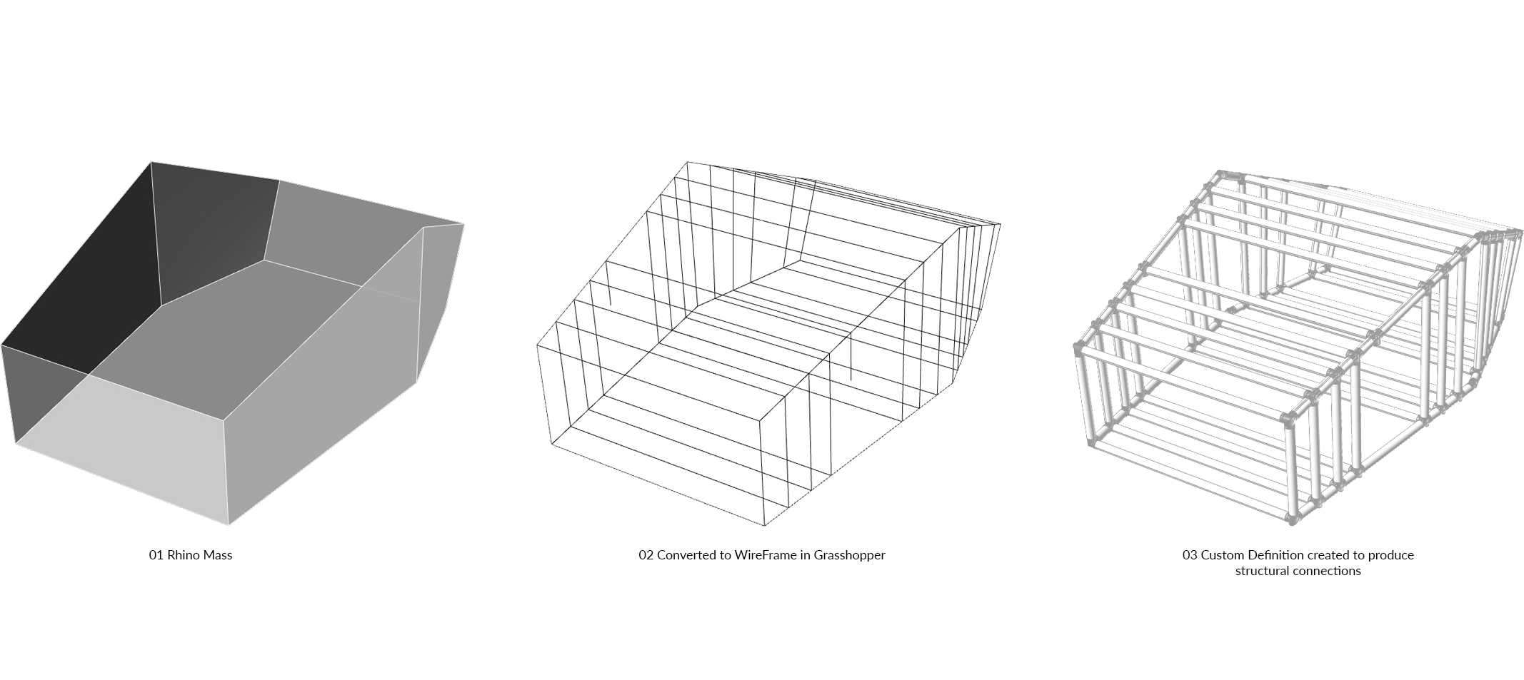
Pods
One issue we had found when moving from Rhino to Revit was the connection detail for the structure. We were able to overcome this through developing a custom definition which took the desired mass, created a wire frame so that the curves could be converted to native structural members and then also generated connection geometry based on the connections of the curves and the desired thickness of the members. This process can be seen below as well as the model once moved into Revit.
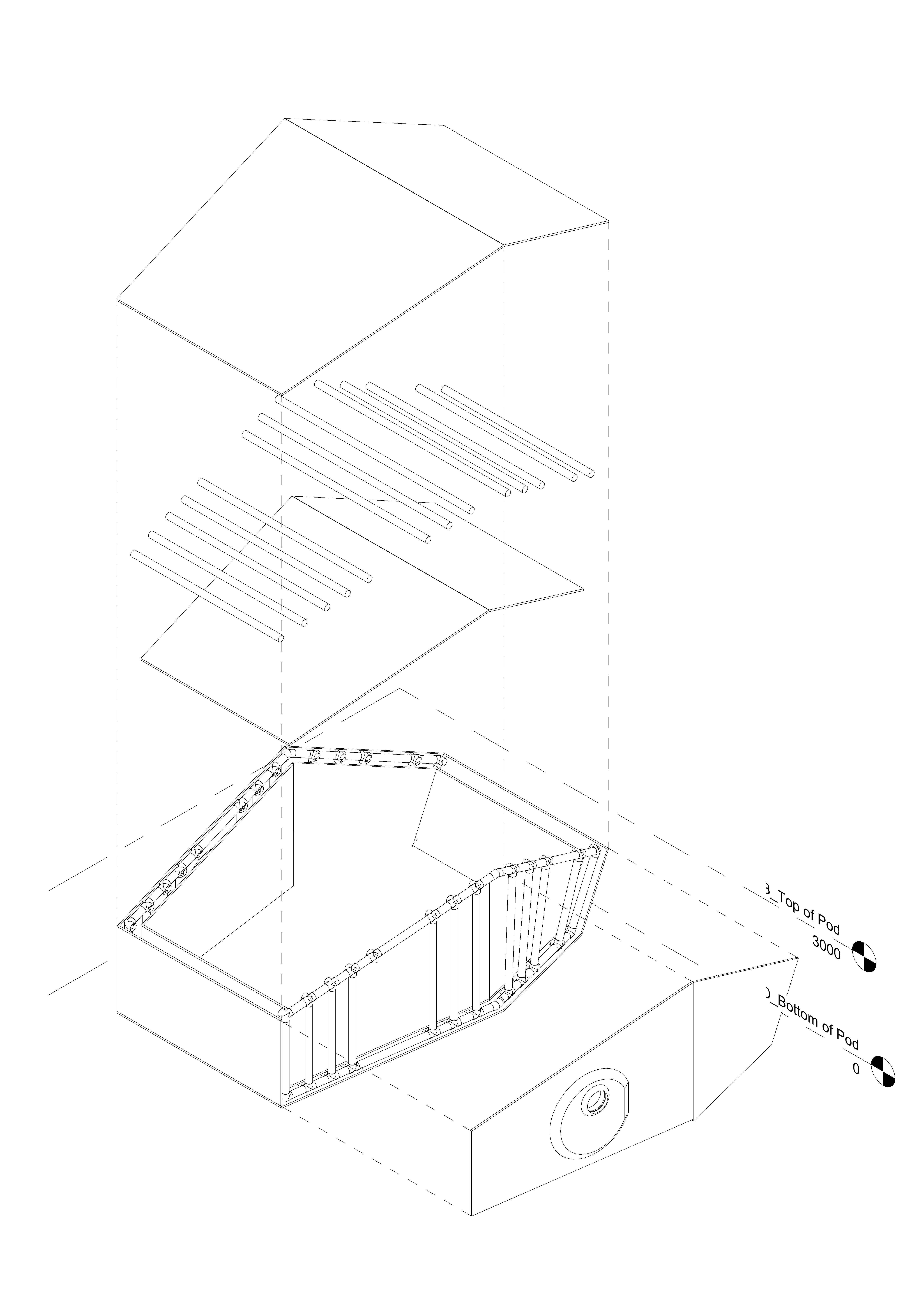
Pod in Revit
Documentation
Project Phasing
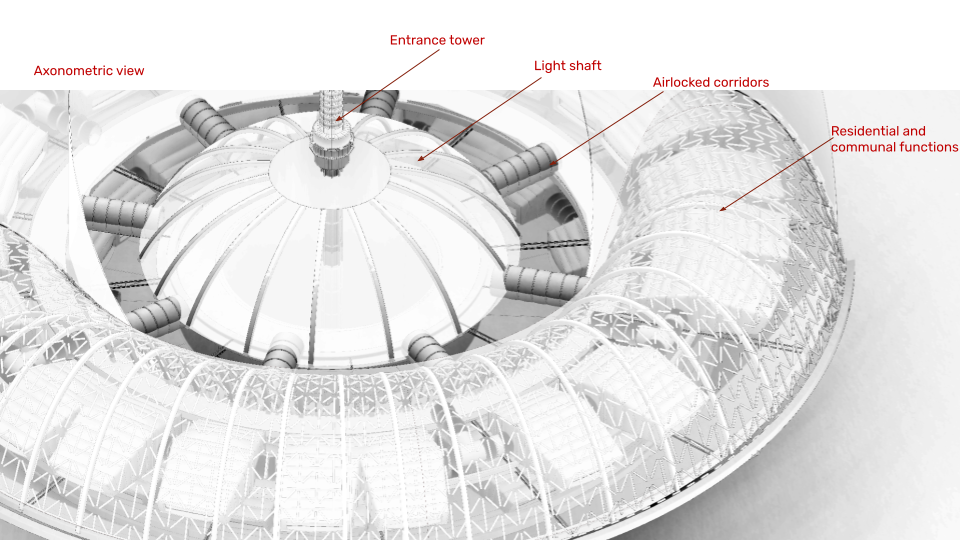
General Arrangement Drawings
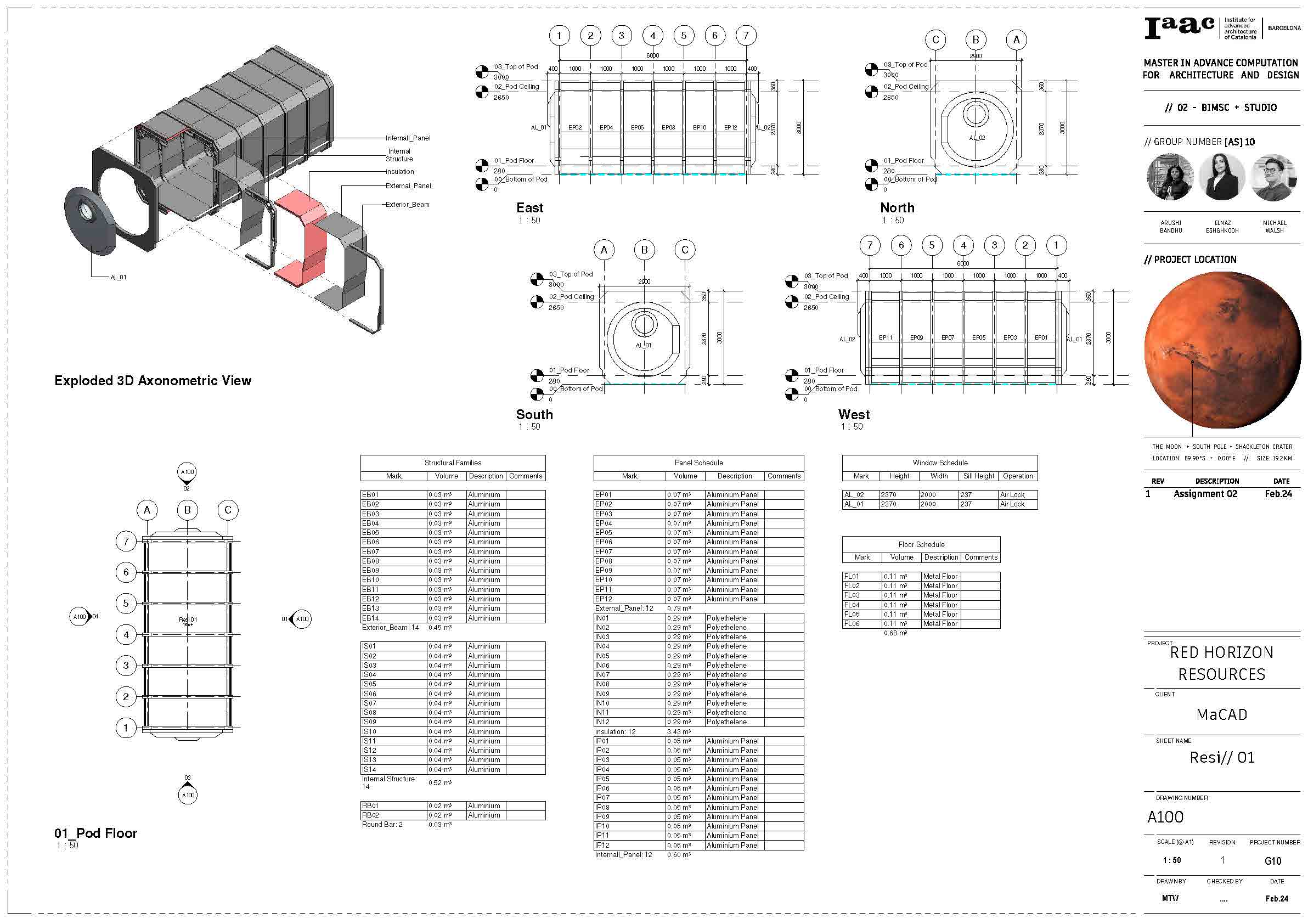
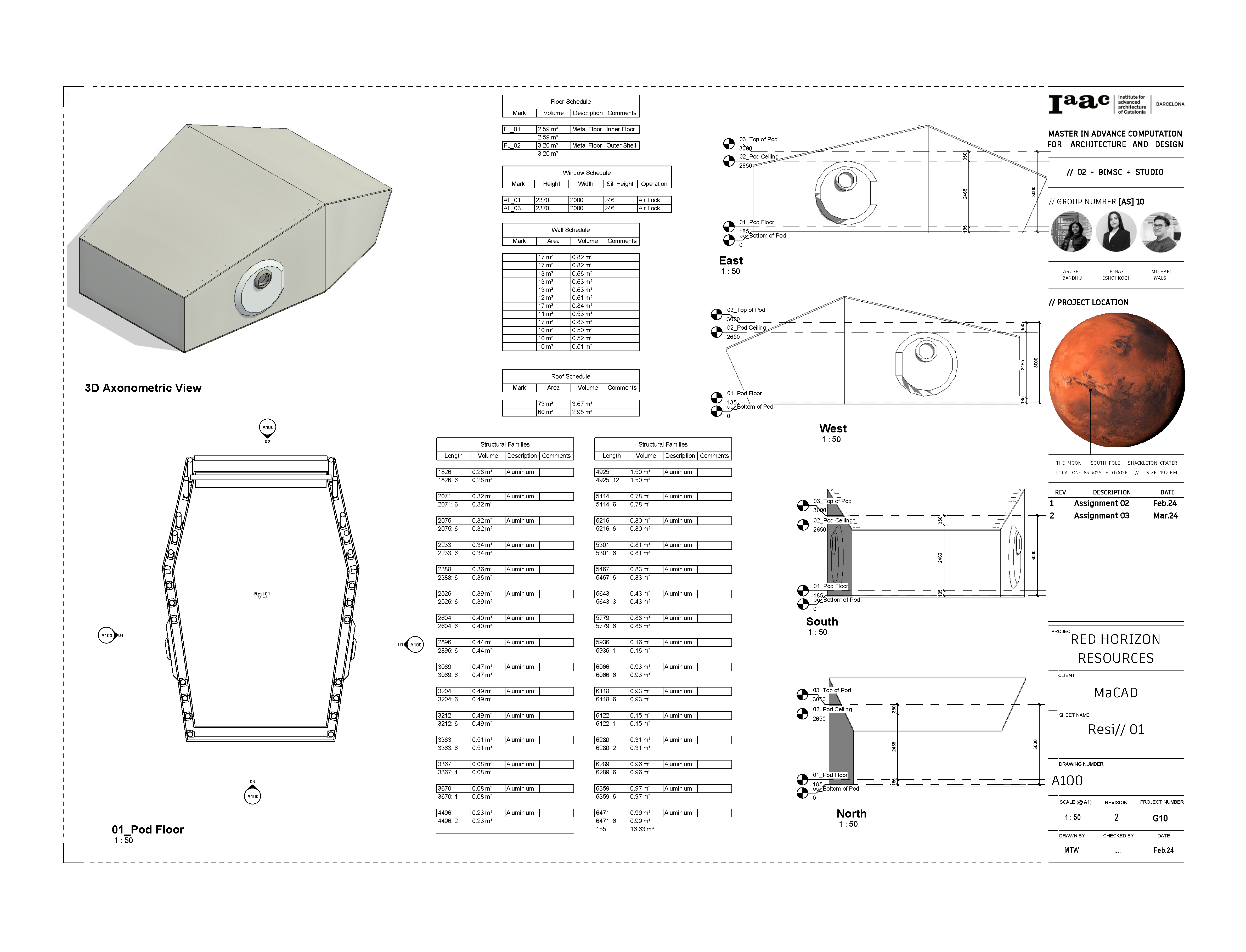
Axonometric + Schedules
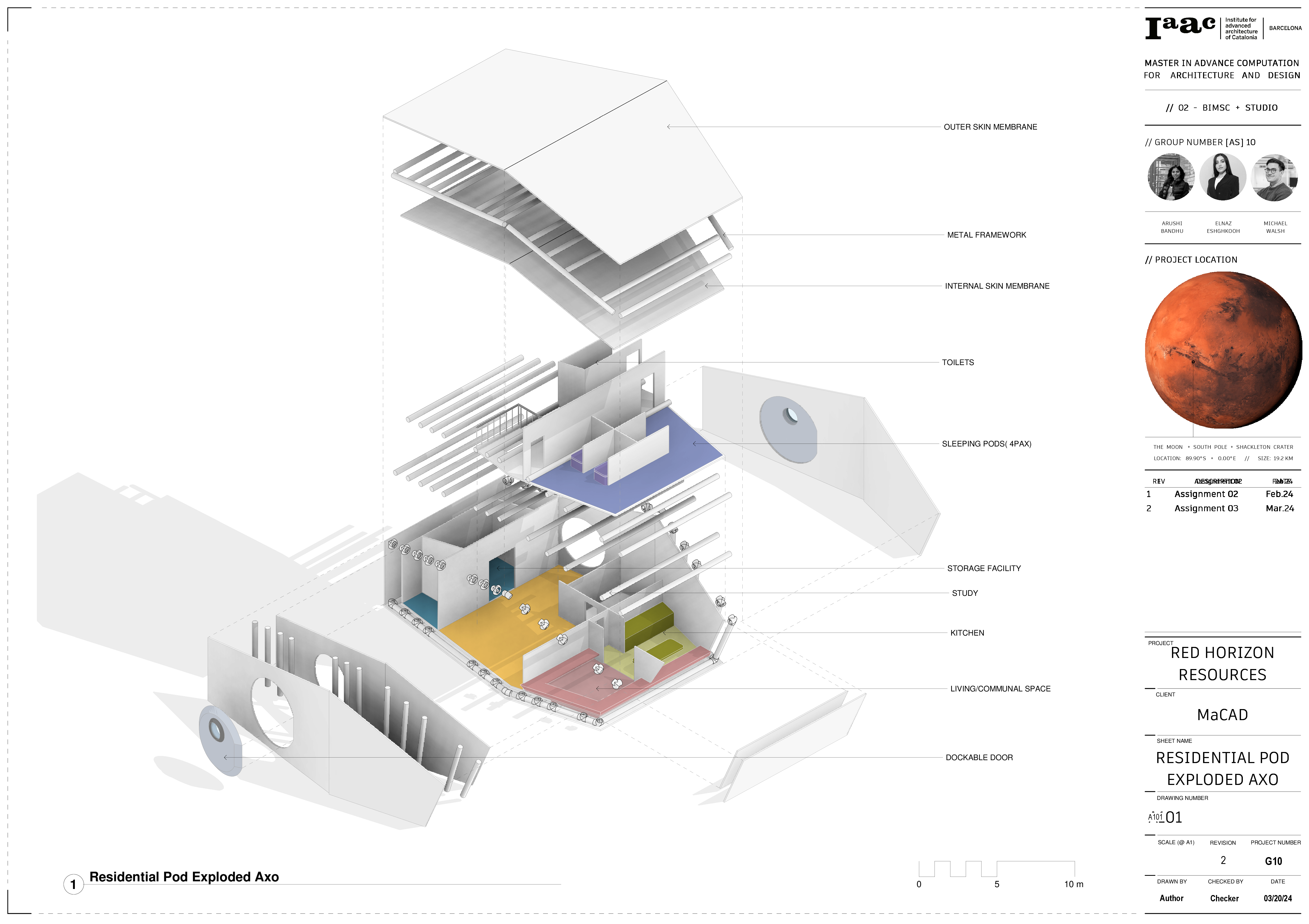
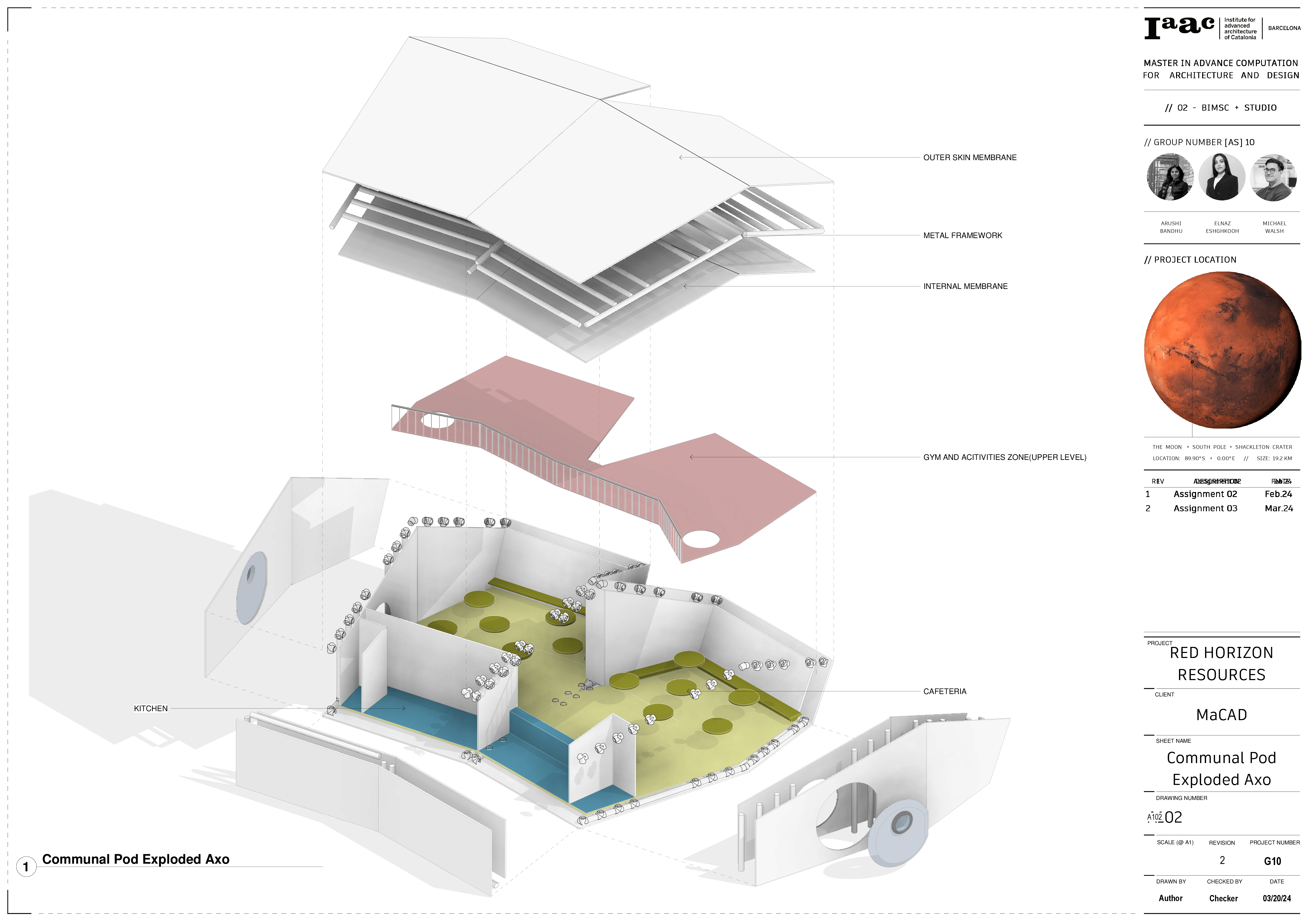
Pods
Render