Abstract
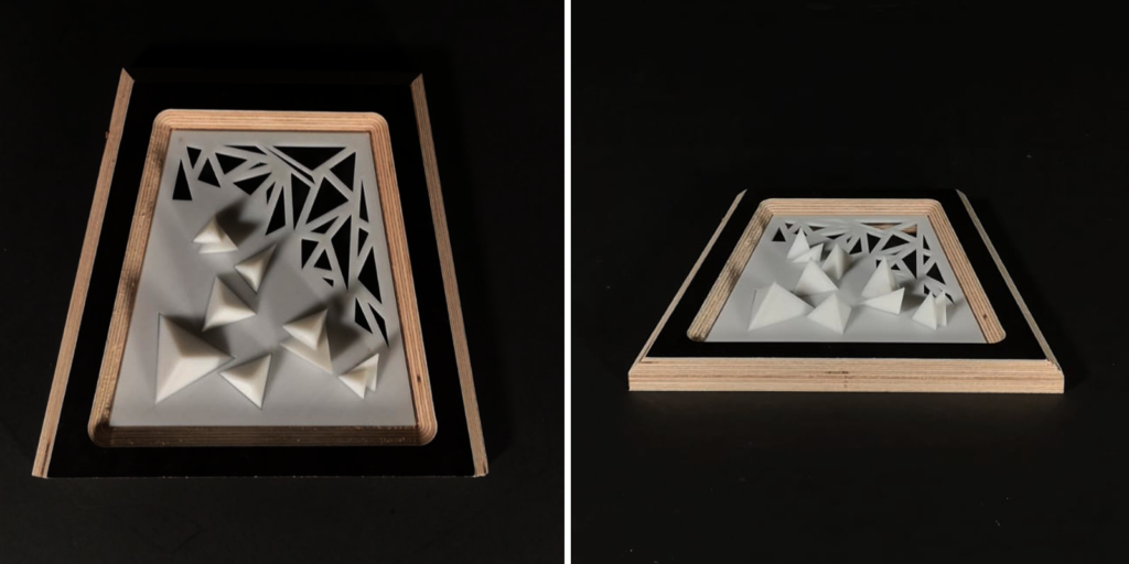
The introductory course on Digital Fabrication proposes exploring new production techniques through the relationship between computer data and machine-oriented fabrication. The final purpose was to acclimatize with the three most common digital fabrication processes: CNC milling, Laser Cutting, and 3D Printing.
Our personal exploration of these techniques is here disclosed with these three models, which summarise our experimentation with different materials, procedures, and programs, in order of creating a prototype for each technology that better explains the knowledge learned during the early manufacturing phase.
CNC Milling
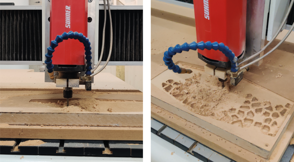
The manufacturing technique of CNC Milling consists of a Subtractive process, which indicates that the raw material is carved into the desired 3D shape by using a controlled material-removal process, divided into different steps.
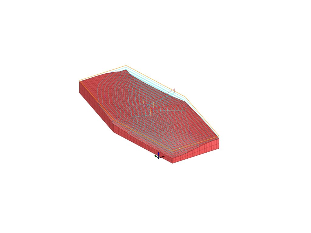
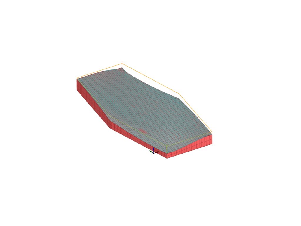
- Starting from the initial hexagonal volume, the first step was to dig down in the volume to subtract most excess material with Horizontal Roughing and smooth the curved surface with Parallel Finishing, both 3-axis operations.
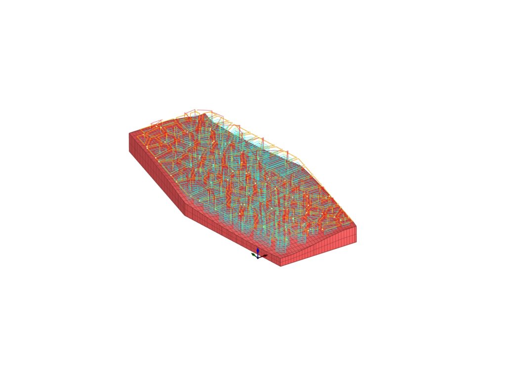
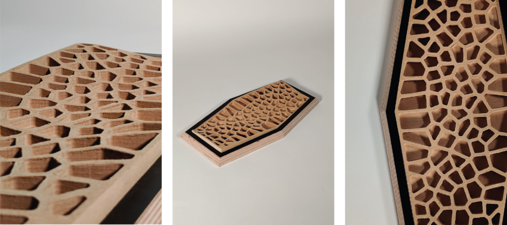
- The sculpted volume is now subjected to 2-axis operations: the closed vectors representing the geometry to be carved in the volume are used. The polygons in question were designed on the basis of the limits of the 6mm tip that was used for the Pocketing operation, which allowed us to dig down into the volume for a total of 20 mm.
- As the last operation, Profiling was used to free the hexagonal volume from the rectangular base from which it was obtained, keeping it tied to it through 4 bridges that were eliminated thanks to a chisel. The last steps were finishing the edges thanks to the sanding machine, in order to make the model the perfect size to enter the frame
Strategy and Parameters

Laser Cutting
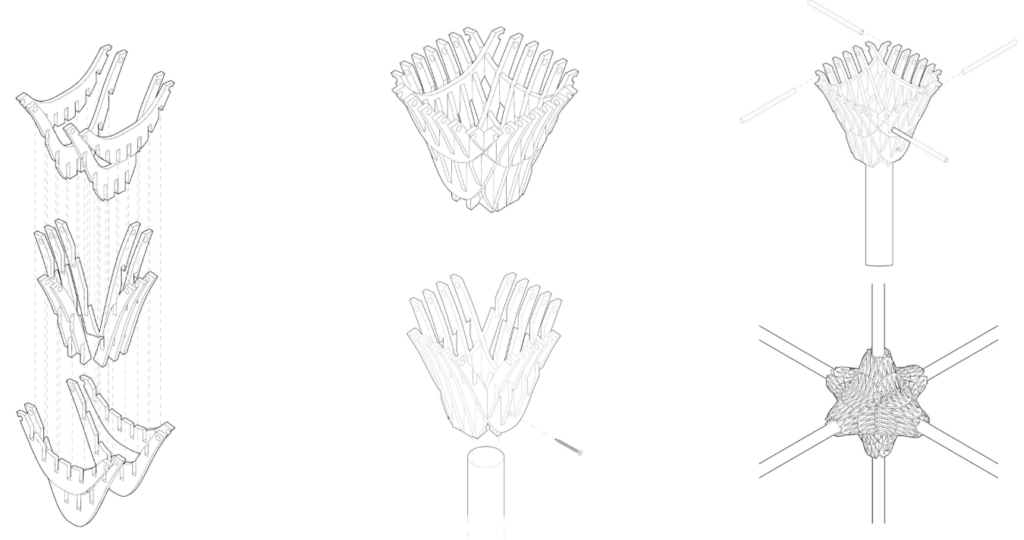
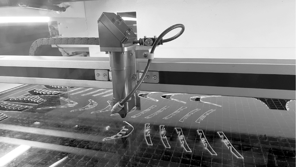
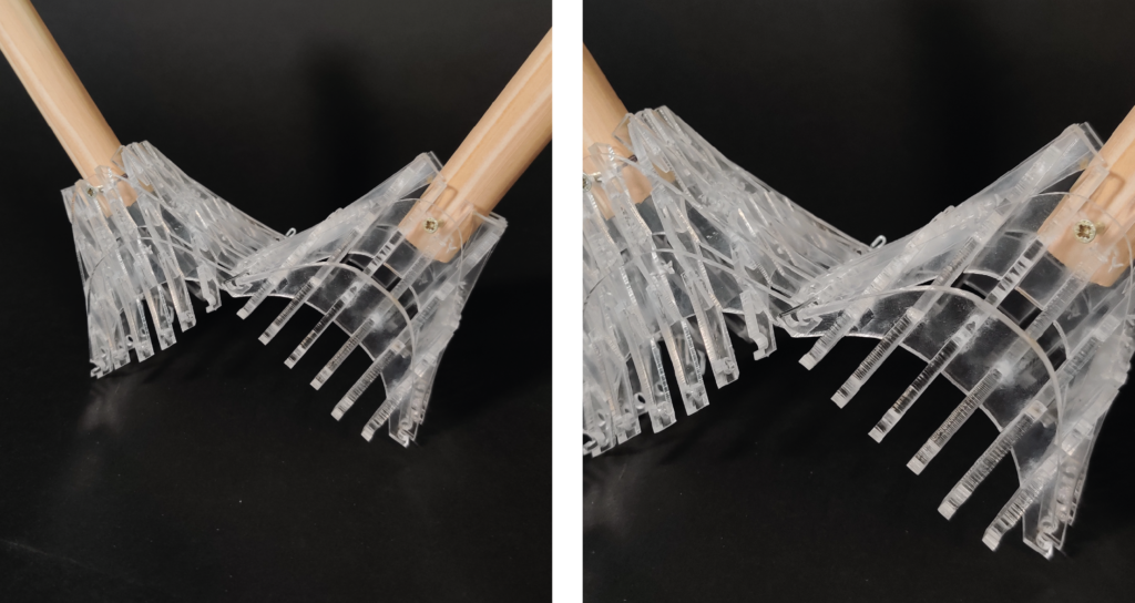
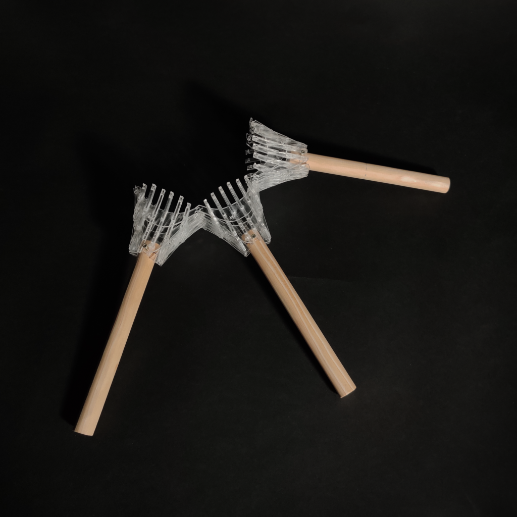
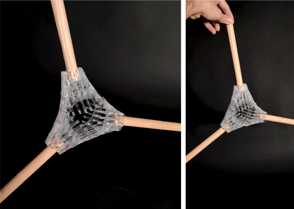
The technique we worked with was the waffle.
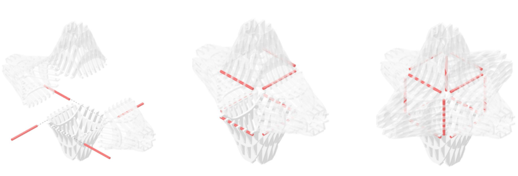
The idea that led to the concept of the model is the possibility of spatial aggregation. We realized a modular joint can allow spatial assemblage on several sides of the single module, following different degrees of inclination. The final result will be given by the union of every specific unit, each of which is to accommodate a beam. Connections are possible in every direction, making the final result able to accommodate multiple beams in accordance with the specific need.
Strategy and parameters
Material: Acrylic, 3mm
Technique: Laser Cutting
Joint type: Waffle Joint
Machine: Rayjet400 Laser cutter 60-100W
Working Parameters:
Power: 55
Speed: 2
Cutting time: 1.5h
Construction Diagram
3D Printing
Parameters and percentages of the perforated surface of the following model have been decided according to the time limits for the exercise in question.
3D printing is a technique that works by aggregation of material, which in this case corresponded to a white filament of Z-ABS.
Strategy and parameters
Printer: Zortrax M200
Material: Z-ABS
Nozzle diameter: 0.4mm
Support: 20°
Layer: 0.19mm
Infill: 20%
Raft: Enabled
Material Usage: 18.83m (45g)
Print Time: 4h 53m
