
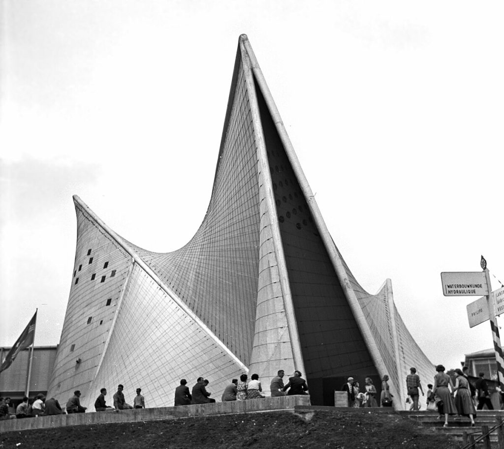
The Philips Pavilion was a groundbreaking synthesis of architecture, visual media, and music, showcasing Philips’ diverse technologies, from sound production to X-ray lighting. Unlike traditional product displays, the pavilion itself became an exhibition, highlighting all that Philips had to offer.
Architect Le Corbusier -Iannis Xenakis
Structural Engineer Hoyte Duyster
Developer Philips
Built in 1958
Location Brussels, Belgium
THE CONCEPT
The basic guidelines were that the interior would be similar to the stomach of a cow, with the resulting basic form of a mathematical algorithm form.
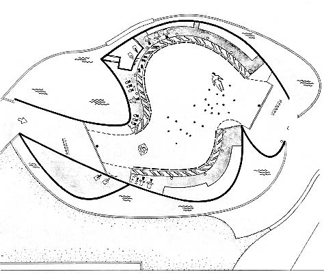
Visitors entered the Philips Pavilion in groups of 500 at 10-minute intervals. For the first 2 minutes in the curved hallway, they experienced a transition piece composed by Xenakis. Subsequently, for 8 minutes in a darkened room, they were enveloped in a space of light, sound, and visual images along the pavilion walls. At the end of the projection 8 minutes would leave viewers ”digested” through another exit, while entering the next group.
THE STRUCTURAL PRINCIPLE
The structure features curved hyperbolic paraboloid planes, generated mathematically from straight lines. Xenakis’ proposals included sloping walls to fulfill Le Corbusier’s vision of irregular warped surfaces for image projection.
The geometry not only satisfied Le Corbusier’s desire for mathematical rationality but also incorporated expressive slopes and contours, creating an expressionistic language.
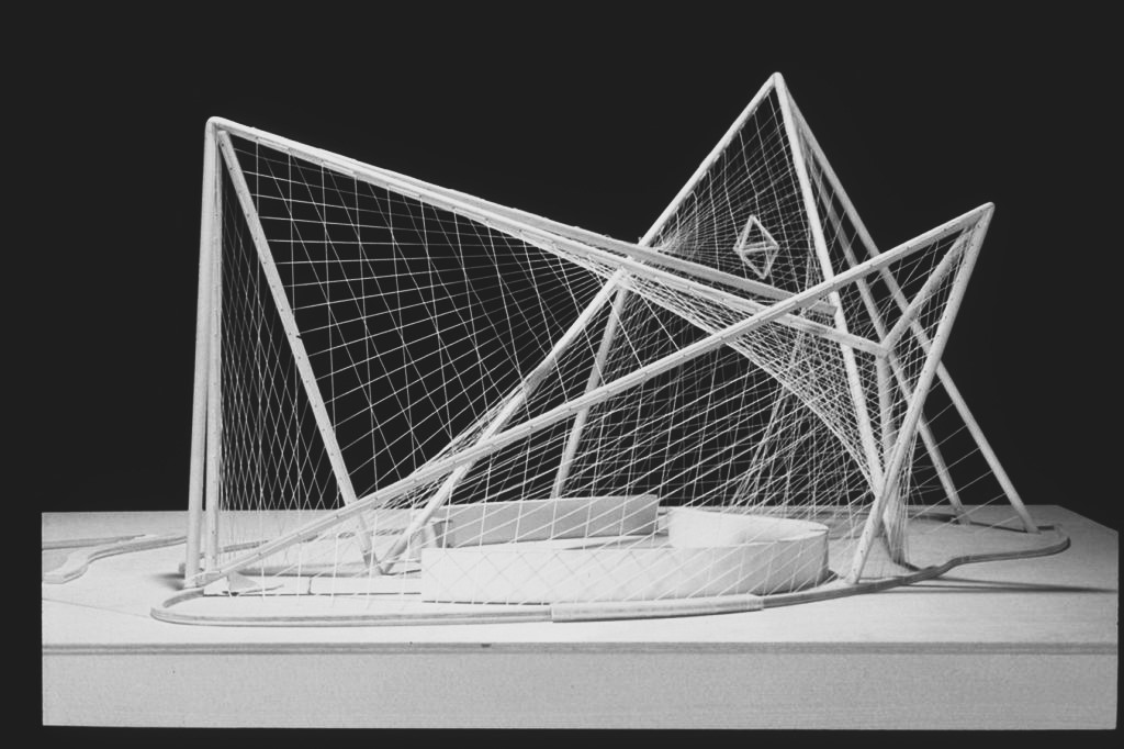
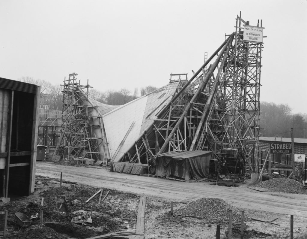
The structure employs a combination of steel and reinforced concrete, utilizing a system of prestressing steel attached to concrete supports, with thin precast panels covering spaces between them. Steel masts and cables at the ends provide additional support.

The complex shapes of the structure made conventional poured concrete unfeasible, leading Xenakis and engineer Hoyte Duyster to devise a system of prefabricated concrete panels suspended by tensioned steel cables. This solution aligned well with the generation of hyperbolic paraboloids through straight lines, making prefabricated panels easily implementable.
The coating material texture can be adjusted based on the movement of hyperbolic forms, following a simple mathematical equation and the hanging of three points of the tent enclosing the pavilion.
PLANS OF THE PAVILION
SCRIPT

The script is divided into specific steps needed to create this pavilion in Grasshopper. Beginning with the basic geometries, the base and the peak points to later on creating the surfaces and the tiles-panels. Finally, setting up the camera and the animation.
PSEUDOCODE
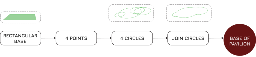
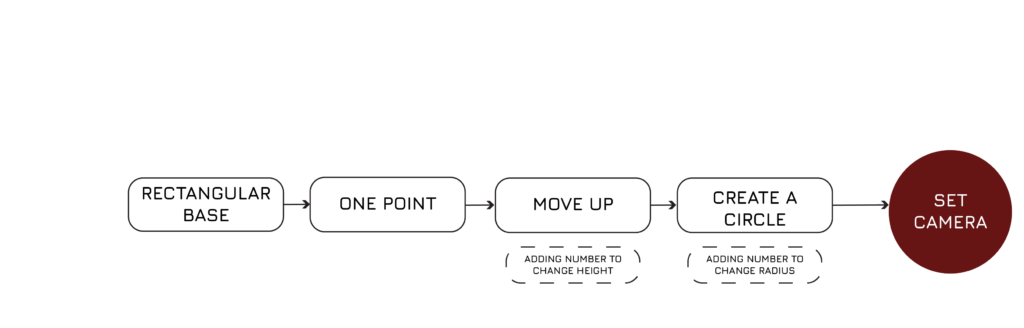
BASE CREATION
PEAK POINTS CREATION

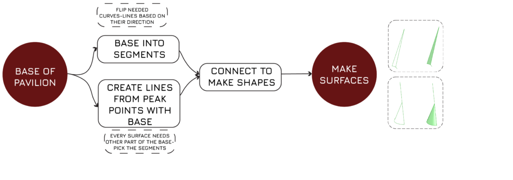
SURFACE CREATION
This logic was used to create all of the surfaces (6), with minor differentiations, like joining curves, flipping curves, changing surface components (patch, ruled surface, sweep1-2) e.t.c.
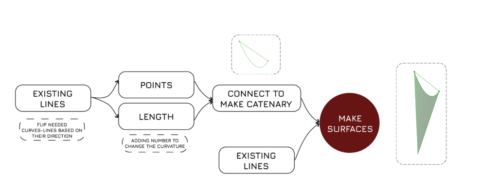
UPPER SURFACE CREATION
This logic was used to create all of the upper surfaces (3), with minor differentiations.
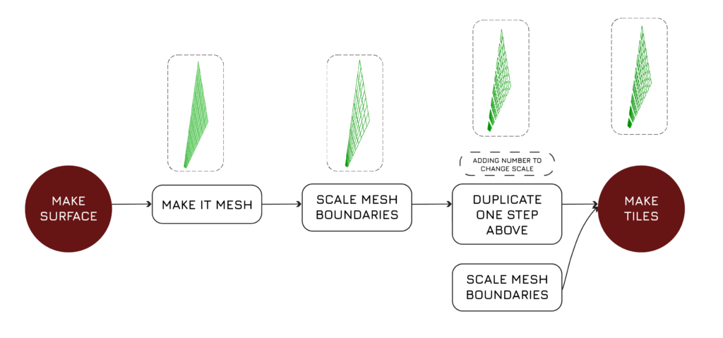
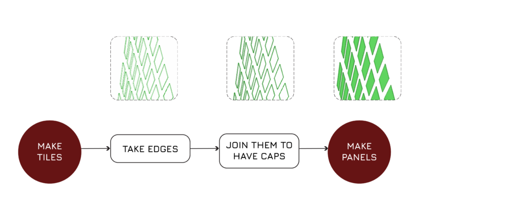
TILE CREATION
This logic was used in all the 11 surfaces to create the tiles.
PANEL CREATION
This logic was used in all the 11 surfaces to create the panels from the tiles previously made.
CAMERA SETUP
ANIMATION
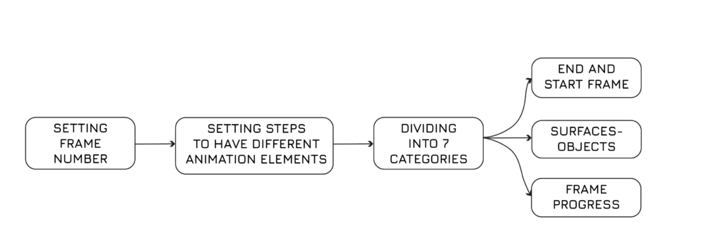

ANIMATION
Camera setup 1
- LINES
- PIPES
- SURFACES
- TILES
- PANELS
- CHANGE HEIGHT OF POINT 1
- CHANGE HEIGHT OF PONT 2

Camera setup 2
- LINES
- PIPES
- SURFACES
- TILES
- PANELS
- CHANGE HEIGHT OF POINT 1
- CHANGE HEIGHT OF PONT 2

RENDERS OF ANIMATION PROCESS


