The brief for the BIM & Smart Construction studio module tasked us with developing an outpost on Mars whilst collaborating with the wider cohort to eventually develop a colony. We were given a number of potential directives to choose from, of which we chose to look at mining and accommodation.
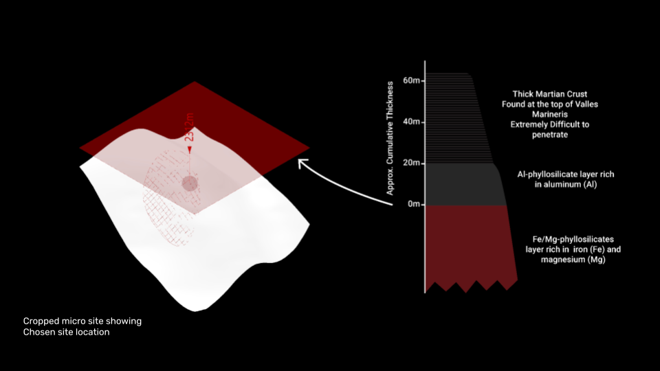
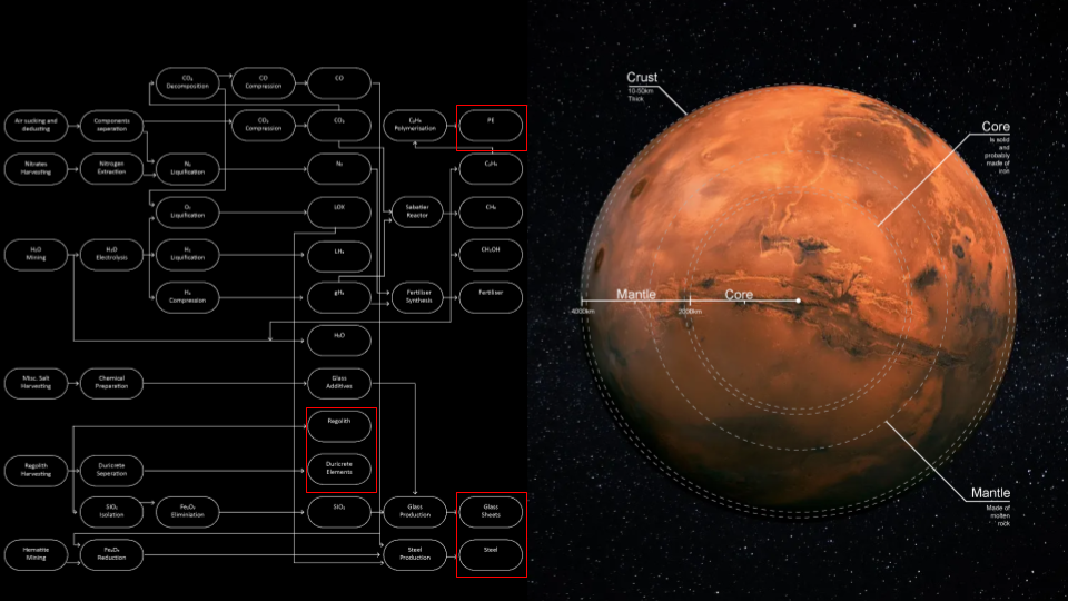
One of the first tasks set for the project was to choose a site. Initial research had shown us that anywhere 60m below the Martian surface would allow us to avoid the crust and allow access to resources rich layers below. As our site would be located with the trench of the Valles Marineris, we would be well below this line (as shown in the diagram) and so we could place ourselves in any position.
As part of the project, we were asked to develop an adaption approach. Our design intent was to develop a scheme of cliff dwellings – semi submerged structures which would cascade down the slopes of the trench. This would provide the structures with some protection from the solar radiation and reduce the need to produce material for structures. A site selection tool was developed which worked by grouping points based on the topographic level and then selecting sites within each group.
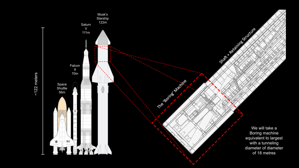
Research into conditions on Mars revealed an incredibly tough surface which could pose some issues for mining. Therefor we propose to take a boring machine from Earth which could be used to puncture through the Martian sediment. The size of this machine would be determined by the vessel which would be carrying our pilgrims to Mars; the largest possible of which being Space X’s Starship. Therefor the maximum diameter available to use would be 18m to allow us to fit it within the cargo hold.
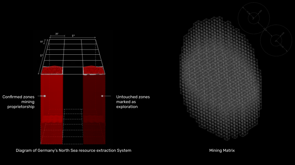
The dimensions of the boring machine would then dictate the rules for the project zoning and setting out. Reference was made to the licensing blocks within the North sea in order to organise exploration and organisation of the system. We had developed a mining matrix below the surface of our site which would work using 50m3 voxels – this would allow for structural integrity of the shafts should they be positioned near each other.
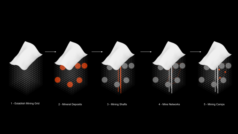
The anticipated computational design approach would therefor organise itself across 5 stages; establishing the matrix, generating speculative mineral deposits, locating the mining shafts based on the sites, developing the networks between the shafts and their connections and then finally looking at the mining camps – which were initially proposed to be mostly subterranean.
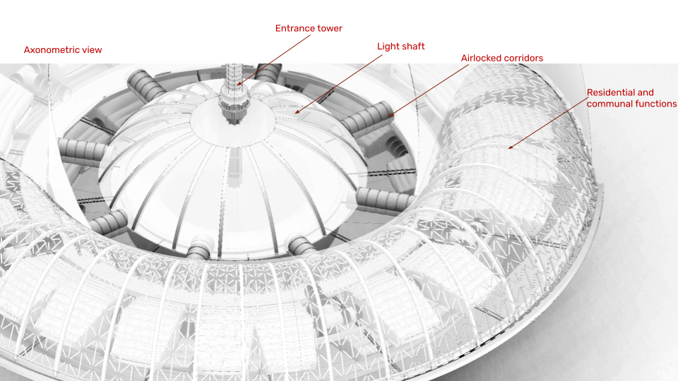
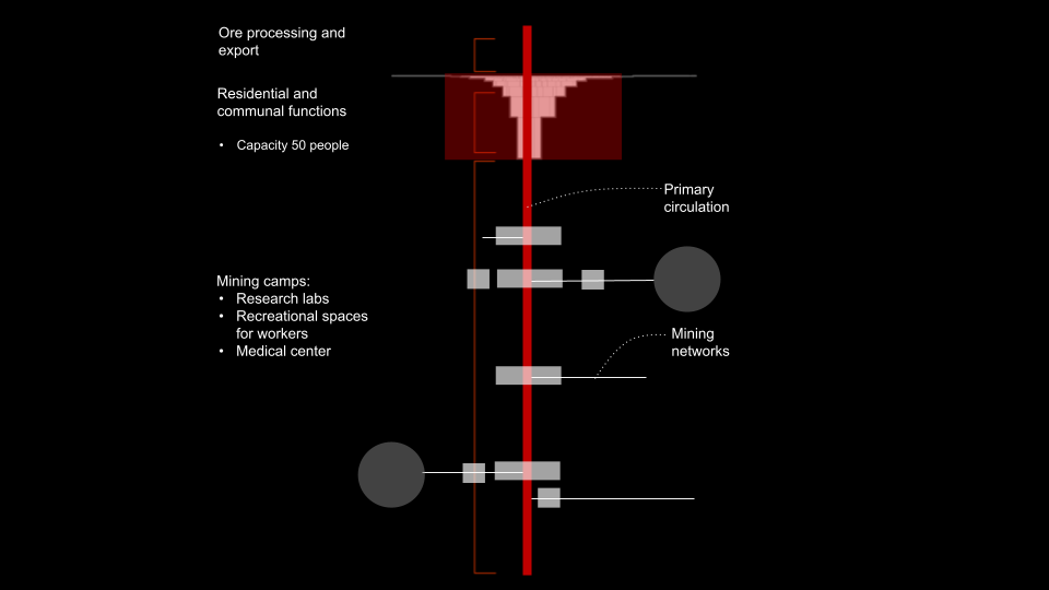
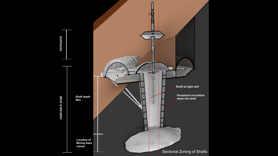
Initially we had looked at organising our section into different zones; A residential zone with accommodation and communal functions at the surface, Vertical circulation cores and then incremental mining networks and mining camps off of these cores.
In order to test our initial assumptions of organisation and decide on the placement of the mining camps, we decided to test the site positions and the depth of the shafts for daylight using a combination of ladybug and Galapagos. From this we found that the maximum depth our camps could sit at and still receive sunlight would be 50m. This ultimately led to us adjusting our approach to the design of the system.
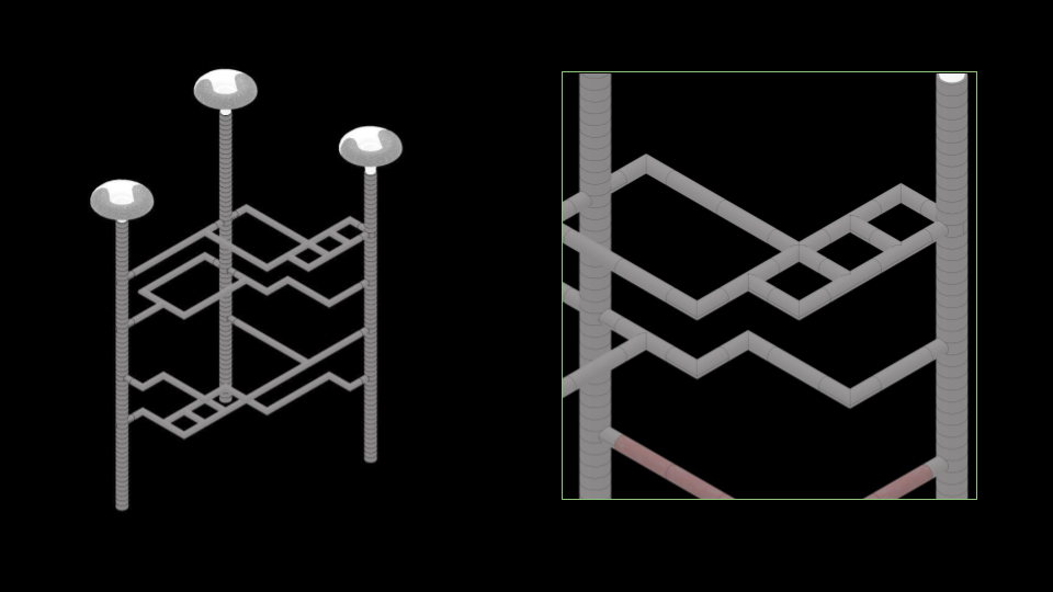
We then looked into how we could organise the horizontal connections. First we would establish the vertical cores down from the sites to highlight voxels within the matrix. We would then look to match the Z positions in the cores, allowing for 100m different so that the tunnels did not interfere with each other. These voxels would then be used as start and end points for the desired paths moving forward.
As our project is looking at mining but there is limited information as to how minerals are formed on Mars, we decided to speculatively generate deposits within the matrix based on research. We would then use this research to influence how the paths were formed.

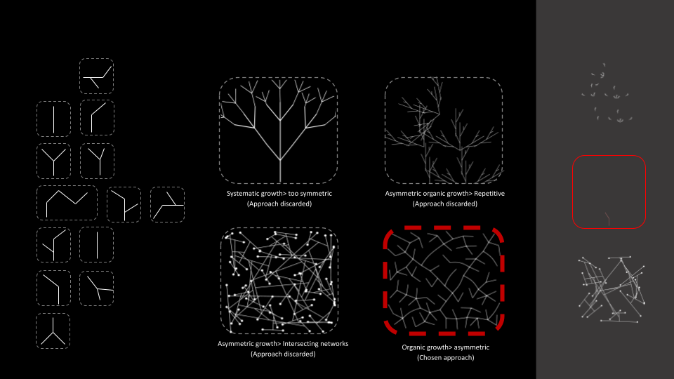
Originally, we considered utilising a stochastic aggregation system to formulate the paths. However, we discovered that the outcomes were less manageable and presented greater difficulty in handling than anticipated.
We then moved to looking at a type of search algorithm called Dijkstra’s algorithm – this is a method used in computer science to find the shortest path between two points in a graph. It’s named after Edsger W. Dijkstra, a Dutch computer scientist who developed it in 1956. Imagine you’re in a city with many streets connecting different locations, and you want to find the shortest route from your current location to a destination. Dijkstra’s algorithm helps you do just that. This would would work well with the matrix and allow us to find the shortest path between nodes.
Example taken from: https://ivanstajcer.medium.com/how-dijkstras-algorithm-works-with-visual-example-32b73722406a
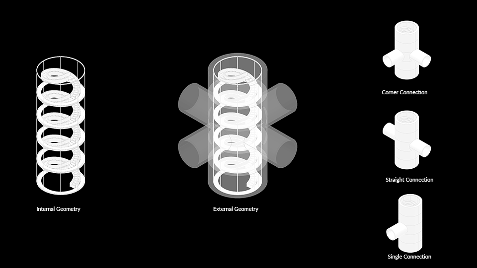
In order to understand the amount of material needed to construct these mine paths, we looked to assign geometry types to voxels within the natrix based on their connections. We developed a custom grasshopper definition which would allow the design of these connections to flex with the dimensions of the matrix if needed.
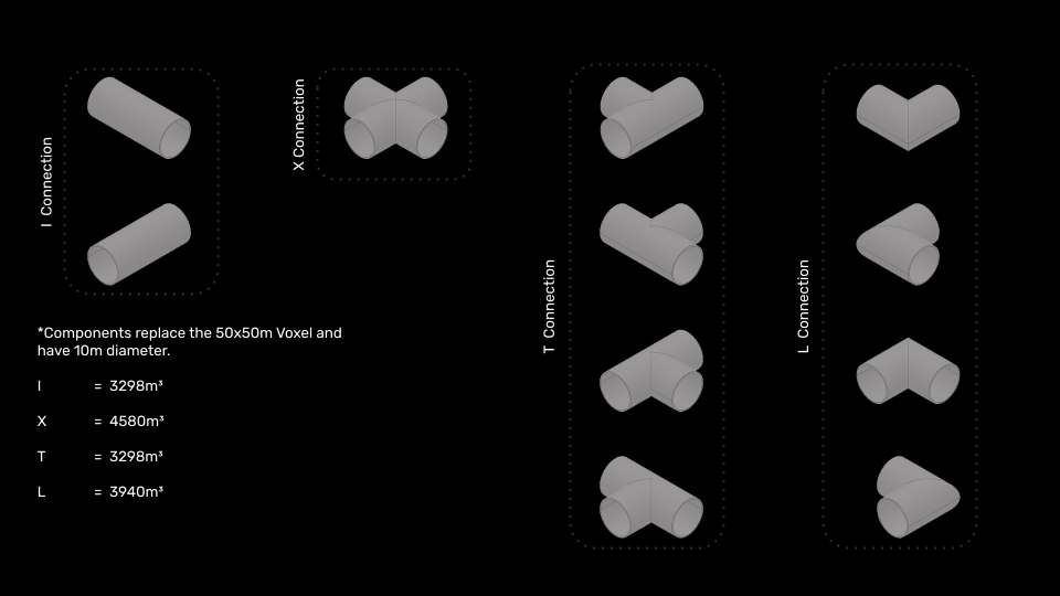
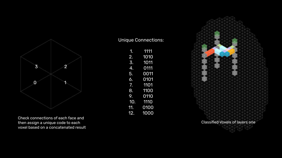
Based on the connections of the grid, a custom identifier code would be assigned to the voxel which would then allow us to move the geometry into place with our automation tool.
The same method was also used to provide the geometry for the vertical shafts and connections.
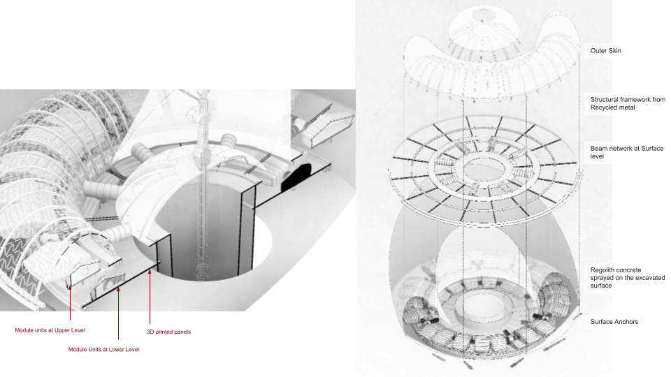
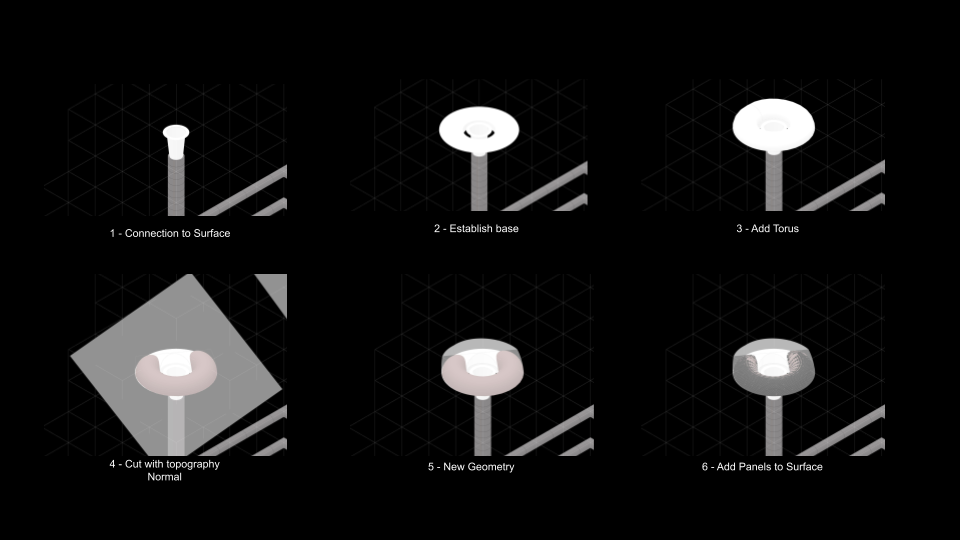
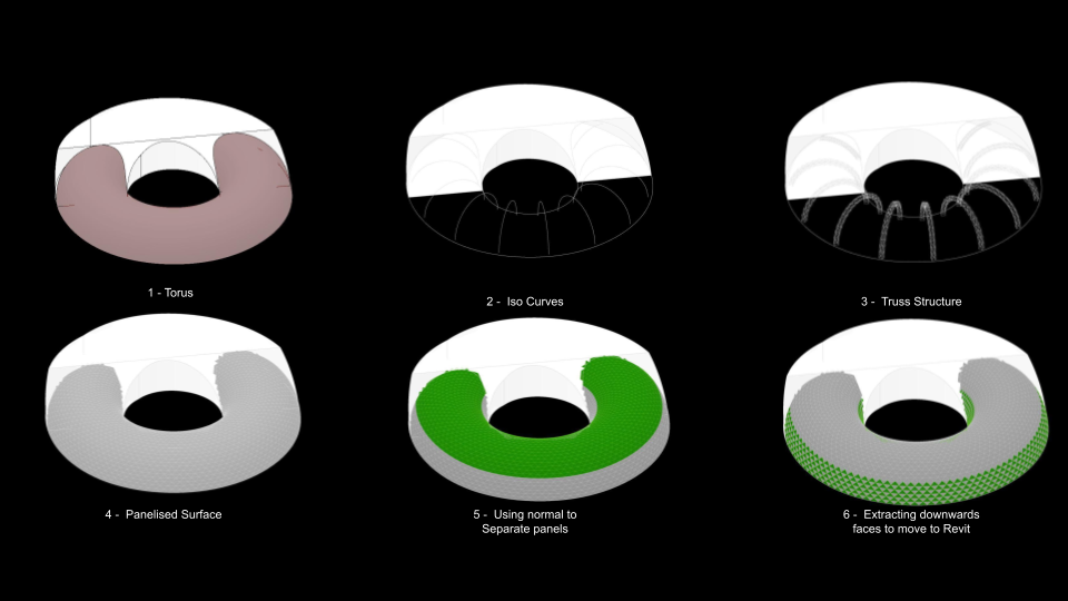
The definitions then examined our approach to handling surface connections. We devised a connection of variable height that linked the shaft to the base of the surface zone. Opting for torus geometry was motivated by its advantageous surface-to-volume ratio. Subsequently, we explored segmenting this geometry using the site mesh. This segmentation process allowed us to identify which part of the geometry was submerged and what measures would be necessary to counteract the effects of radiation. Next, a panel system was applied to the external section of the torus, offering a platform for testing and further refinement.
The definition allowed for a high degree of flexibility, allowing us to move sites seamlessly. In this way it was easy for us to decide on the phasing of the scheme. The concept was to start near the top of our site and cascade down over time.
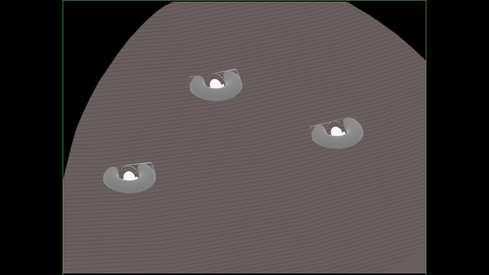
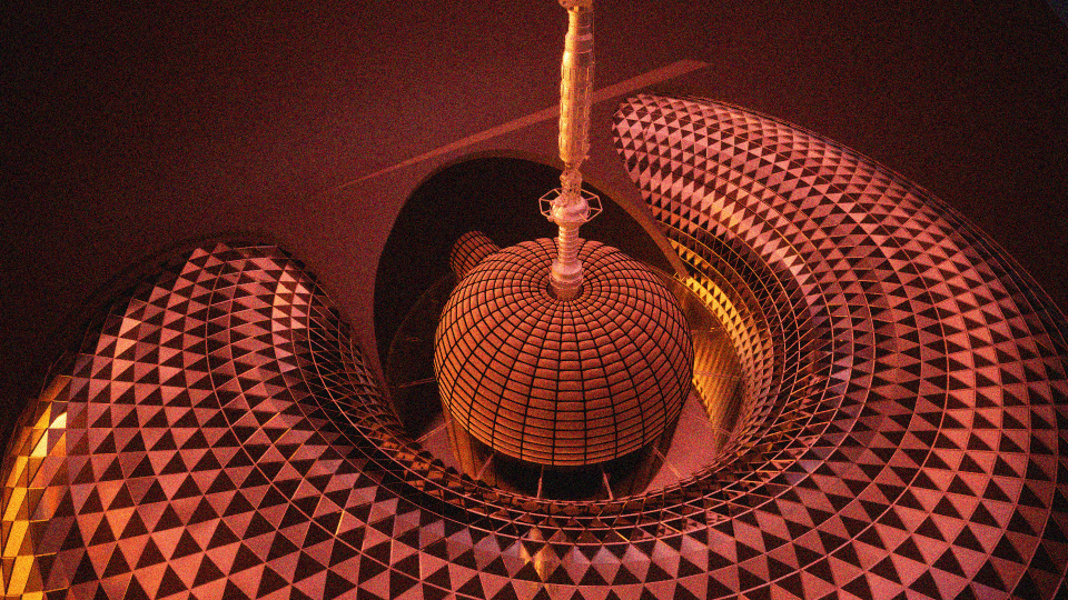
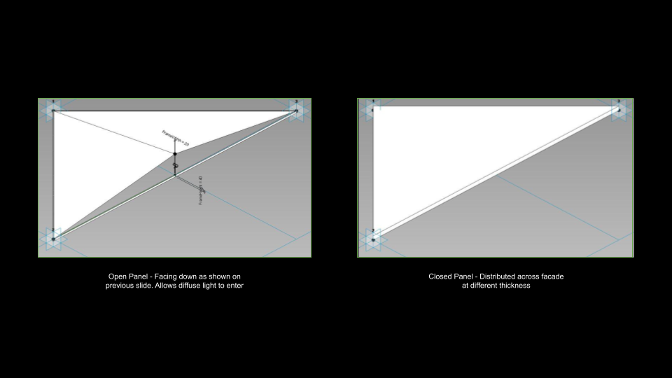
As discussed, the external part of the torus required development in order to mitigate the harmful effects of the radiation. We also looked to develop structure based on the iso curves. The panelisation was then split using the surface normals. We then specially looked for the panels which were facing down to work with our custom panel families within Revit.
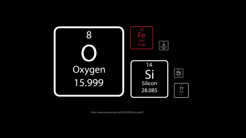
As part of our concept, we conducted research into what materials would be available on arrival and what we might have access to with time. This would then inform the design of our project.
Based on the daylighting research, we then looked to further develop the surface zone and its connection with the mining networks.
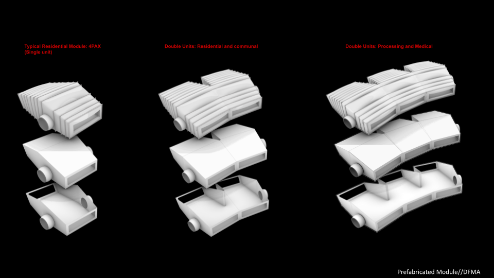
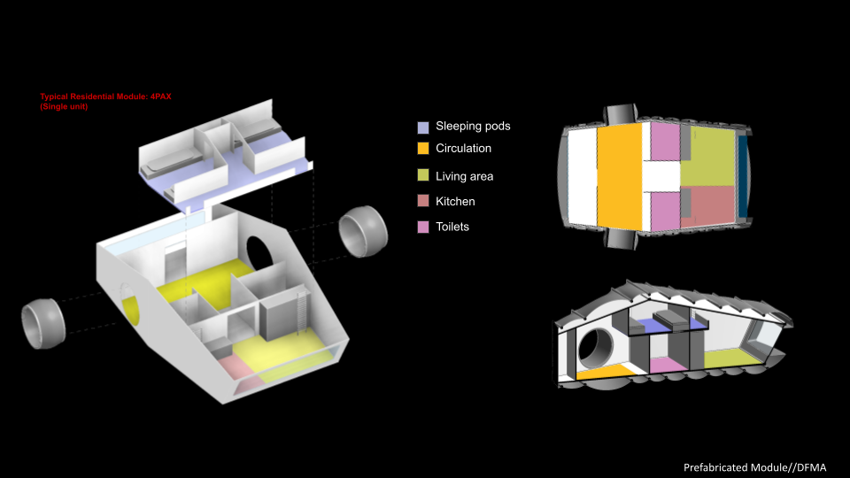
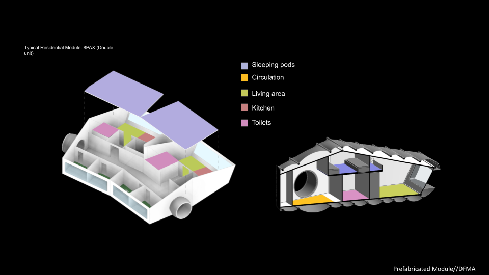
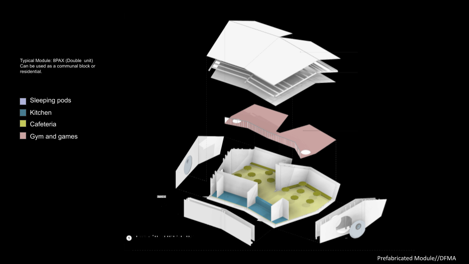
Pods were designed in a way that they could be modular and the same kit of part could be applied to the design of the units. A number of different unit types were designed to accommodate the need of the outpost.
The detail of the surface zone was then developed using grasshopper to provide a more tangible outlook of what might be required to construct the structure.