
Context
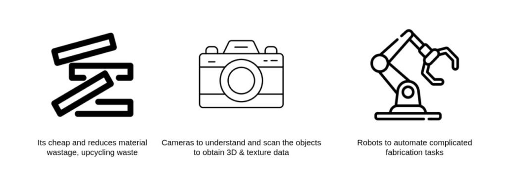
This blog documents the negotiation of a System of Scan to Fabricate workflows related to dealing with irregular raw materials, Namely offcuts from the saw-mill logging industry and
CNC – Offcuts in the digital fabrication workshop.
A negotiation between design input and the raw material topology necessitates research.
With each material presenting unique Opportunities and Challenges in
a)The Design Space
b) Digital fabrication
c) Data management system.
Design – Process
A top down approach of sending objects into Space.
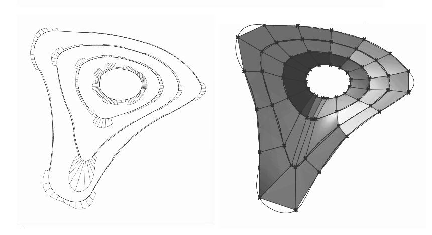
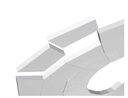
A canopy – Sub-D to Quad meshes – understanding surface geometry and Mesh Subdivisions.
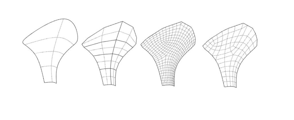
A Design control to Nest objects or control the Size of the segments.
Selected Material- Prototype 1
Design to Fabrication Idea – 1.1
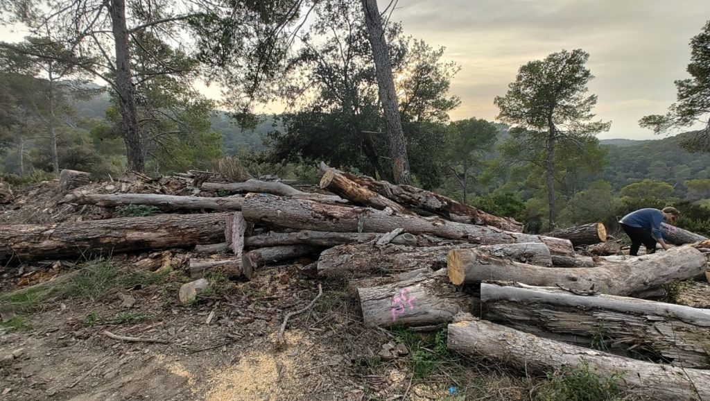
Offcuts from the sawmill industry , i.e. which can be processed into plain sawn logs for our purposes.
Scan – Photogrammetry
Scan to Cuts Generation
Prototype – 1.0
Design to Fabrication Idea – I
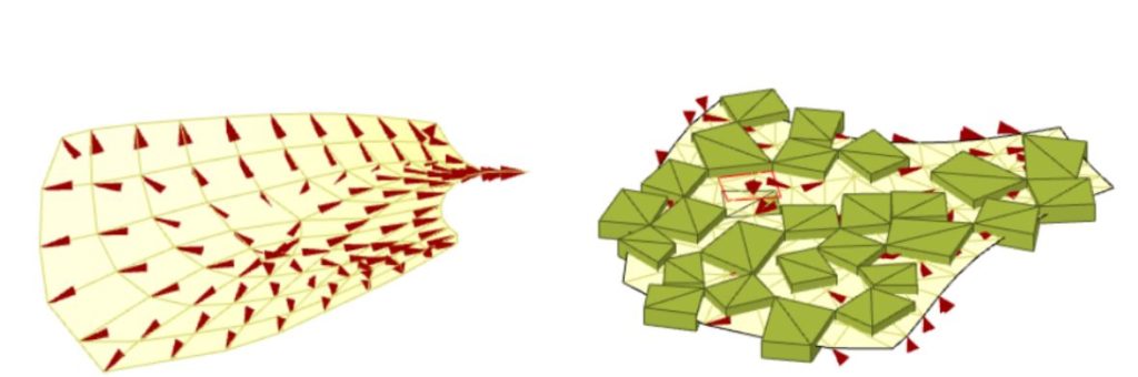
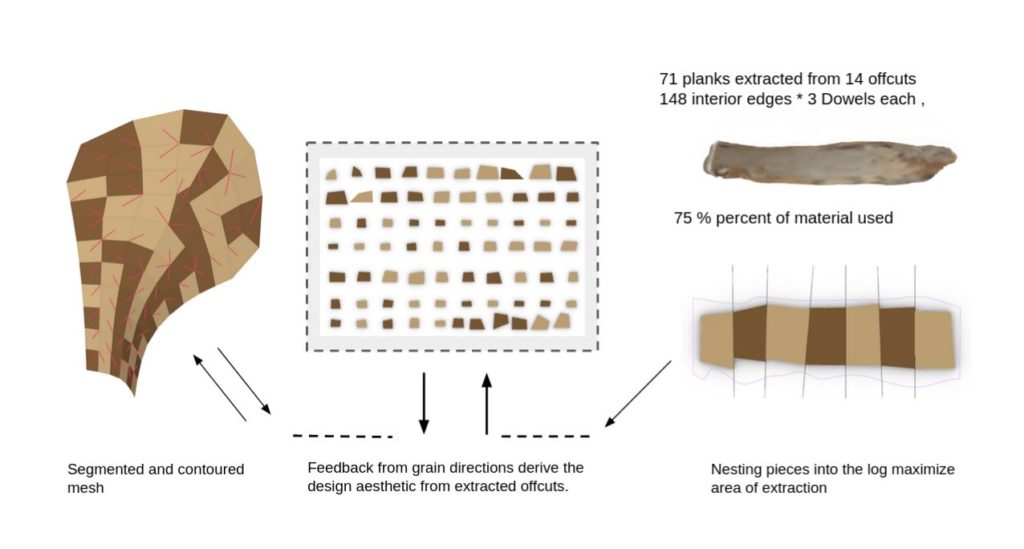
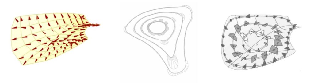
Distance heat method to segment meshes
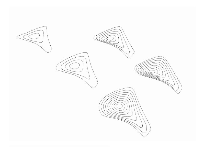
Segmenting/contouring meshes according to curvature
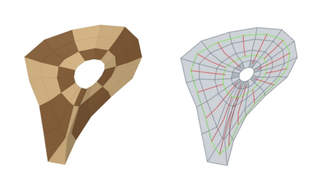
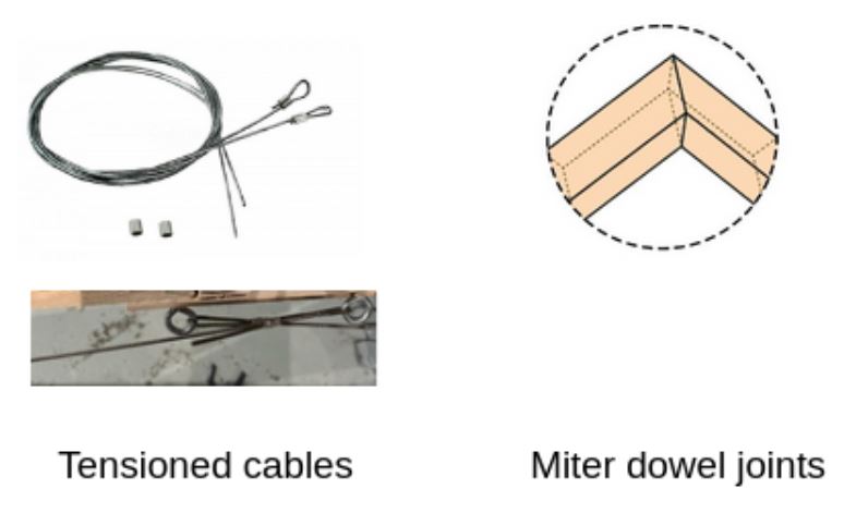
80 interior edges * 3 Dowels each
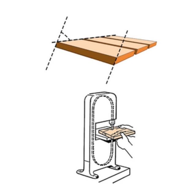
Nesting Segments in Planks
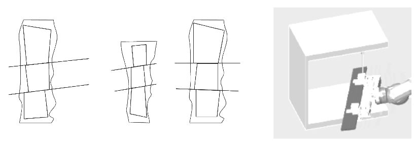
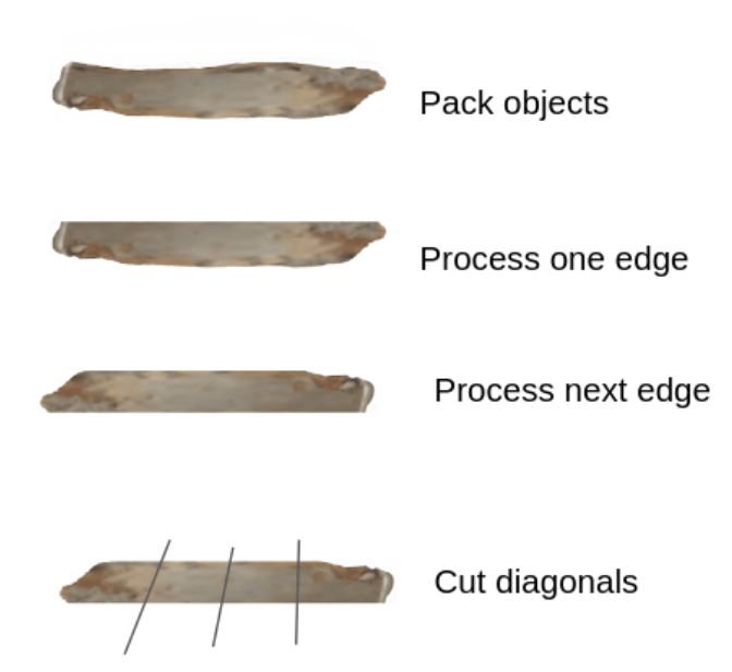
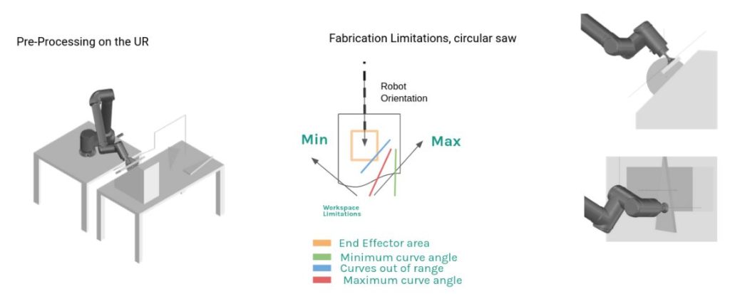
30 – 60 Horizontal angle limits
Cut diagonals
Robotic Simulation
Considered Robotic Processing tools
- Bandsaw
- Milling
- Circular saw
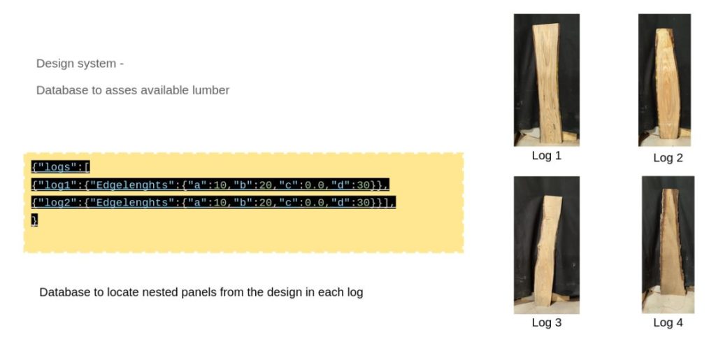
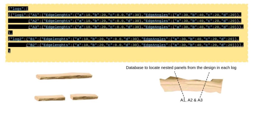
Design to Assembly – Database
The documentation of the logs to assist Robotic Fabrication.
The following data are recorded in a .json file for ease of information exchange between software platforms.
A Triangulated Framework to support panels
Design exploration of a framework for the panels.
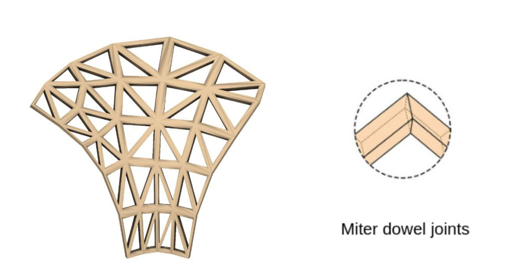
Reasons to avoid – Produces too much waste in production.
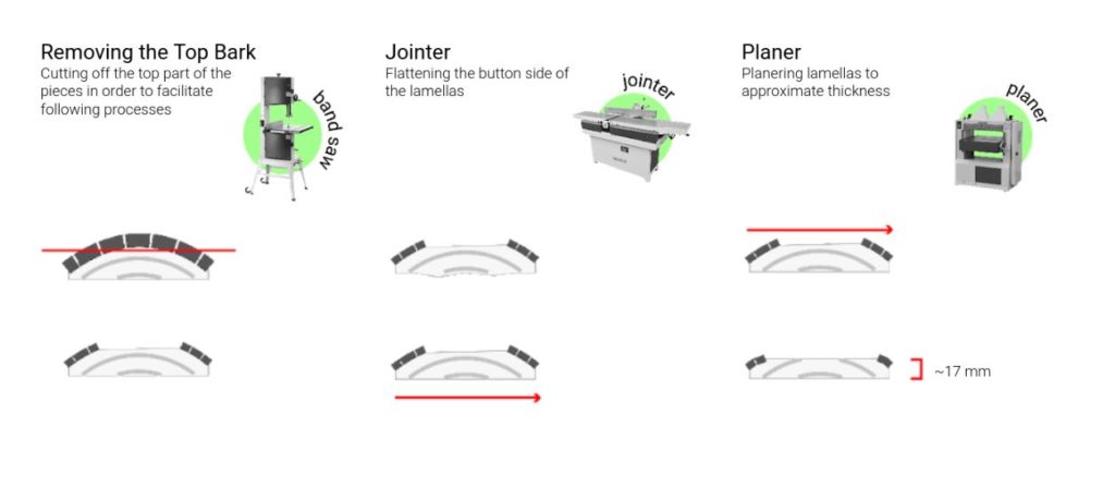
Production plan –
Planarise all logs – 5 min each , 10 logs.
Bandsaw:
Cuts on the bandsaw – 35
Cut length on the saw
Maximum 0.72m
Minimum 0.15m
- 2 min (500 mm/min)
- 1 typical cut = 2m = 4 min
Total edge travel of curves – 45.1 meters
Cut length on the bandsaw – 22.5 meters
Dowelling:
Edges joining – 84 * 3 Dowels
Finishing and extraction by Milling
Milling edge and depth reduced
1 m of milling = 0.3 min (3000 mm/min)
Design to Fabrication Idea – II
Material – CNC off-cuts
CNC Offcuts – Secondary Waste
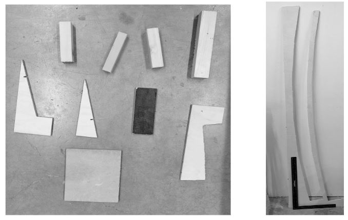
Description: Large – leftover blanks in the stock from CNC milling & Small – offcuts Milled around
References of similar projects:
1 Still Alive
2 Robotic Mosaic
Processing pieces into the dimensions of the planar surface:
Heights & Planar Dimensions:
Range of heights – 10mm ~ 20mm
Planar Dimensions – 200mm ~ 500mm
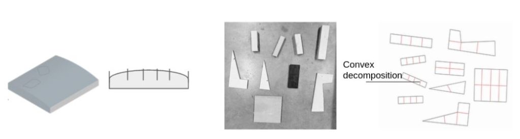
Design System – Surface Tiling
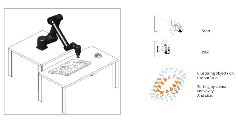
Nesting objects on the design surface:
1 Adjusting contouring to achieve packing on the surface
2 utilizing K-means clustering to map the objects onto the Contours (heat method) of the surface
3 Sorting the pieces by color, convexity and size
Alternative:
Physics simulations to
Nest on the surface. In 2D and 3D
Technology Overview
Technology Overview [Solution]
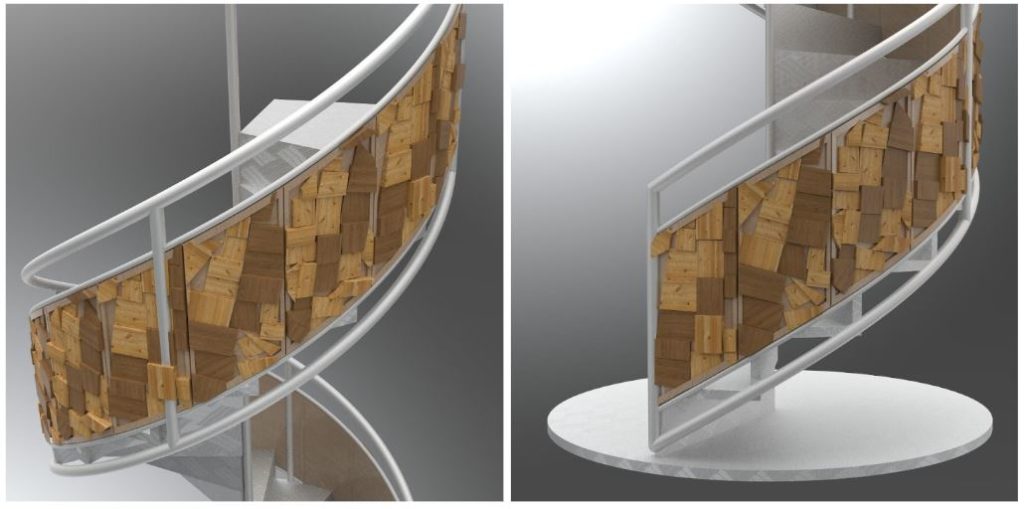
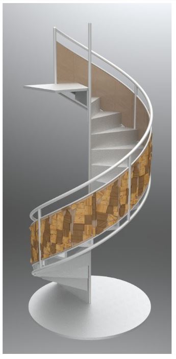
Proposal
A Balustrade from Tiling System:
Proposal – 1 week /4 week of production
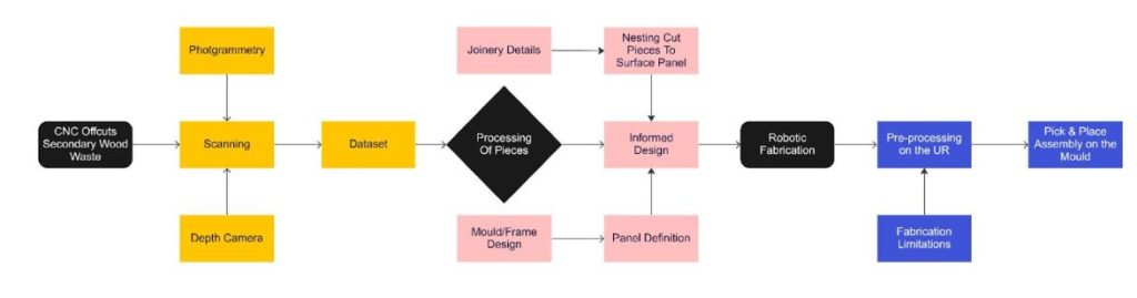
Design Input
Nesting Cut Pieces on Surface Panel:
- Define the Mold / Frame
- Resin on the Mould
- Nesting Cut fragments on Surface panel
Production Estimate – Prototype II
Processing Time per panel
Scanning
- Pick & Place (Bin picking and Sorting) – 40 operations. 30 minutes per panel
- Scanning on the UR – 10 minutes
Robotic Fabrication
- Algorithm Solution Time – 2 minute
- Cutting on the Circular Saw – 1 typical cut = 2m = 4 min
20 cuts – 30 minutes.
- Pick & Place (Assembly)- 40 operations. 30 minutes per panel
Per panel – 2 Hours
Material and opportunity Cost
Secondary Wood Waste – Free
Moud – To be manufactured once, reusable
Resin Binders – Bio resins can make it sustainable
Robot Runtime – Assembly might be manual and AI assisted
