Working in 3D CAD environments can be restrictive. While most CAD software provides tools for creating shapes and generating ideas, they often rely on a mouse and keyboard, or are very expensive. “Shape it, Feel it” investigates opportunities to generate shapes using a computer’s webcam and hand gestures. We utilize cheap and readily available hardware components to add haptic feedback, aiming to create a gamified, affordable, and interactive way to interact with digital geometry.
To showcase this, we focused on creating a virtual pottery wheel.
Process
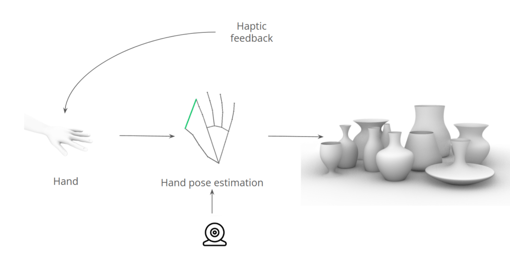
Our overarching goal was to create shapes with our hands using the webcam, while also providing haptic feedback. We started by outlining the basic workflow, envisioning an intuitive and interactive experience. To achieve this, we experimented with various approaches, which we will detail here.
Python/OpenCV
Our first attempt involved using Python, OpenCV, and MediaPipe. The aim was to create a curve on the screen that users could interact with by touching each control point, allowing them to deform the curve. While this approach worked well for visualizing and manipulating the curve, it lacked haptic feedback and was limited to a two-dimensional interface.
In our next attempt, we coupled a version of the code with a game engine to revolve the points into a 3D object. This approach successfully created and visualized 3D geometry, but it still didn’t meet the interactive nature we desired for this project. We decided not to pursue further debugging of the 3D viewer and instead moved on to exploring a different tool altogether.
Unity
While none of us had prior experience with Unity, we decided to attempt creating the pottery wheel in this platform due to its many advantages: robust 3D engine, cross-platform support, and extensive asset store. To achieve our goal, we tackled the problem from two sides: hand tracking and shape manipulation. For hand tracking, we used a Python Mediapipe CV script to track our hand joints and send that information into Unity. This approach worked really well, and we successfully imported all the necessary data into Unity.
Grasshopper
Our last and final approach, due to the short nature of this project, was to use Grasshopper. Our group is quite comfortable with Grasshopper, but using Vision to live manipulate is something that is new. This has also only been possible due to the release of Rhino 8 running Python 3 and supporting libraries such as OpenCV and MediaPipe. This saved us from bridging into Grasshopper from Python and meant we could do it all locally. We created many iterations of the code that would manipulate the surface. In Grasshopper we utlized many different plugins and logic solutions to reach the end goal of creating a pottery wheel. The general concept was always just a line which we can manipulate with spheres which are placed at the end of the thumb and pinky.

After experimenting with many different versions, we finally achieved the desired functionality. We can now manipulate the shape of the vase with our right hand and save the design with our left hand. This development brought us significantly closer to a fully functioning version.
Hardware
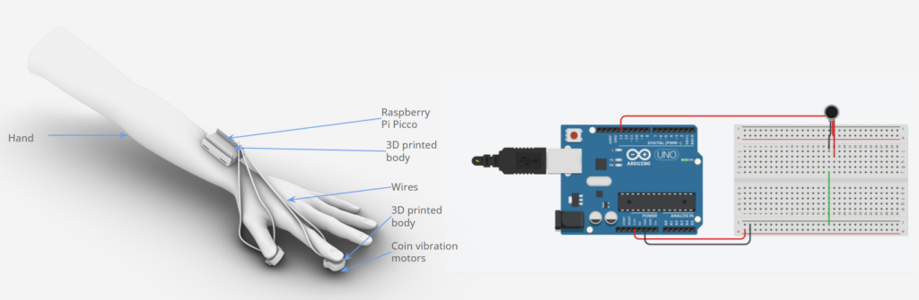
To achieve our goal of providing tactile feedback when interacting with the vase digitally, we needed to develop a hardware component. We created a low-cost, DIY tactile sensor for the fingers. Coin vibration motors at the fingertips vibrate in response to the user’s interaction with the design. By knowing the position of the hand and its interaction with the Grasshopper component, we can control the vibration intensity.
In Grasshopper, we created a script that tracks each finger’s distance to the cylinder’s centerline and clusters it into values between 0 and 50. Higher values correspond to less vibration. These values are then sent via OSC to Python through a USB bridge to the Arduino. While a more elegant wireless solution would have been preferable, we opted for a wired setup due to time constraints and the correct boards not arriving in time.
The Final
The final design proved to be effective for the goal we set out to reach. We incorporated a shelf to store previous designs, which are automatically exported as separate Rhino files. Looking ahead, we aim to enhance this system further. Firstly, we plan to reduce glitches by implementing better vision components. Additionally, we want to make shape editing more progressive rather than the current extreme changes. Another potential improvement is to enable direct sending of saved files to a 3D printer, allowing immediate physical prototypes from digital experiments. This project represents an intriguing exploration of the interaction between digital and physical elements in the creative workflow, with many more possibilities to explore.