
Advanced toolpath design for FDM process
Students will design and simulate a toolpath for a small object intended for interior or product design. The focus is on exploring creative toolpath strategies, especially non-planar slicing, where the toolpath height changes across the object. Students must design a non-planar path and use attractors to locally deform the lines in a meaningful, design-driven way.
The toolpath should consider printing constraints such as layer height variations, line thickness, speed limits, maximum angles, and overlapping between lines. The final result should show how toolpath design influences both the function and the aesthetic of the printed object.
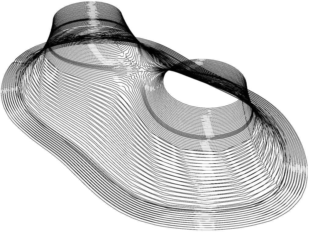
Strategy | Base mesh


Strategy | Toolpath


(Distance between lines 0.5mm)

(Distance between lines 0.25mm7)


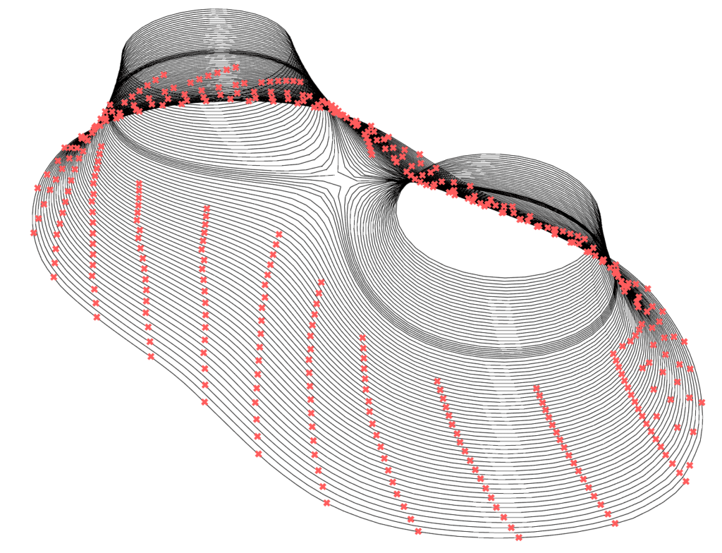


Deform the curves and bring them closer together with kangaroo. Unfortunately, it can not handle the kangaroo curve as a toolpath.

Result | Analise for printing


