The Digital Fabrication Collection showcases four prototypes developed through distinct making techniques. Each project explores how form, material, and geometry respond to CNC milling, laser cutting, 3D printing, and robotic fabrication, highlighting the diverse possibilities of digitally driven design.
Light Lattice
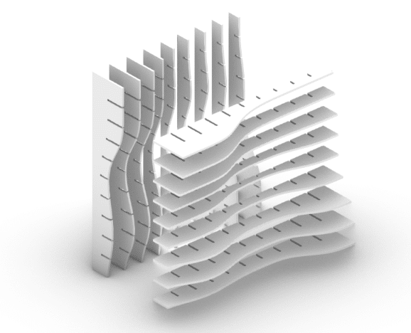
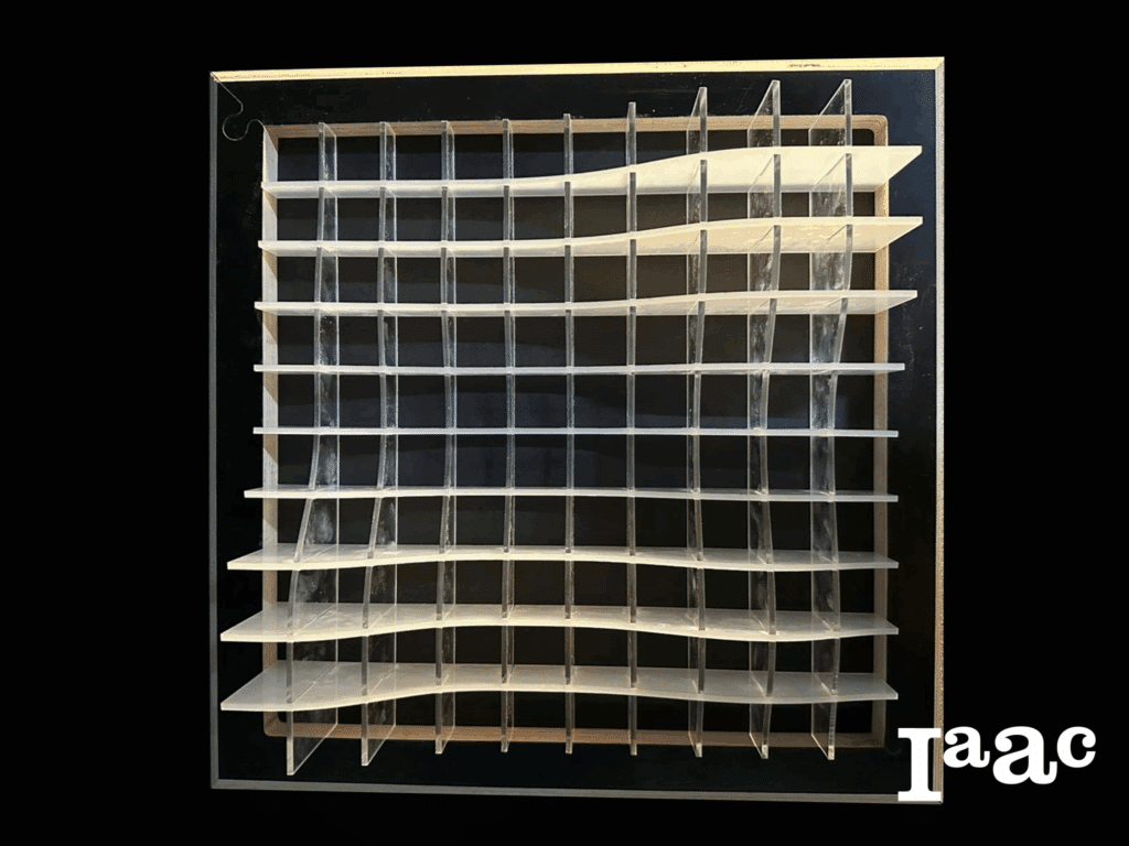
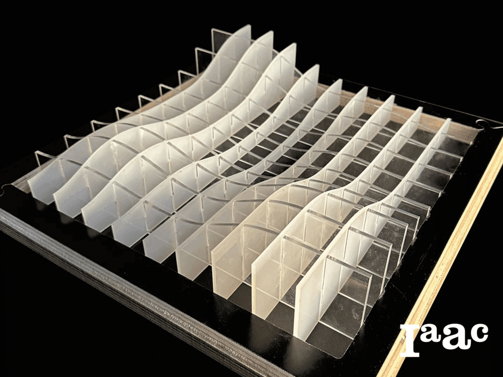
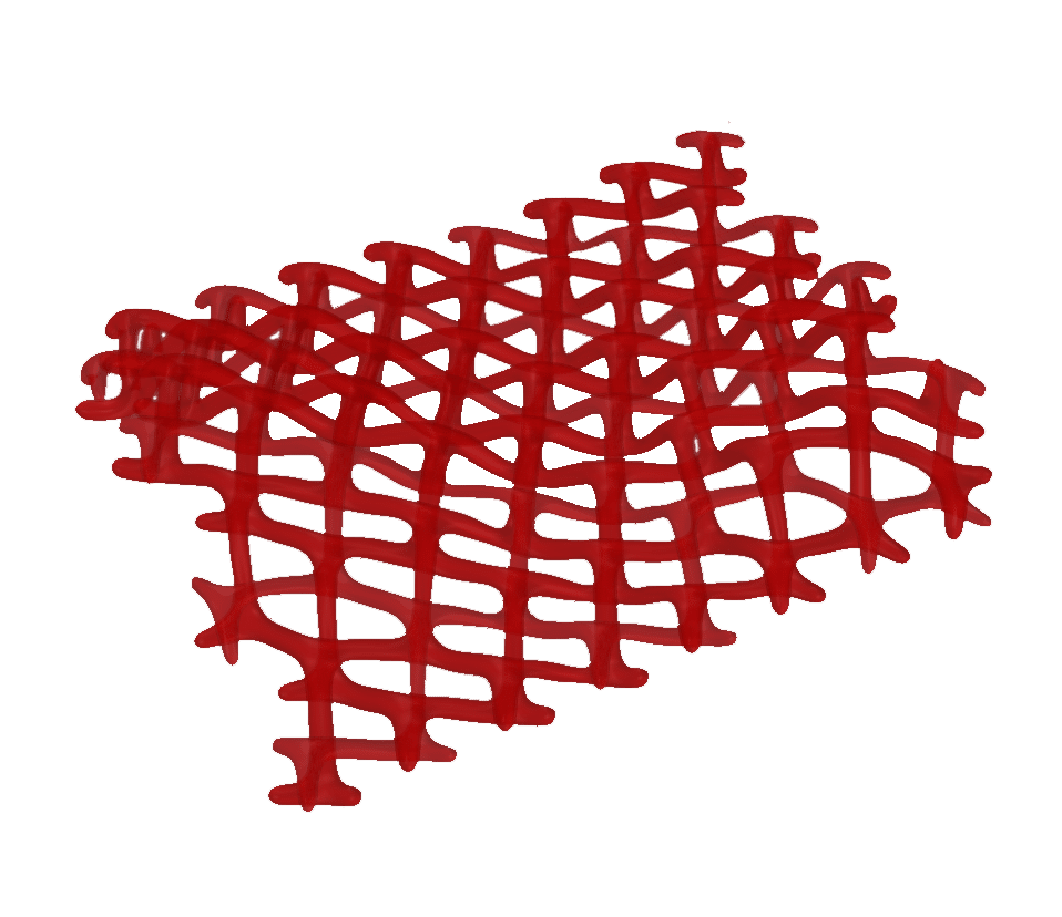
The Light Lattice project explores how laser cutting can translate digital geometry into tangible physical prototypes. By testing how two-dimensional linear patterns can fold, interlock, and form spatial structures that cast expressive light and shadow, the project focuses on using cutting strategies and material properties to generate forms that feel both lightweight and tensioned. Using acrylic sheets as the primary material and employing a sequence of precise cutting, sanding, and assembly processes, the work demonstrates how digital tools support the creation of complex structures and refined visual effects.
Concept and References
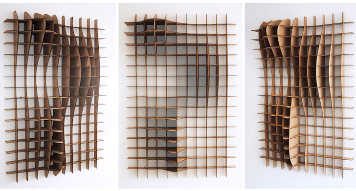
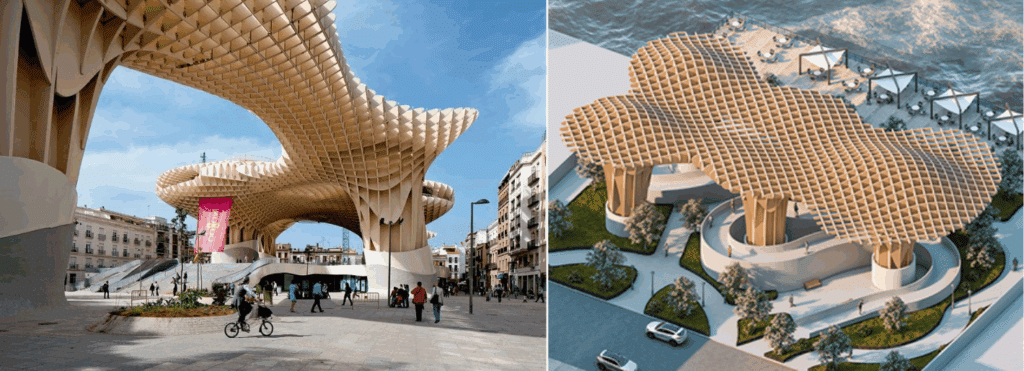
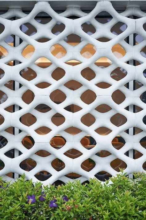
Light Lattice is a grid structure made of interlocking slotted plates. It is lightweight, strong, and material-efficient, often used in temporary exhibitions and experimental architecture. Its layered form creates rich light and shadow effects, giving the space a unique visual rhythm.
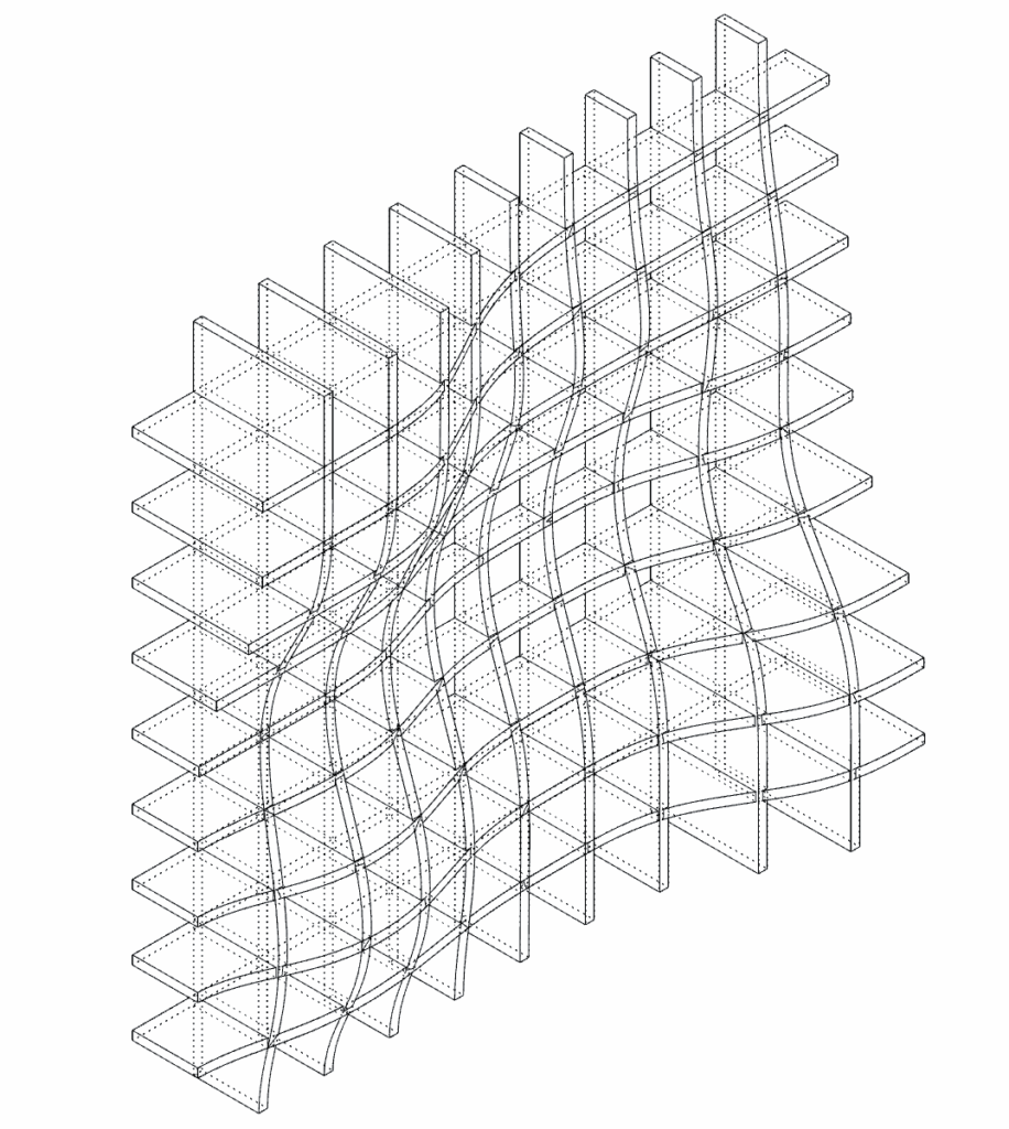
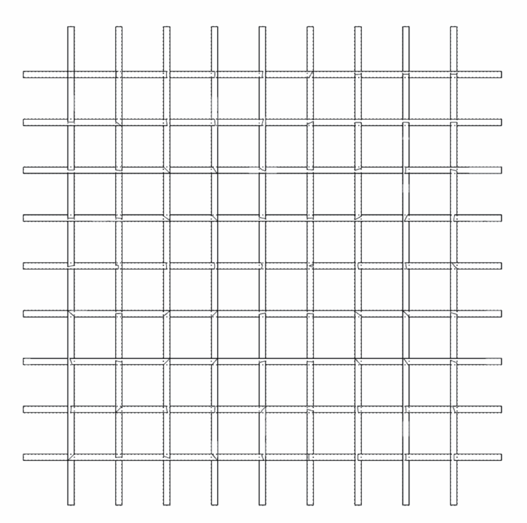
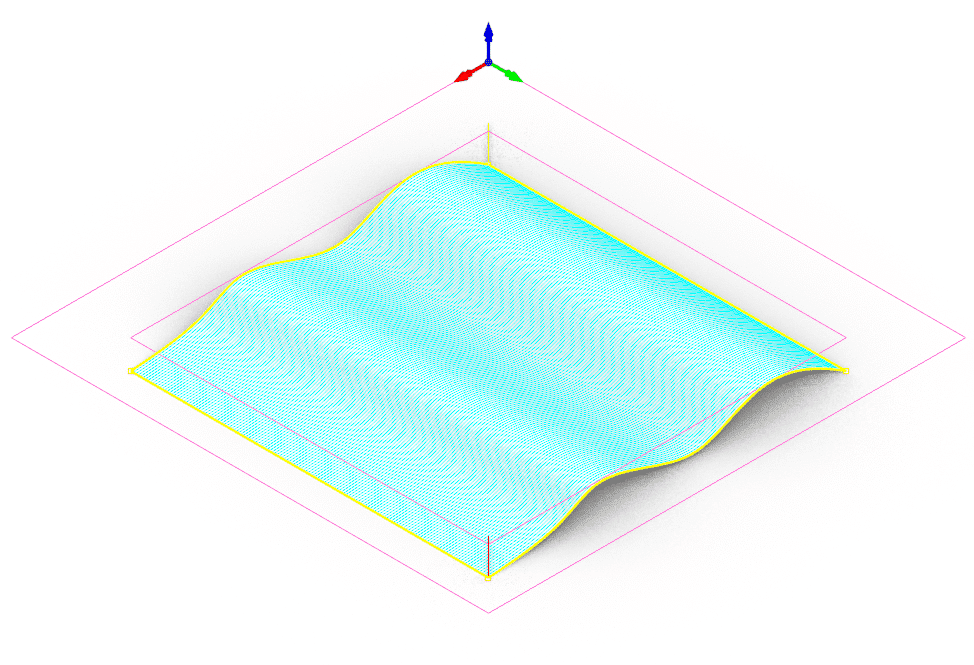
Technical Drawing
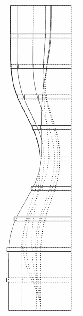
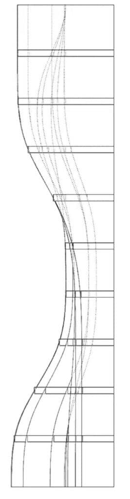
Fabrication Strategy
01 – Setting
Setting curves for the surface and number of horizontal and vertical lines
02 – Shape Construction
Extrude and shape the design
03 – Slicing
Slicing and setting joint and tolerance
04 – Cutting
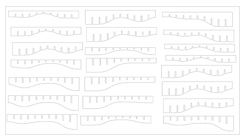
Use machine to cutting the pieces
Material: 3mm Acrylic sheet
Power: 90
Speed: 1.2
05 – Assemble
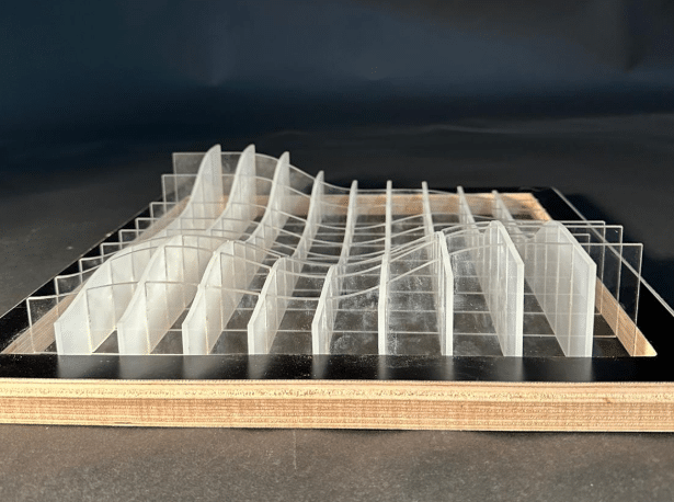
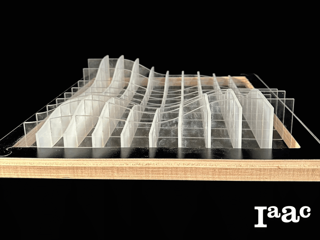
Assemble all the pieces and place them into the frame
Final Design
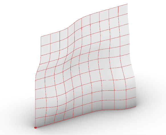
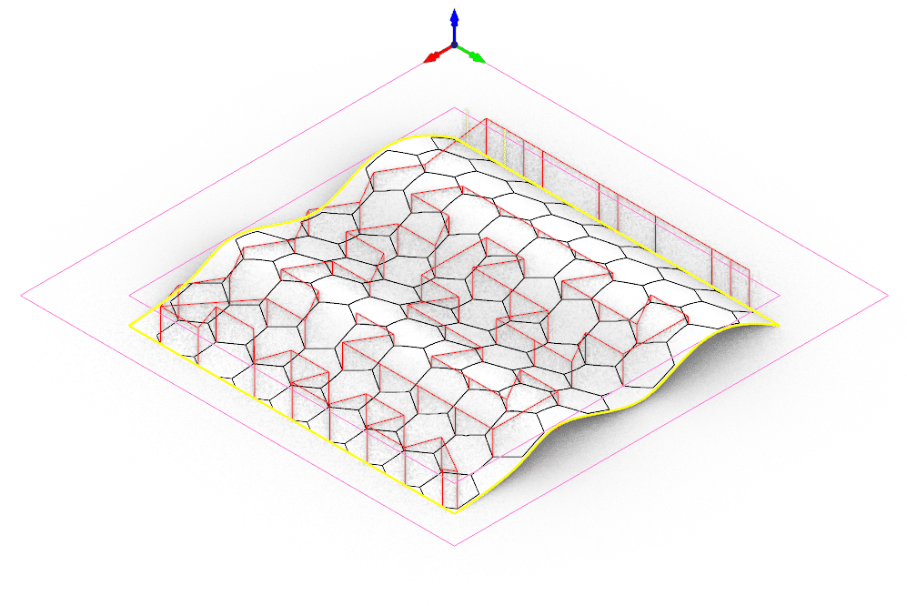
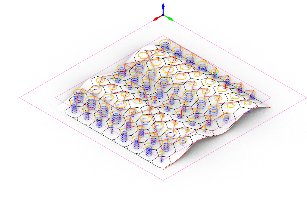
HexaFab
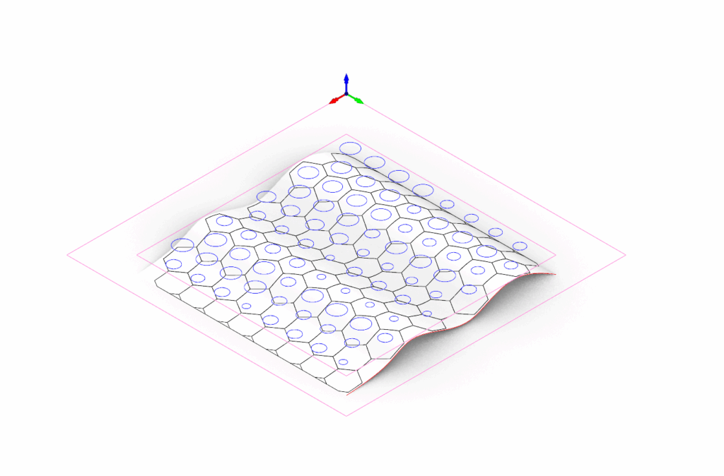
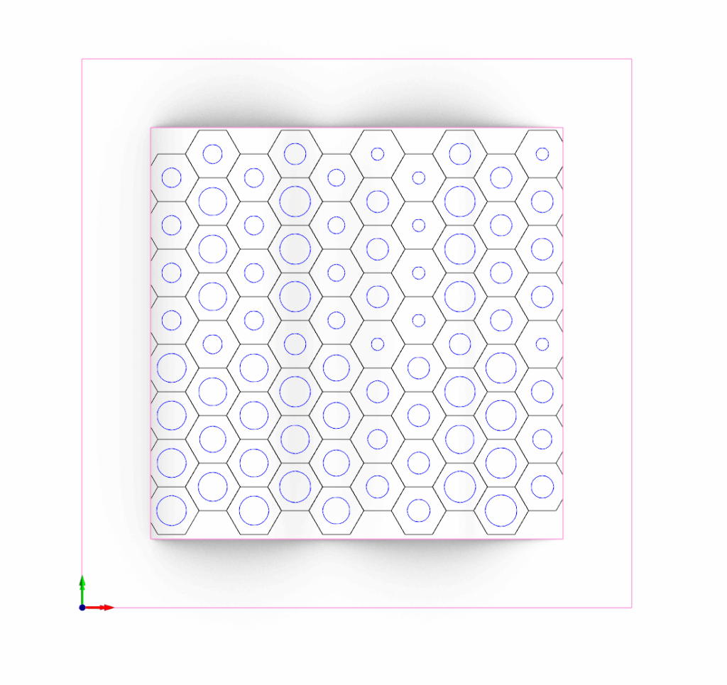
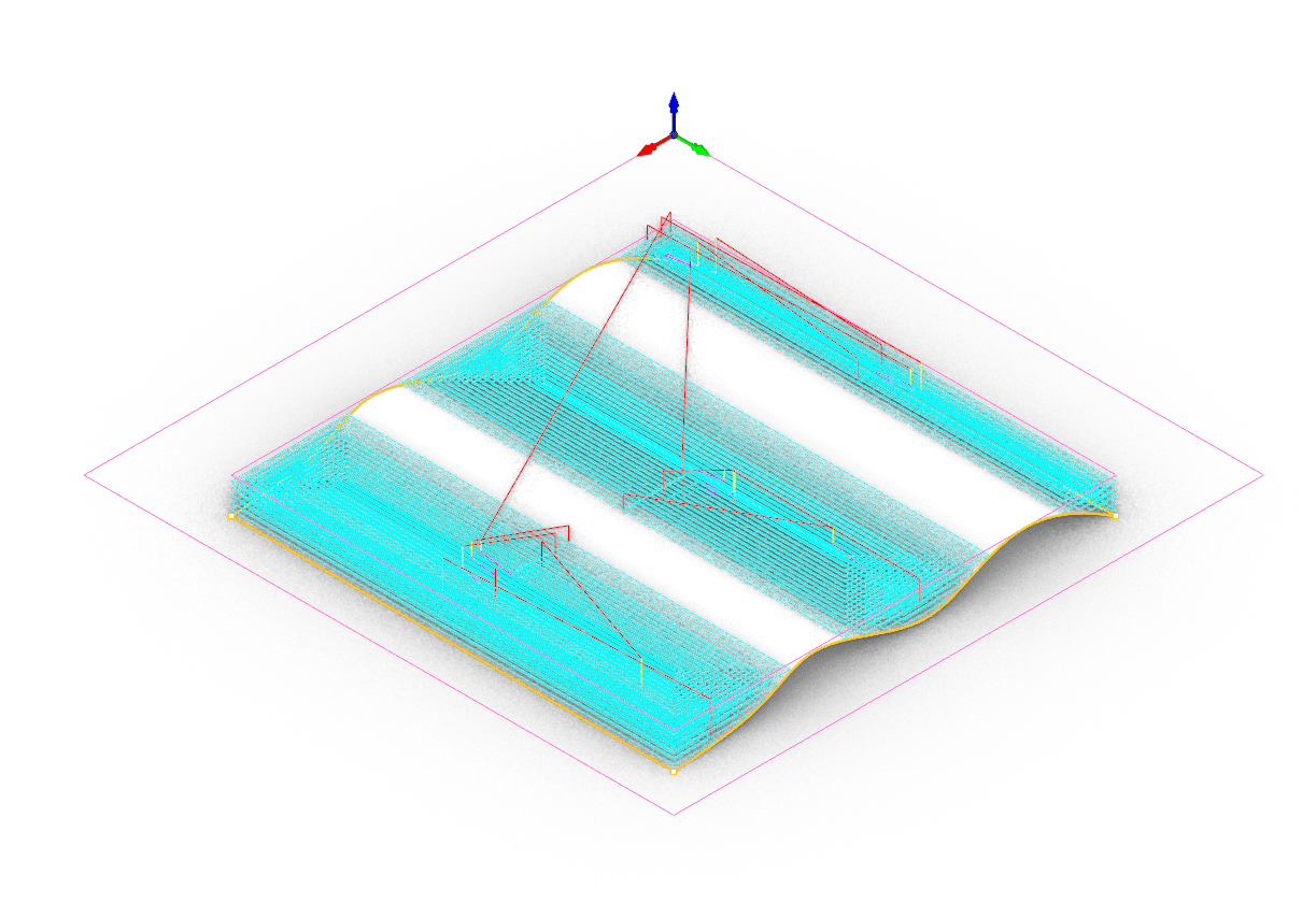
HexaFab project explores the use of CNC fabrication to translate digital geometry into a tangible prototype. By testing how curved surfaces interact with projected patterns, it focuses on generating fluid forms through precise machining. Using cork and a sequence of controlled milling operations, the work highlights how digital tools support the creation of refined design pieces.
Concept and References
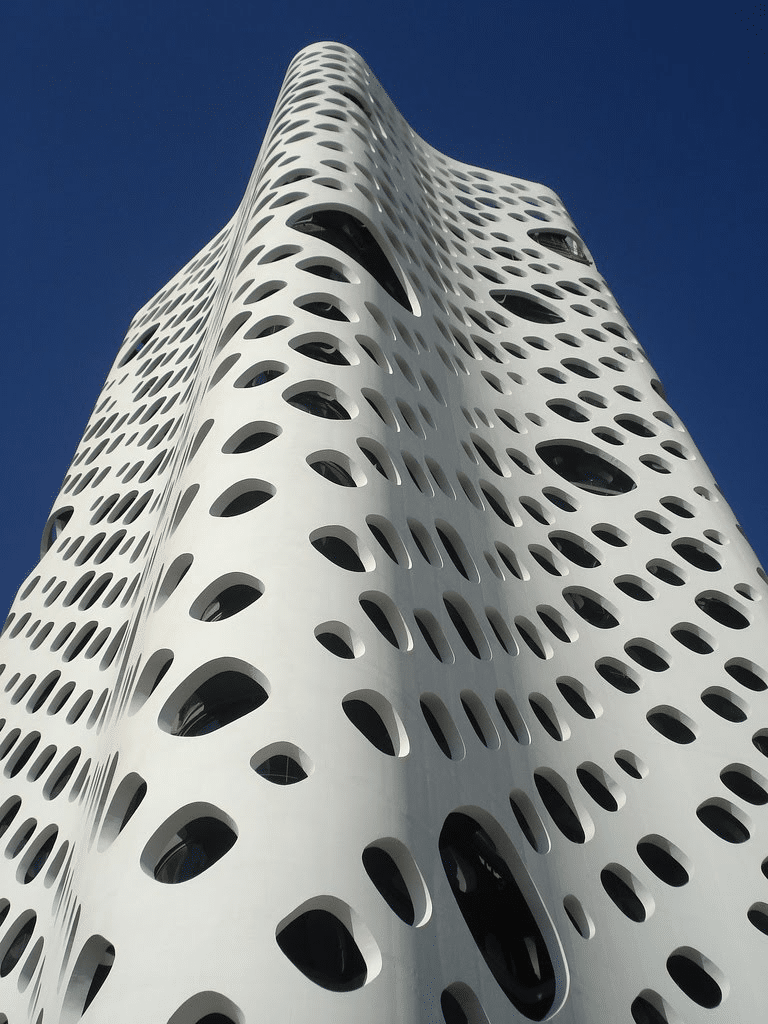
The design focuses on combining two geometries (hexagon and circle) in a curved surface.
With the projection of these geometries, it is possible to get a flowy design with the feeling of movement.
CNC machine enables this process by combining fabrication techniques.
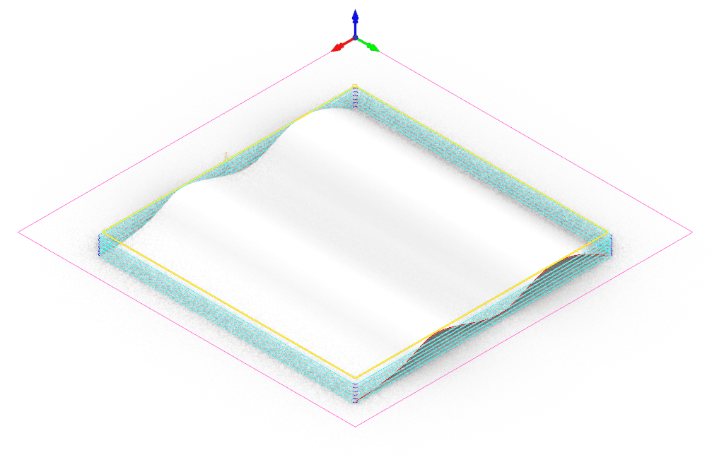
Technical Drawing
Fabrication Strategy
01 – Workpiece

Material: Cork
Machine: Raptor
Post Processor: CNC_STEP_BCN Raptor
Workpiece volume: 300x300x30mm
02 – Secure Workpiece
The workpiece was secured to the CNC bed with nails and a wooden board to ensure stability during machining.
03 – Horizontal Roughing
Ball Mill
Flute: 2
Diameter: 8mm
Spindle Speed: 12000
Cut Direction: Upcut
Stepdown Control (dZ): 70%
Stepover Distance: 50%
Total mill time: 20.32 minutes
04 – Parallel Finishing
Ball Mill
Flute: 2
Diameter: 8mm
Spindle Speed: 12000
Cut Direction: Mixed
Stepover Control (dZ): 25%
Total mill time: 22.84 minutes
05 – Engraving
Ball Mill
Flute: 2
Diameter: 8mm
Spindle Speed: 12000
Cut Direction: Natural
Location of cut geometry: at top
Total cut depth: 16mm
Total mill time: 11.32 minutes
06 – Profiling
Flat Mill
Flute: 2
Diameter: 6mm
Spindle Speed: 12000
Cut Direction: Mixed
Location of cut geometry: at top
Total cut depth: 30.5mm
Cutting side: Right of curves/Inside
Total mill time: 12.89 minutes
07 – Profiling (Offset Frame)
Flat Mill
Flute: 2
Diameter: 6mm
Spindle Speed: 12000
Cut Direction: Mixed
Total cut depth: 20mm
Cutting side: Right of curves/Outside
Total mill time: 2.46 minutes
08 – Profiling (Detach Model)
Flat Mill
Flute: 2
Diameter: 6mm
Spindle Speed: 12000
Cut Direction: Mixed
Total cut depth: 30.5mm
Cutting side: Right of curves/Outside
Total mill time: 4.10 minutes
09 – Fabrication
Final Results
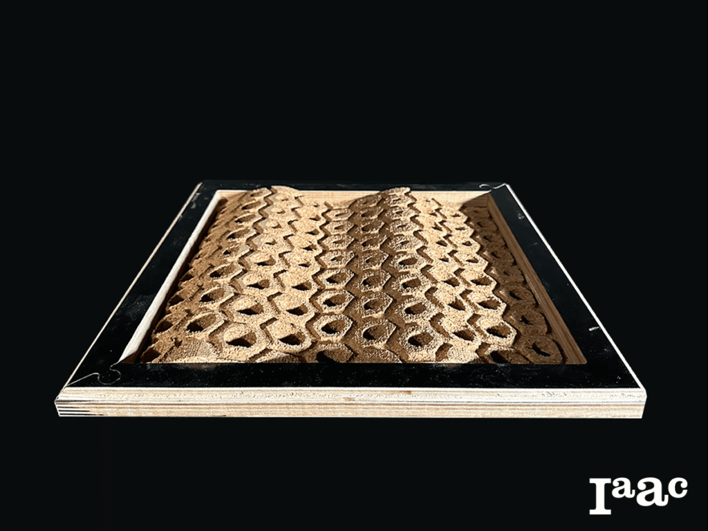
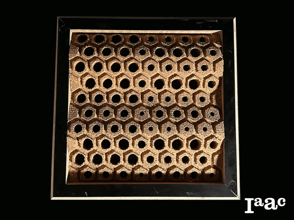
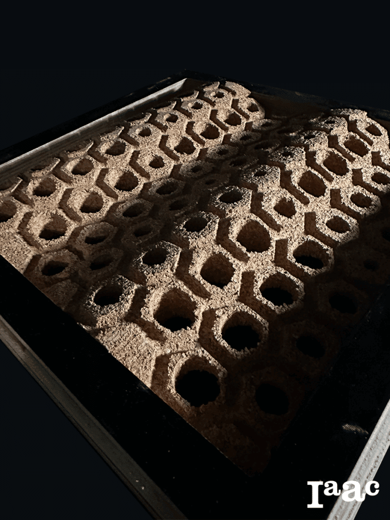
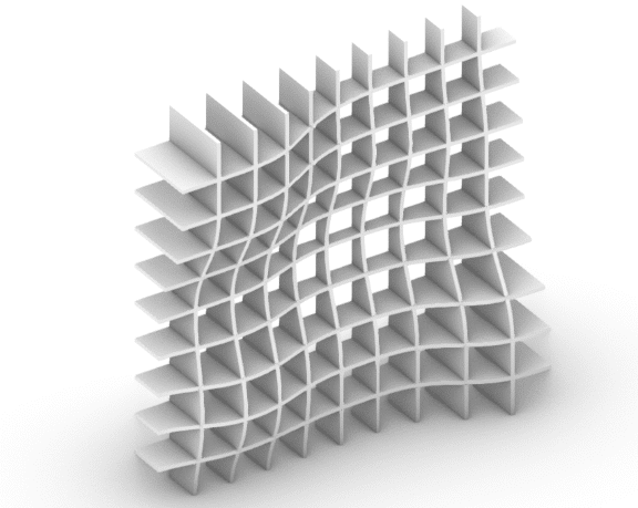
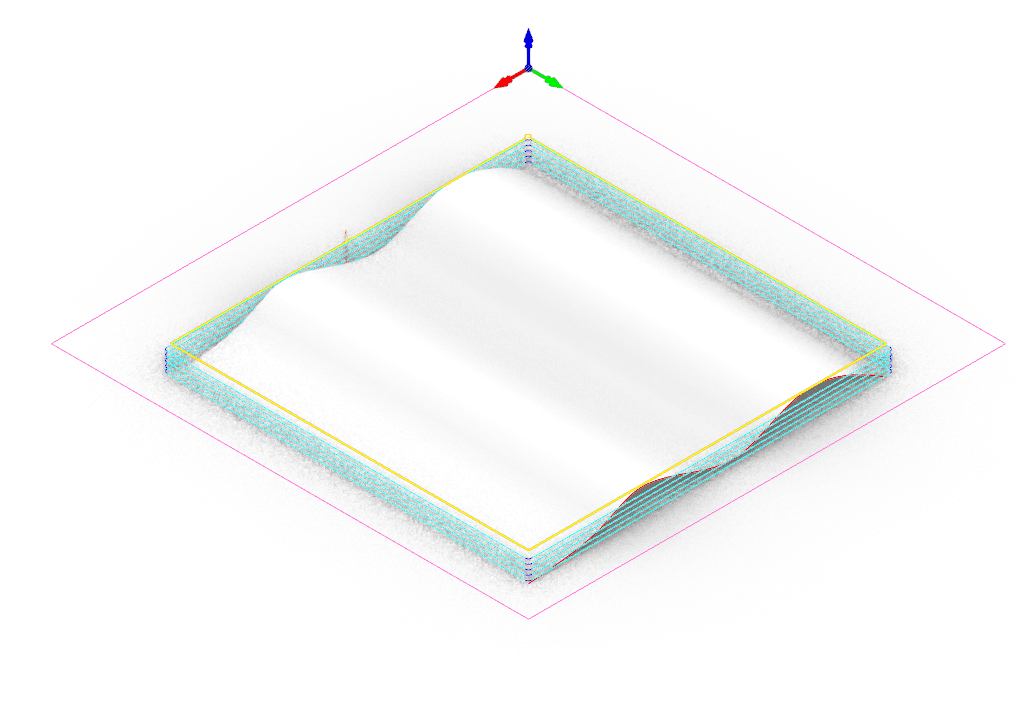
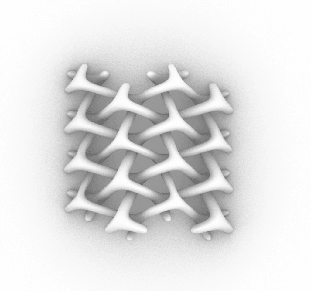
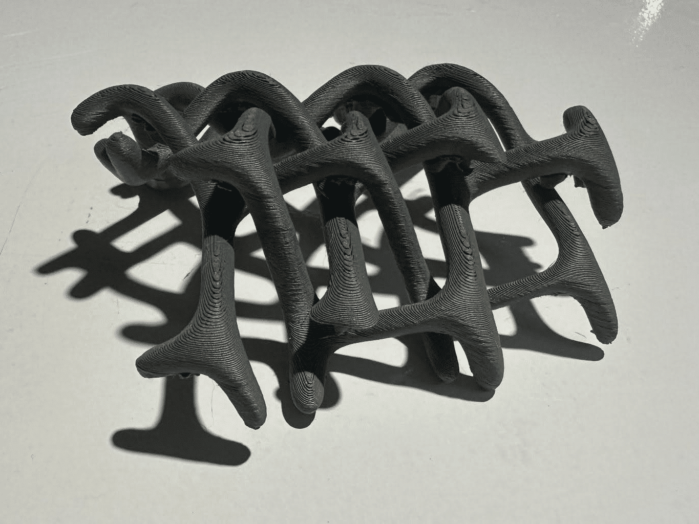
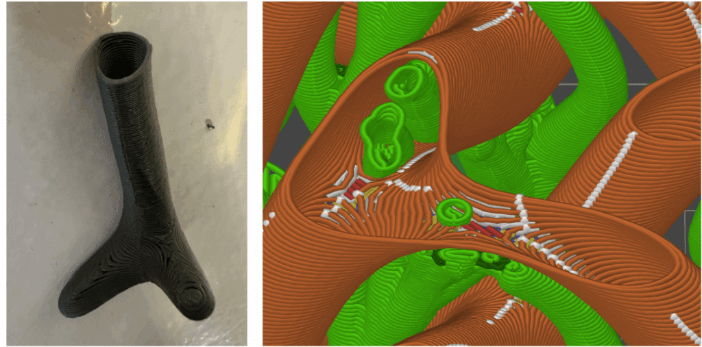
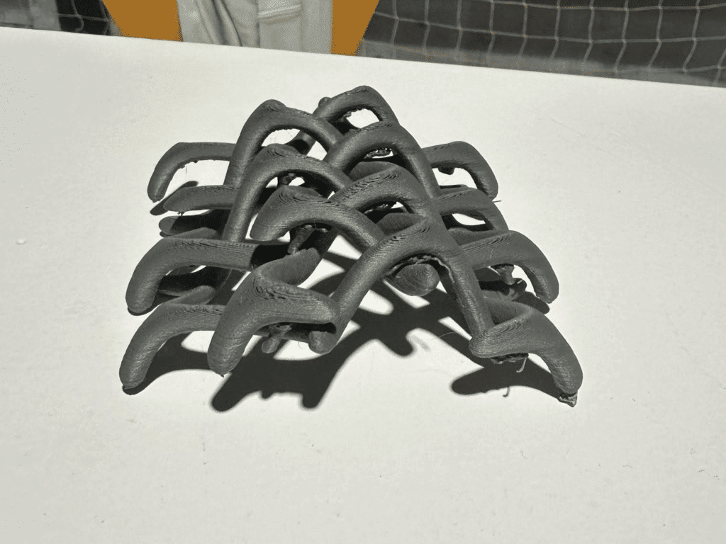
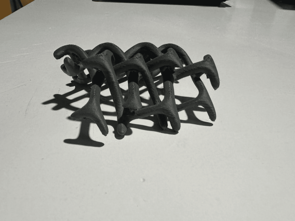
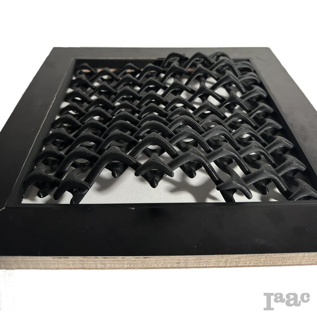
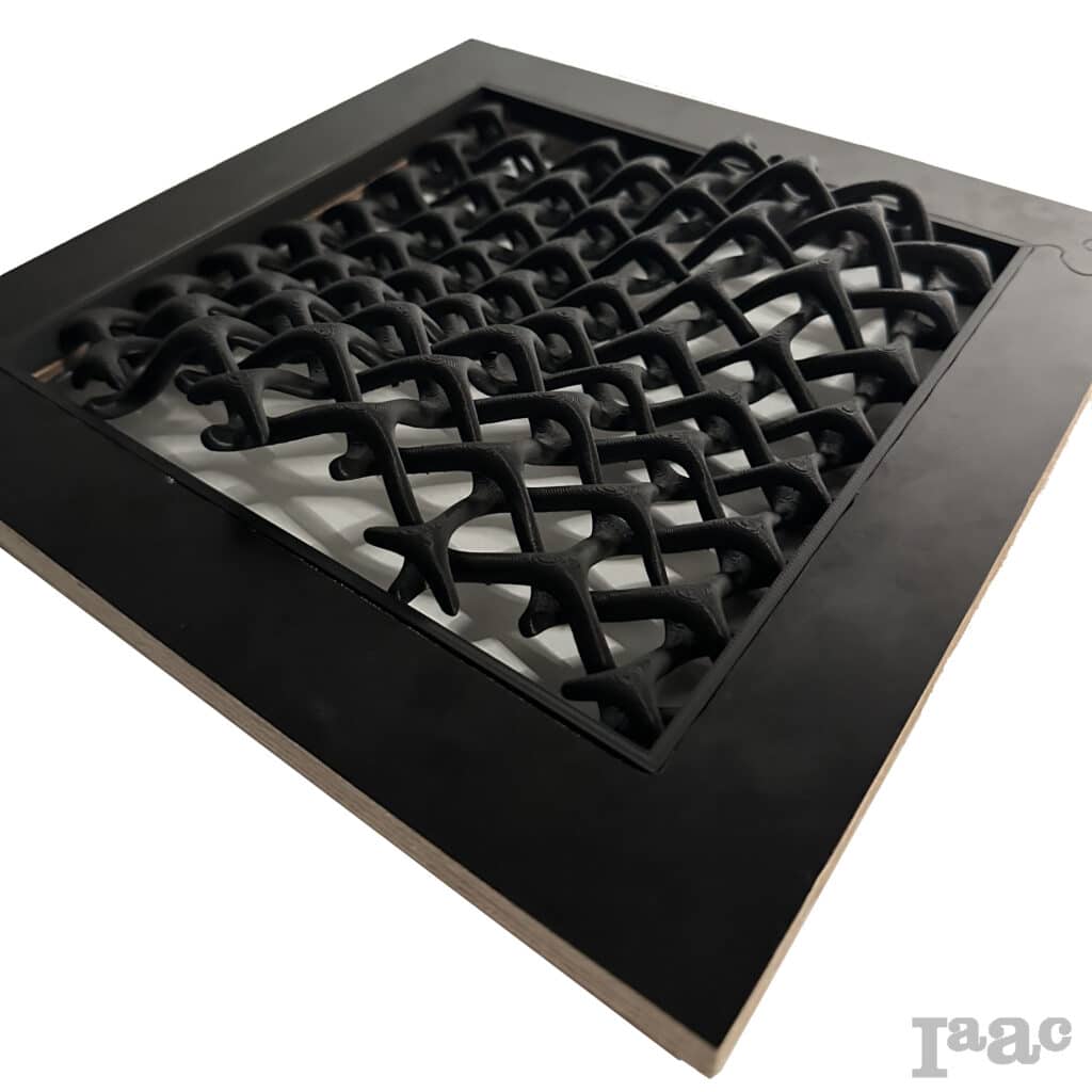
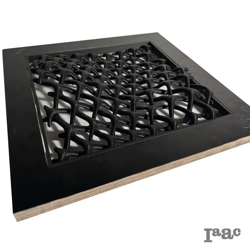
Interwoven Skin
This project investigates how digital fabrication can generate complex spatial structures through 3D printing. The study focuses on converting a digitally modeled pattern into a physical piece by testing form, geometry, and material behavior during printing. The prototype serves as an exercise in understanding how additive manufacturing manages curvature, structural continuity, and support requirements within a compact architectural model.
Concept and References
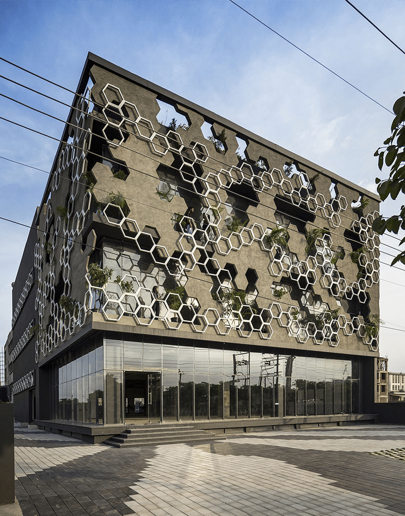
Interwoven Skin is inspired by the woven texture aesthetics of architectural facades.
It transforms the rhythmic pattern and perforated facade system into a three-dimensional form through additive manufacturing.
Its form centers on an interlocking woven structure.
Process and Design
Test Protorype
1 – Modeling
2 – Import to Bambu Lab
3 – 3D Printing
Final Design
1 – Modeling
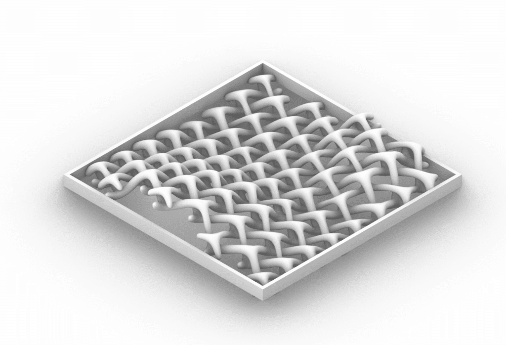
2 – Framing
3 – Import to Bambu Lab
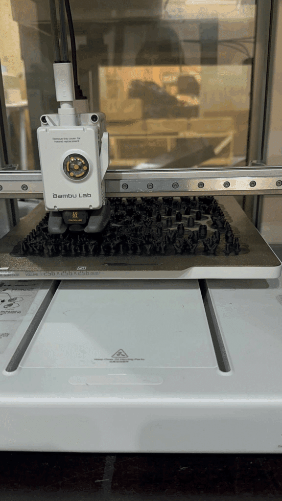
4 – 3D Printing
Design Process
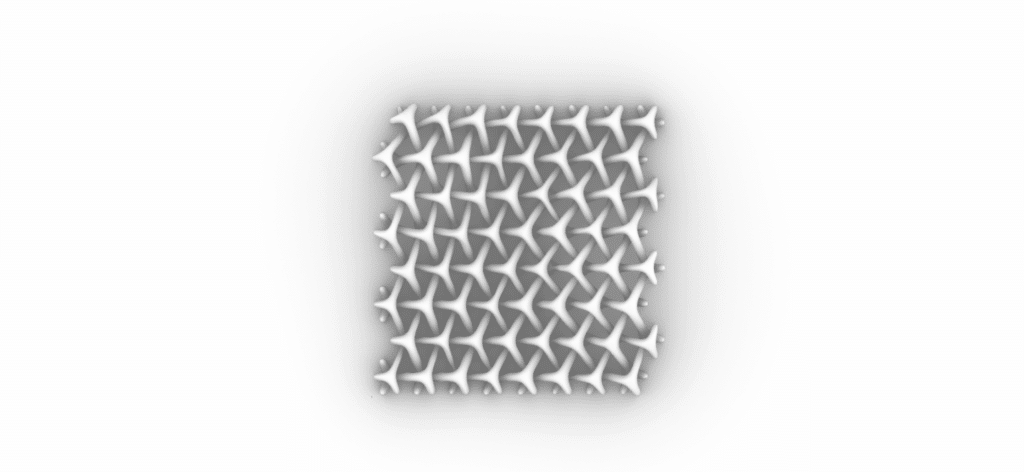
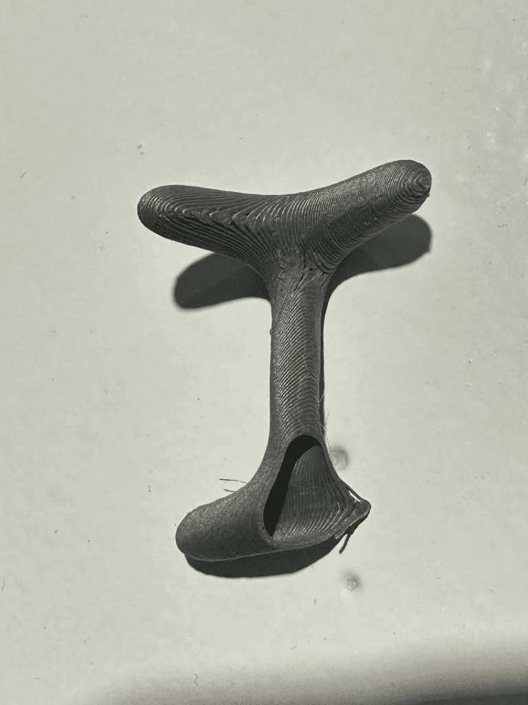
1 – Hexagonal Grid
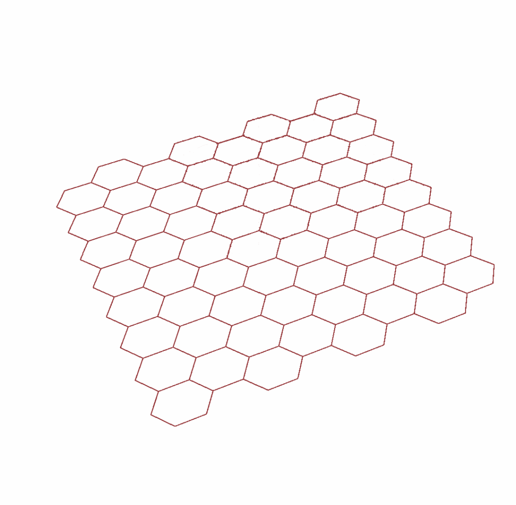
Hexagonal grid with parameterized columns and lines.
2 – Apply grid on surface
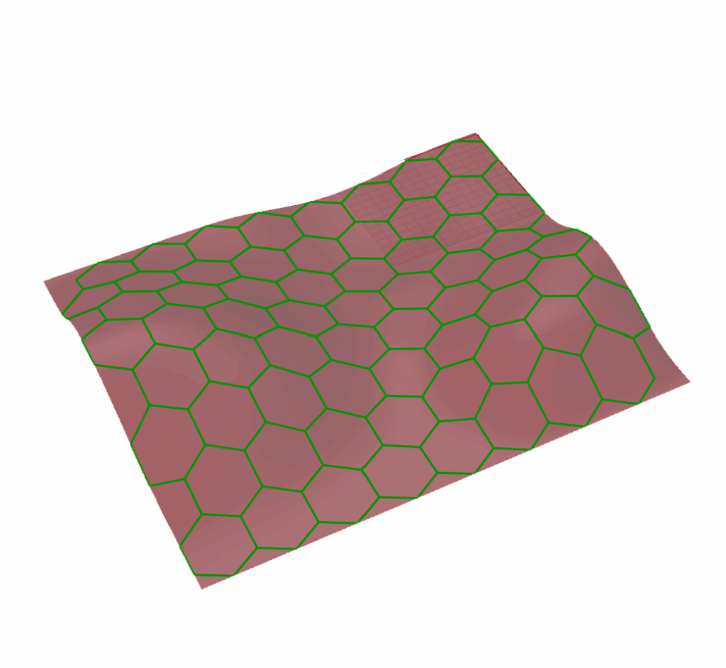
Surface manipulation into a curved one and application of the hexagonal grid.
3 – Mesh’ Skeleton
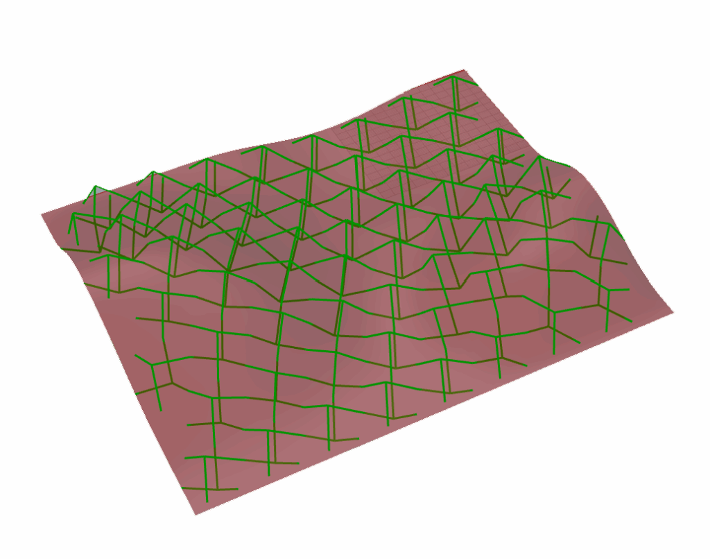
Connect average point (moved in -z e +z) of the hexagon with the middle point of each edge.
4 – Meshes created
Through the lines, create meshes and apply thickness.
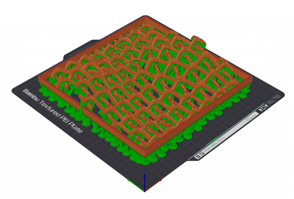
Fabrication Strategy

Parameters
Material: EPLA
Machine: Bambu Lab A1
Workpiece volume: 200x200x30mm
Total Filament: 186.84 g
Model Filament: 126.49 g
Support Time: 3h42m
Top Z Distance: 0.25
Model Printing Time: 13h17m
Total Time: 13h30m
Optimization
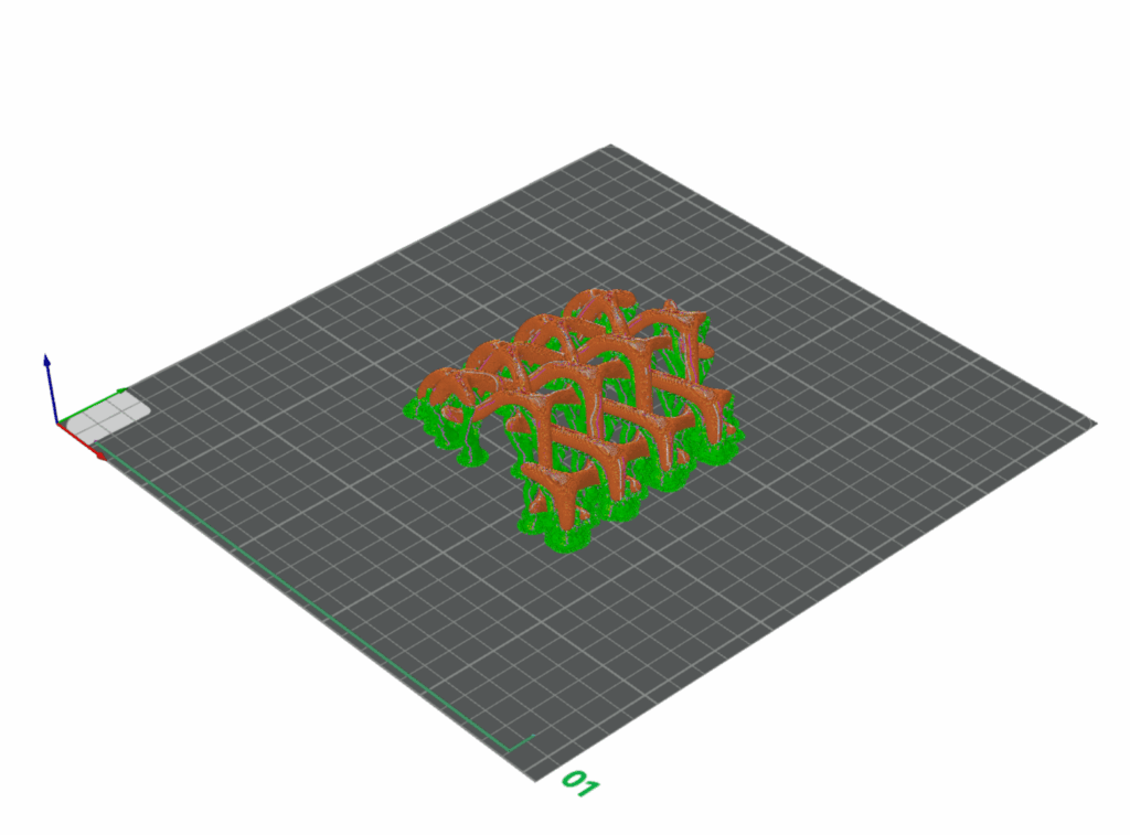
In separating the support and the prototype, some pieces broke due to the thinness of the model. The prototype was a shell.
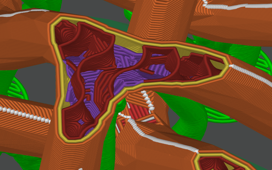
The solution was to transform the model into a solid and to increase the number of wall loops to 2. This way, the model is less fragile and can be separated from the supports without breaking.
Prototype
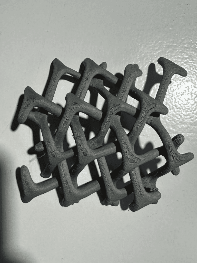
Final Design

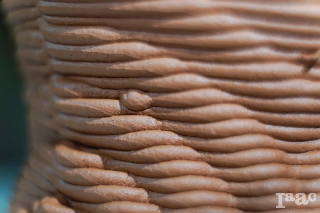
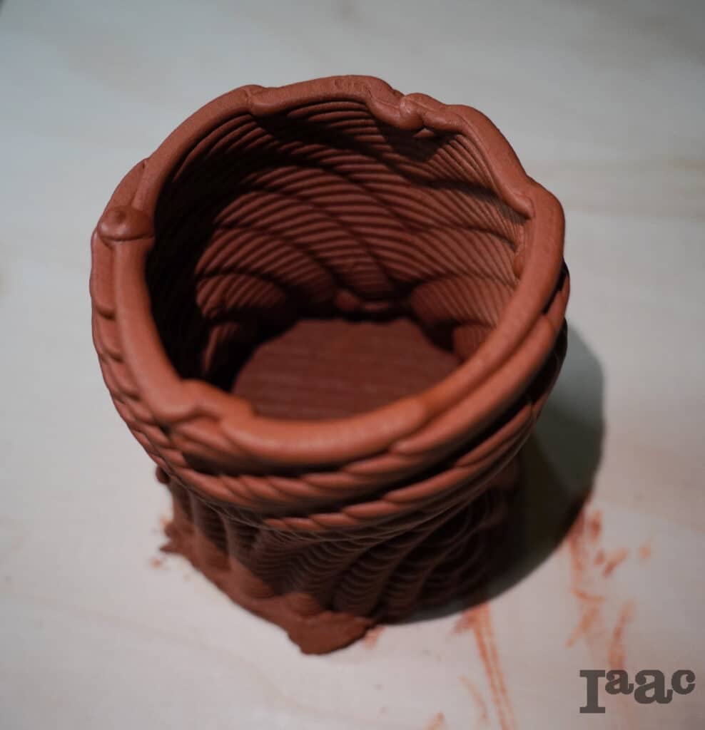
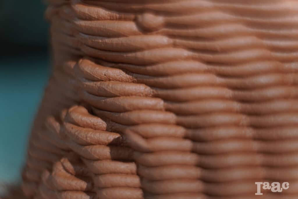
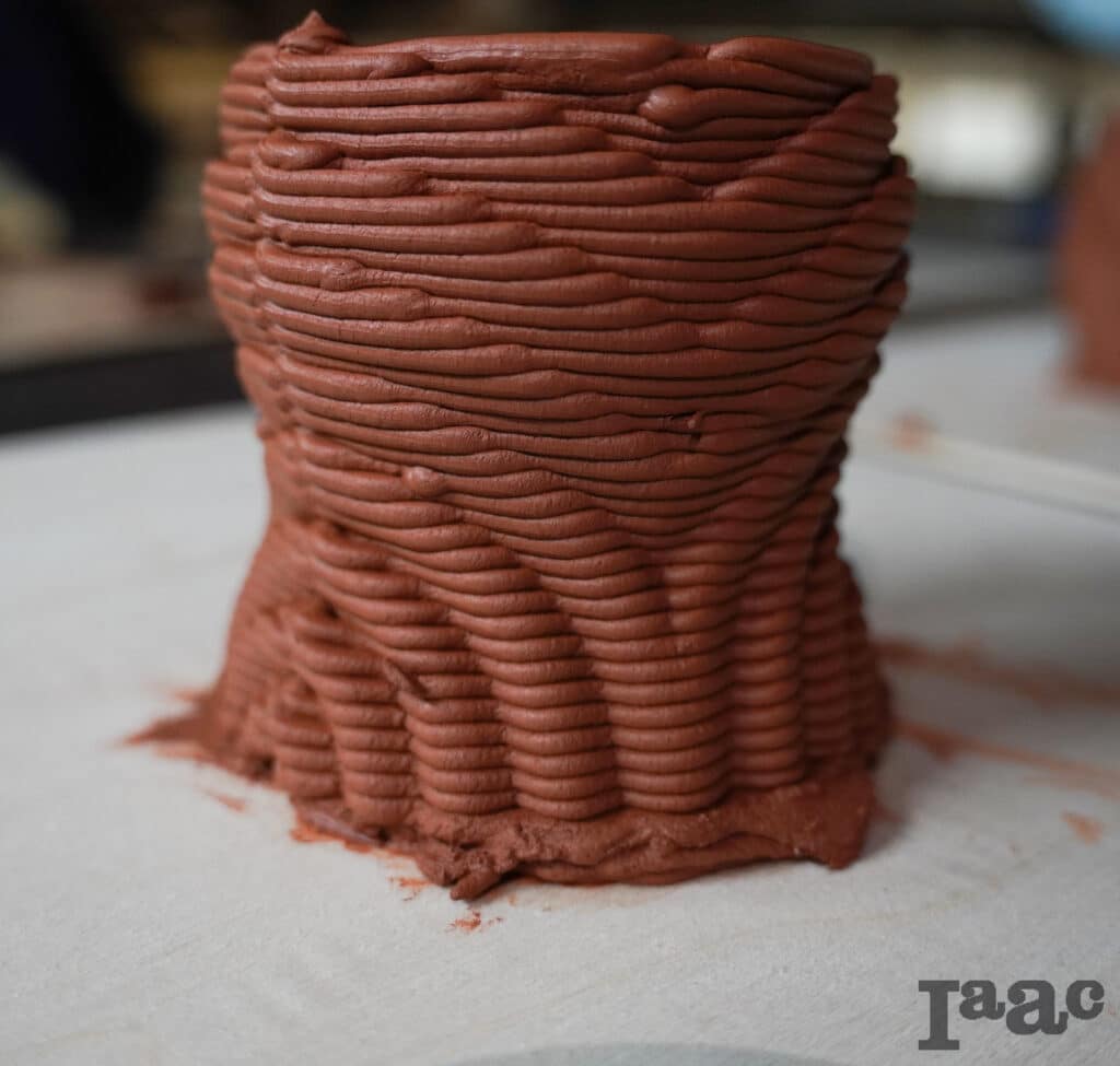
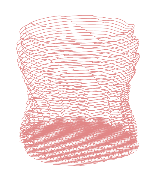
Claywave
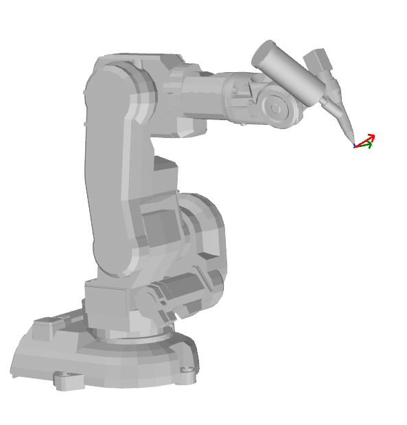
This project is the result of an iterative exploration into clay 3D printing with a six-axis robotic arm. Starting from a digital model, we generated the toolpaths, calibrated the robot, and prepared the clay to ensure a stable and consistent extrusion. Through hands-on testing, the design evolved in response to material behavior and robotic constraints. The final piece reflects this dialogue between digital precision and the natural variability of clay, showing how computational design can adapt to the nuances of physical fabrication.
Design generation
1 – 3D Model

2 – Contour
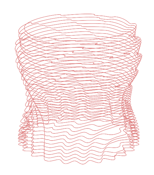
3 – Base Generation
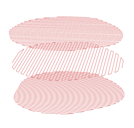
4 – Final Geometry
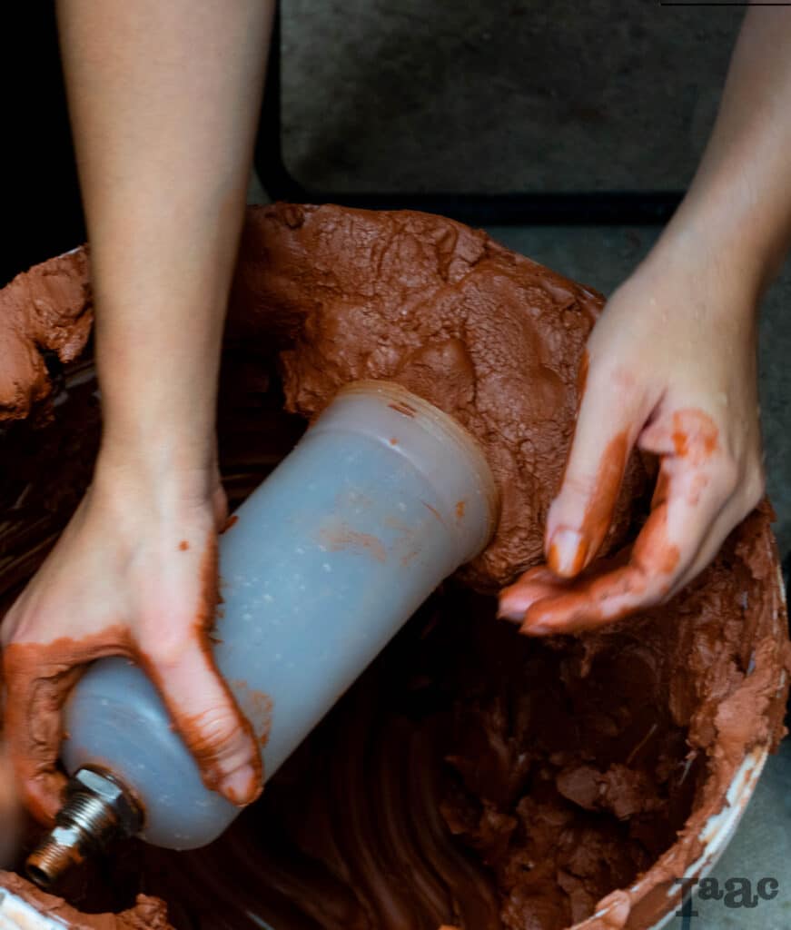
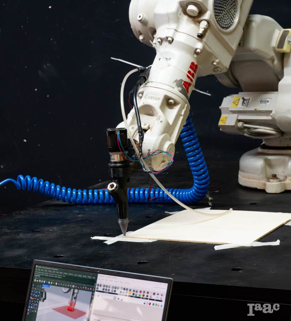
Fabrication
1 – Material Preparation
2 – TCP calibration
3 – Base plane calibration
Fabrication Tests
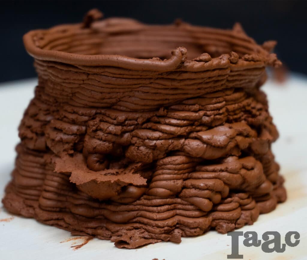
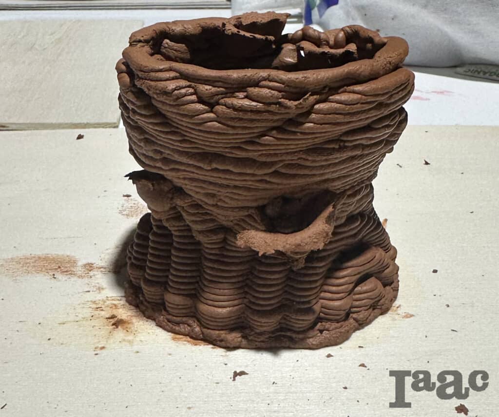
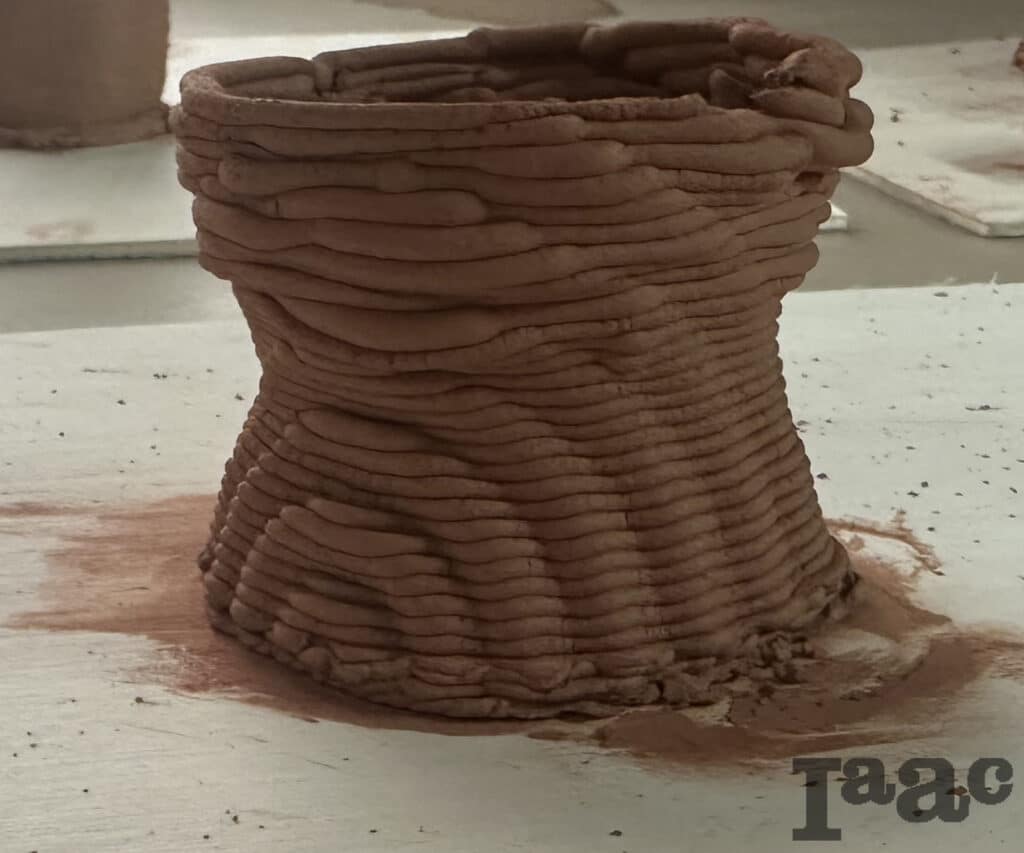
We encountered issues during material preparation. The clay was not properly loaded into the cartridge, which caused air bubbles to form during printing and compromised the final piece. In addition, we realized that the original design was not suitable for this printing method: the vessel narrowed too much in the central section and risked collapsing. We reduced the width of that area, achieving a more efficient and stable design.
Final Design