
Designing a small earth 3D printed structure with two or more support points that spans over a person and fits within one crane printing radius.
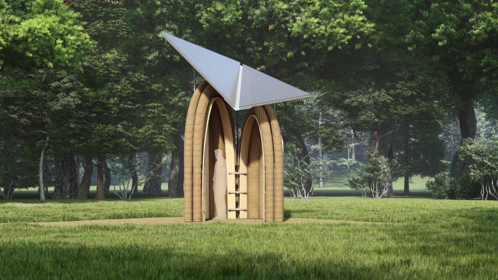
The competition phase’s objective is to create a small, 3D-printed earth structure that can span a person, fits within a crane’s printing radius of 4 meters, and doesn’t require an enclosure. Some vertical surfaces were needed by the design proposal so that it could rest on the ground at two or more points.
Defining the support point/line
For the proposal, a 2 m by 2 m area was selected and multiple iterations were carried out to cover more ground with less material while still maintaining the need for printing vertical surfaces.
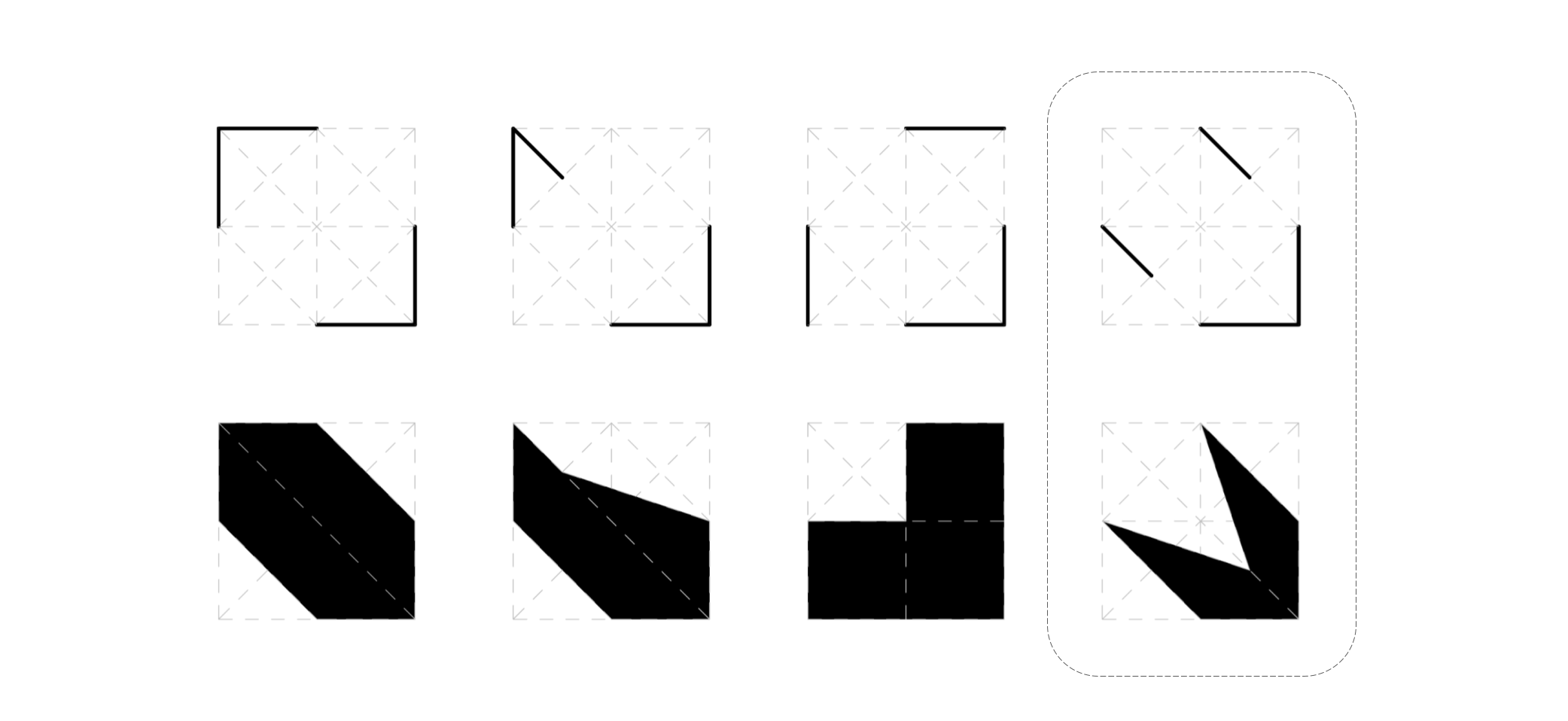
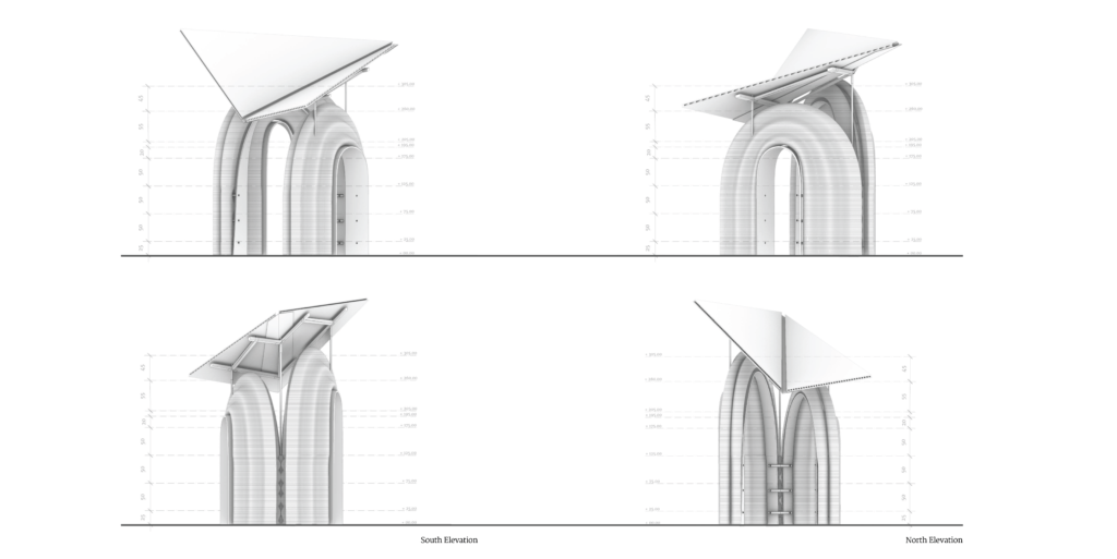
The experience of the proposed spaces was investigated while one person was inside the structure, and the roof coverage area was assessed in light of the wall orientation.
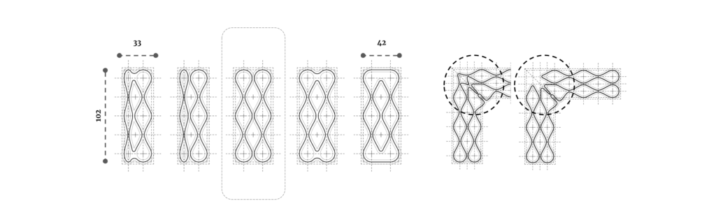
Infill Studies
The next study focused on infill adjustments to achieve minimal material usage while maintaining the structural integrity of the wall. When analyzing the infill, the design’s footprint was considered, modified, and an infill that could accommodate any future structural key inserts was suggested. Cracking that might occur during drying was also considered and was concealed within the folds.
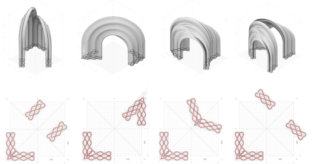
Final chosen geometry and development
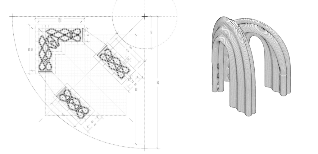
The model above was selected because it was asymmetrical in design due to its variable height after extensive research and consideration of the advantages and disadvantages of the aforementioned geometries. Additional research was conducted on the form finding and placement of the sweep lines from the proposed infills in order to have an opening span for ideal circulation.
Steps for Printing with Embedded Support and Scaffolding system
The next step was to investigate how to build the proposed geometry.
- Step 1 – When the geo polymer foundation is completely dry, the next duty is to attach the timber support on the foundation, which was designed to be supported beneath by a gabion floor. The timber column support will then be fastened to an anchor that is attached to the foundation.
- Step 2 – To this wall, key inset placement was investigated, and the infill opens and closes in order to open, grip the timber key, and shut once more. For the following 120 cm, a straight loft will be produced from the geo-polymer foundation ground up.
- Step 3 – The cantilever support formwork for the Primary & Secondary arched walls would then be fitted with a timber key to hold the wet stage print.
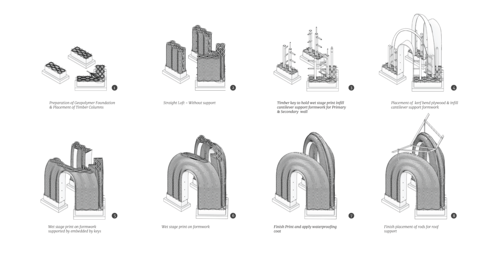
- Step 4 – The key inserts that were incorporated into the straight loft print will now anchor the proposed laminated plywood kerf arch support and infill cantilever support formwork.
- Step 5 – 7 – The next stage is wet stage printing on formwork supported by embedded keys, kerfed arch support, and infill cantilever support formwork after the supports have been embedded.
- Step 8 – The remaining top layers can now be printed, and the attached form work can be taken off. The final step would be to place the last piece of rod for the roof support because the infill is designed in such a way that it has an opening for a rod for the support of the roof. Now that the attached formwork has been removed, work on installing the roof can begin.
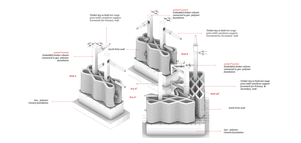
More detail on the wall to timber key support connections is shown below.
Risk Assessment and Construction progam
Because the first four printing days were straight loft prints, which involved less risk and required printing 20 layers, the necessary number of printing days was established for the risk assessment. However, we limited the number of layers printed each day to 15 as the risk rose.
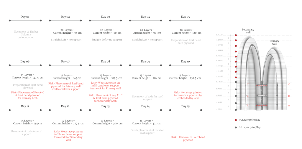
Risk increases starting on day 8 as the plywood supports are installed and as the keys needed to print the cantilevering portions have to be positioned on the lower level straight pieces. The removal of the keys and the kurfed plywood would be the last point of concern.
