
Introduction
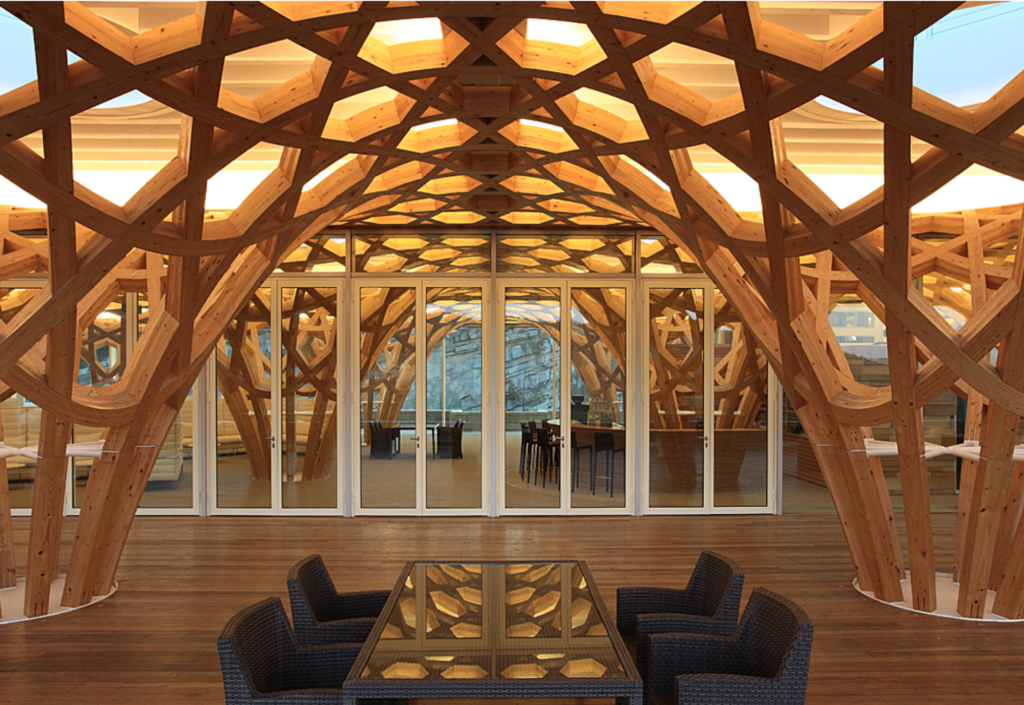
In our project, we analyze a timber gridshell characterized by the use of doubly curved laminated timber beams. Inspired by the design of the Haesley Nine Bridges Clubhouse, we have integrated advanced computational and optimization methods such as form-finding, structural analysis, and multi-objective optimization. Our aim is to achieve a harmonious balance between the natural beauty of the wood structure and its technical performance.
Formfinding
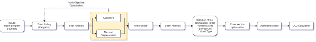
The initial values for the script are the architectural program in the form of arrangeable and size-adjustable circles, the number of supports, and a boundary frame. For the latter, it can be chosen whether it is rectangular or free-form.
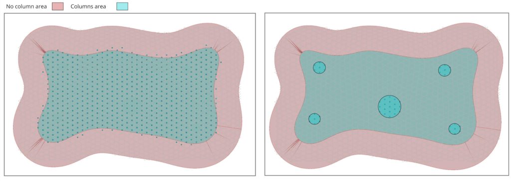
In the next step, these parameters are used to determine possible support positions. Then, using the Kangaroo components, a form-finding process is carried out based on these criteria.
Proofing
This geometry is then tested for its feasibility and implementability, taking into account two conditions.
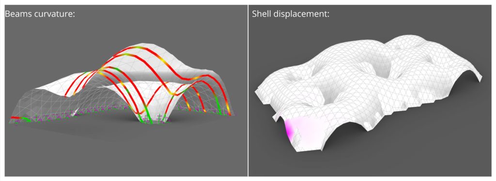
Firstly, the curvature of the laminated timber beams is checked using the Gluelamb plugin to see if it meets the requirements of Eurocode 5. It is stipulated that bent beams, depending on the laminate thickness, can only be executed up to a certain bending radius.
Secondly, an evaluation is carried out in Karamba3D. For this test, the geometry is simplified into a shell model. Details on the shell model will be discussed later. The highest deviations are then determined on this simplified model.
Multi-Objective Optimization
Due to the previously mentioned simplification to a shell model, these results could be obtained much faster than with a detailed beam model, albeit only qualitatively. This allowed for rapid iterations of the support positions to observe the associated effects. Using WallaceiX, a multi-objective optimization was carried out, optimizing the support positions in such a way that as many beams as possible meet the curvature criteria while simultaneously minimizing the maximum deflection.
Shell Analysis
Further analyses were carried out on the shell. The shell was analyzed according to second-order theory and checked for buckling. It was also interesting to observe the primary stresses of the first and second order.
To obtain reliable analysis values, it was necessary to set realistic boundary conditions. As a load, we assumed wind from one direction, as unilateral loads can have adverse effects on shells. Only the self-weight was considered as a vertical load. Other temporary loads were not taken into account, as a uniform vertical load tends to stabilize the shell before reaching the material limits – at least in most areas.
The choice of material turned out to be challenging. The Karamba material “Wood” was selected, which is defined as isotropic. However, we intend to construct the building from anisotropic laminated timber beams. Due to the very rigid connection in a triaxial composite between the beams, we assume that this assumption is correct. The material was assumed to be only 5 cm thick.
Overall, we assume that our assumptions should be significantly on the safe side.
Beam Model
The final optimized geometry was then transferred to a beam model. Here, special attention was paid to the definition of the bearing points to ensure optimal load distribution. A key aspect was the introduction of an “Edge Beam” at the openings of the structure. These Edge Beams play a crucial role in the stability of the shell construction, as they help to efficiently distribute loads around the openings and significantly reduce susceptibility to buckling.
Load Assumptions
With the more detailed beam model, it became necessary to use actual loads. These are composed of:
- Self-weight of the structure
- Self-weight of the roof – 2.5 kN/m²
- Live loads on the roof – 0.5 kN/m²
- Wind – 1 kN/m² pressure and 0.5 kN/m² suction
The calculation of the wind load on our very irregularly shaped building proved to be challenging. Therefore, we devised the following methodology:
Wind from the X-direction and wind from the Y-direction are assumed. For these two winds, it is determined which parts of the surfaces they hit first. These surfaces are then subjected to the wind pressure value. The remaining surfaces are subjected to a lower wind suction value.
All loads were then combined in a load case combination and provided with safety factors according to Eurocode 0. The combination was thus as follows:
1,35 * Self-weigths + 1.5 * (Liveloads + (Wind_X OR Wind_Y))
It should be noted that in the subsequent optimization, due to the OR operator, only the more unfavorable of the two wind loads is used.
Cross-Section Optimization
For the final determination of the cross-section dimensions, the “Optimize Cross Section” component of Karamba was used. This process determines the cross-section of each element in such a way that their load-bearing capacity is sufficient for all load cases.
By sorting the available cross-sections, specific optimization goals can be pursued. We implemented five cases that were of interest to us:
- Smallest Cross-Section: The cross-sections were sorted so that they are first arranged by cross-sectional area and then by strength class. The result is thus the smallest possible cross-section, even if this is achieved through very high strength.
- Lowest Cost: The strength values were associated with costs. A higher price was assumed for higher strengths, as the material must be accordingly tested and selected. The cross-sections were therefore sorted by cost per square meter. The optimization thus sometimes prefers a cross-section that is larger but has lower strength.
- Local Wood Species: The last optimization option offers the possibility to use three commonly found wood species in Turkey for the laminated timber beams. These trees are
- Libanese Cedar
- Black Pine
- Turkish Pine
To incorporate these trees, specific values were entered as new materials. Only the specific weight and Young’s modulus were adjusted. All strength values were adopted from laminated timber. This is based on the fact that all material values we found were determined under laboratory conditions on a small, ideal wood sample. However, actually processed construction wood will not reach these values.
CO2 Calculation
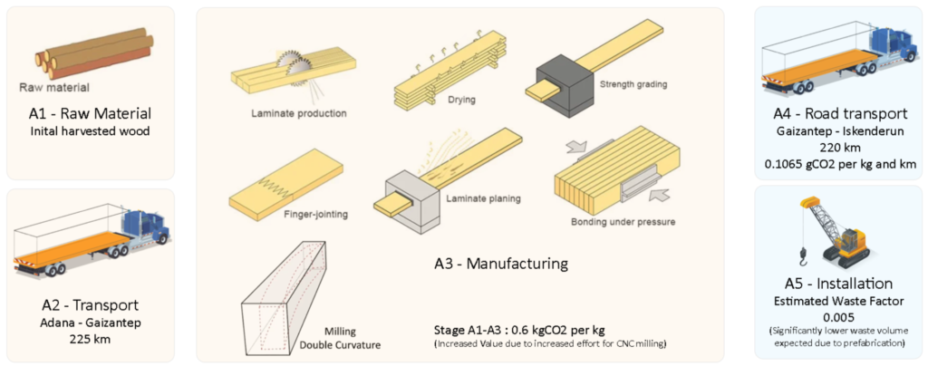
To compare the impacts of our optimization variants, we conducted a CO2 calculation following the principles of the Institution of Structural Engineers.
We determined the CO2 amounts for the wood structure in phases A1-A5.
We made adjustments in two aspects of the calculation. In phases A1-A3, we set a value for a significantly higher production factor than for normal laminated timber. The production of laminated timber beams with double curvature is extremely material-intensive due to the extensive use of milling. Some sources indicate that only 20% of the original raw material can be used as planned beams. We assumed the factor to be 50%.
Furthermore, we significantly reduced the waste factor in phase A5. Due to the aforementioned prefabrication, we expect that significantly less material will be wasted on the construction site.
Additionally, the floor slab of the project in Phase A1-A3 was calculated. For this, a reinforced concrete slab with a thickness of 30cm was estimated.
Lessons Learned
An interesting aspect of our project was observing how different optimization objectives impacted cross-sectional optimization and CO2 footprint. It was particularly interesting to see that the “Smallest Area” variant, targeting the least total weight, still achieved good CO2 values despite a high export distance. This underscores the importance of efficient material usage for sustainability.
Equally interesting, the CO2 emissions from the building’s floor slab far exceeded those of the timber structure. This highlights the environmental impact of different building materials and the necessity of integrating sustainability into every step of the construction process to reduce environmental impact and create more sustainable buildings.
Sources
- https://www.seccosistemi.com/de/projekte/haesley-nine-bridges-golf-clubhouse/ ↩︎
- Illustration Crane
Illustration Forest
Illustration Truck
Illustration Double Curved Glulam
Illustration Glulam Production Steps (edited) ↩︎
