During this one week workshop we explored the combination of stack lamination and 5 axis robotic milling for the speculative production of furniture for the new IAAC cafe. As a group we conceptualized and developed 3 items of furniture that could be produced using stack lamination. Each design was rationalized to make use of a single sheet of 2.4m x 1.2m plywood, this would inform how we would scale and nest each profile of the stack before moving the prototype to the Kuka.
Proposal 1
The curved bench acts as a continuous sweeping body through the perimeter and floorplan of the cafe. Creating micro spaces for communal gathering or individual work. The bench was split into sections of 50cm with vertical x-axis stacking arrangement, each module would be joined by a male and female connections.
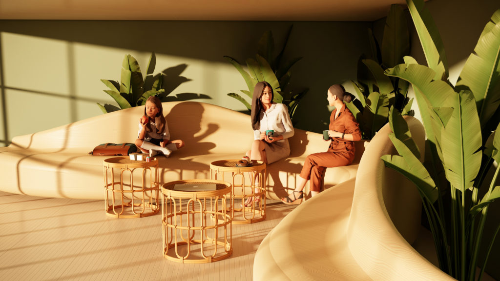
Figure 1 – Render Proposal 1
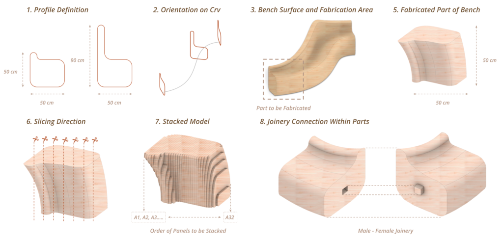
Figure 2 – Proposal 1 Creation and Fabrication Strategy
Figure 3 – 5 axis Milling Simulation for Proposal 1
Proposal 2
The cellular coffee table explores the mathematically informed assembly structure of a 3D voronoi. The body of the coffee table is made up of faceted cells that inform the overall body of the table. As a piece of production for this design only 1 cell of the table would have been produced. Orientation of the stack would be determined by whatever the largest face of each cell would be.
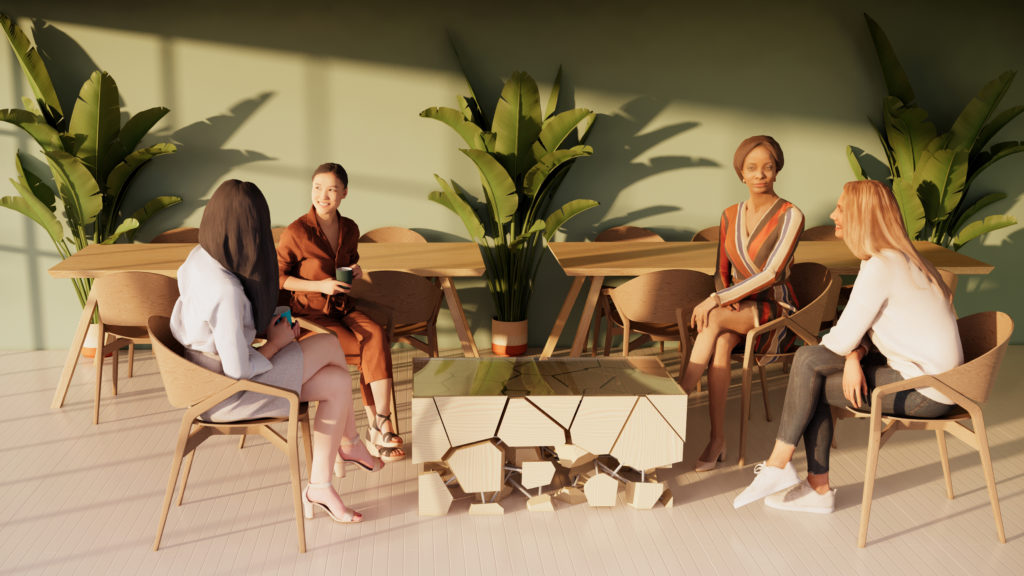
Figure 4 – Render Proposal 2
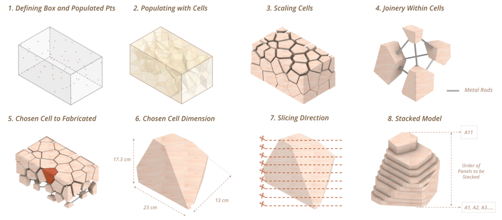
Figure 5 – Proposal 2 Creation and Fabrication Strategy
Figure 6 – 5 axis Milling Simulation for Proposal 1
Proposal 3 – Design Element Creation
Firmitas, utilitas, and venustas.
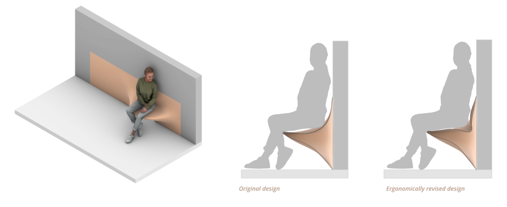
The design of a topographic chair makes use of simple forms that look as if they naturally sweep out from the wall. Consideration for the plywood stacking was done so as to create a typographic effect with the plywood layers. As the concept chosen for production we developed all aspects of the design as if it was actually going to be installed on site. The design element could be easily scalable and applied to multiple functions.
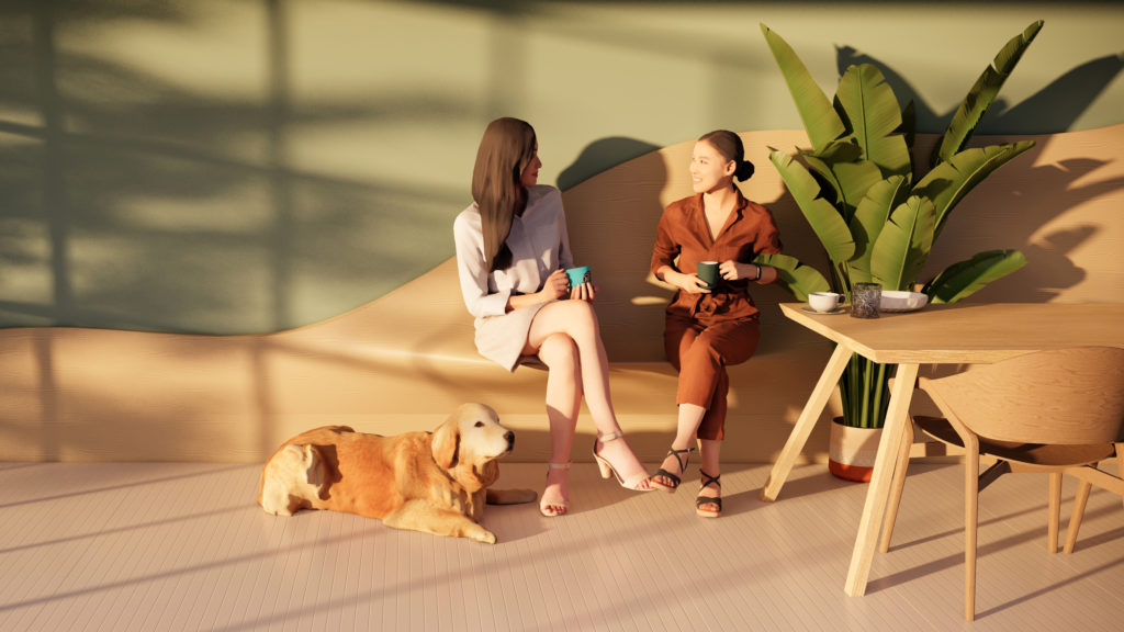
Figure 7 – Render Proposal 3
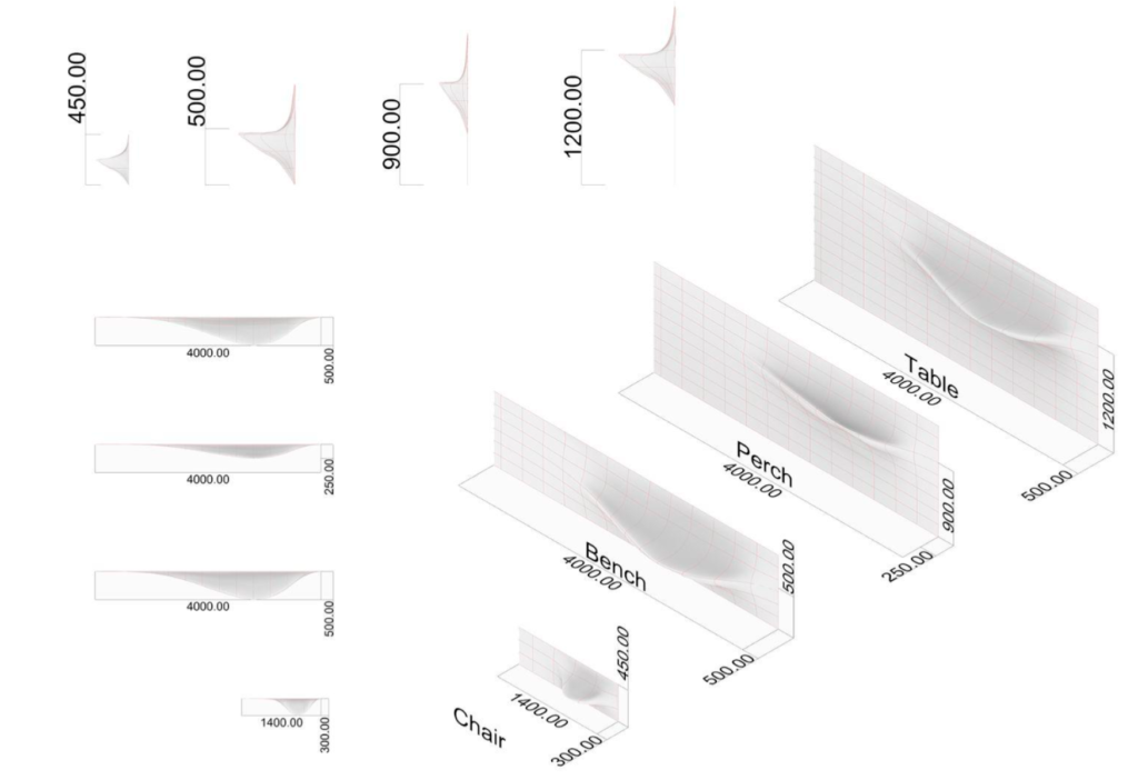
Figure 8 – Creation of Design Element
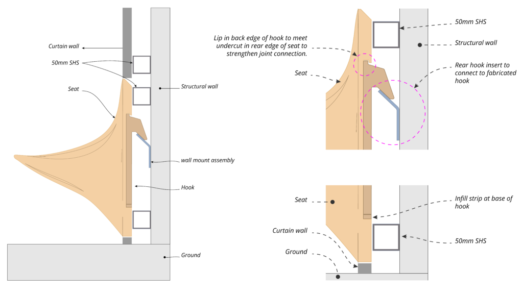
Figure 9 – Joinery System
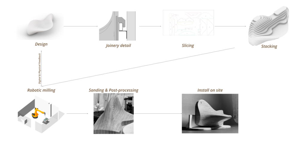
Figure 10 – Design and Fabrication Process
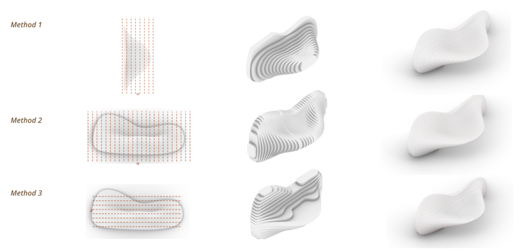
Figure 11 – Stacking Strategy
Proposal 3 – Fabrication Process
The design was scaled to a size that could be produced within the constraints of the robotic cell and available sheet size. Extracting the cutting path for the stacked panels was done by applying horizontal contour lines along the z axis of the design spaces 24mm apart to match the thickness of the plywood stock. From there we nested each contour shape to fit within the material boundary of the stock plywood panel.
After the stack panels were cut on the CNC, each panel was labeled, sanded and stacked using metal rods to locate each panelto each corresponding piece above and below, and bonded using timber adhesive. This process generated the rough model for the Kuka 5 axis milling & carving.
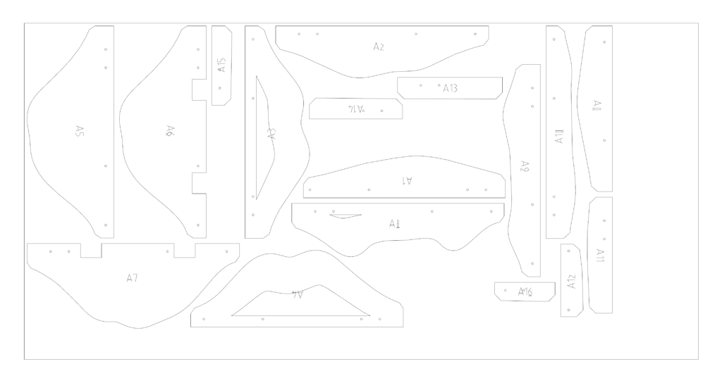
Figure 12 – Nesting Stacking Pieces on Plywood Board of 1.2×2.4m
Kuka 5 axis Milling
The relation between shape, fabrication method and machinery induced the fabrication process to be divided in 3 steps in order to avoid collision and enable a smooth sculpting process along the surface curvature, as an efficient usage of speed. Once the model was milled, it unveiled the wood grain and color, resembling topological curves, this effect happened due to stack lamination orientation. After milling, post-processing comprehends sanding, oiling and building a temporary stand to display the sample. A final and complete version of this model shall comprehend a substructure to enable assembly onto the wall .
Figure 13 – Dividing the 5 axis Milling Strategy
Figure 14 – Manufacture Process – From CNC to Robotic Milling
Final Product
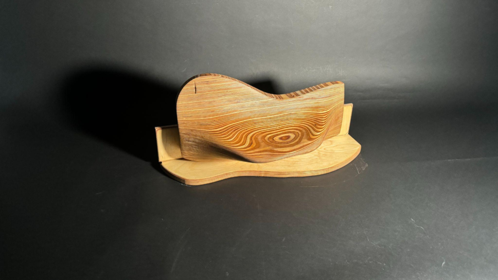
Figure 15 – Wood Grains direction on Final Bench
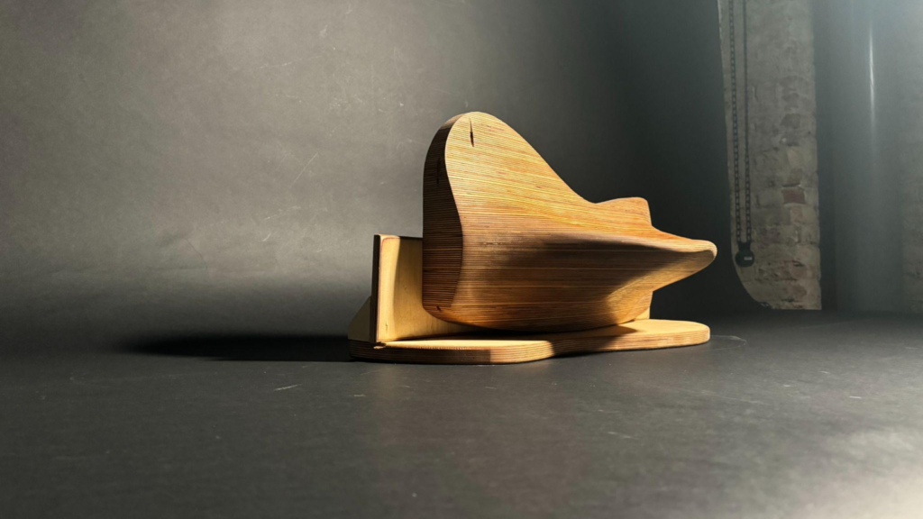
Figure 16 – Curvatures on side view from sitting part
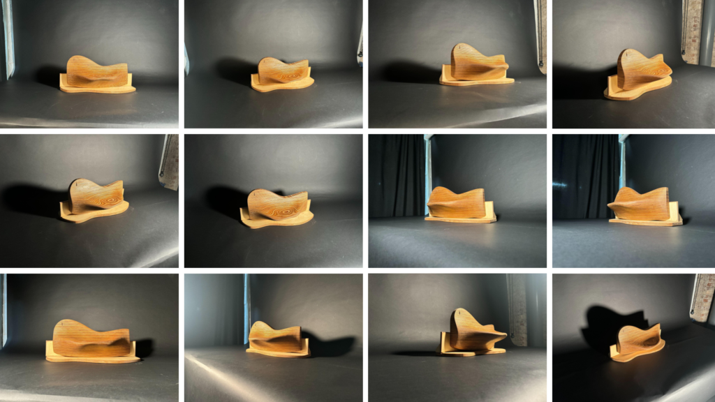
Figure 17 – Final Product from different angles
From Digital to Physical
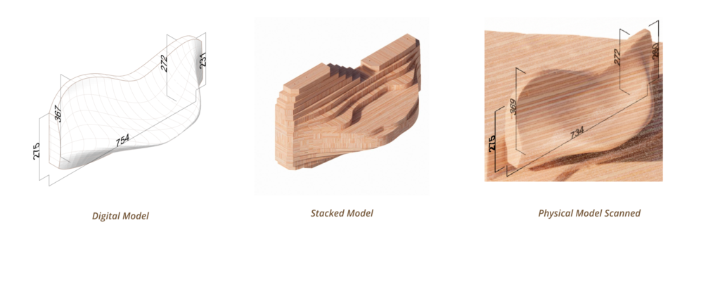
Figure 18 – From Digital to Physical Comparison
By comparing the digital model to the physical model some of the dimensions were did not matched the original model, this was due to various factors, such as: tolerance stacking, finished surface offset and precision of scanning hardware/ software.
Further Steps
Taking the opportunity to critically reflect on our work over the past week these are some of the design changes that we would have liked to develop if given the opportunity to make a second version of the prototype.
Scaling up
Producing a 1:1 model ment we had to rethink how the robotic cell can accommodate a piece of this size.
Our proposal for this is to have a robot on a track so to extend the reach of the robotic arm.
Figure 19 – Design and Manufacturing – Scaling the product
Robotic Pick & Place
In the scenario where we will have to scale up production of our design we implemented a robotic pick and place program – this would remove the need for a dowel connection when gluing the piece together as the robot could accurately stack each panel directly from the CNC bed with enough accuracy before clamping and milling.
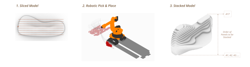
Figure 20 – Robotic Pick and Place for Stacking Process
Material and stacking development
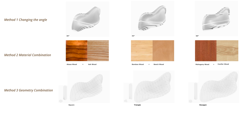
Figure 21 – Different Stacking Strategies
Ergonomics
More consideration of human form and ergonomics in the design of the chair.