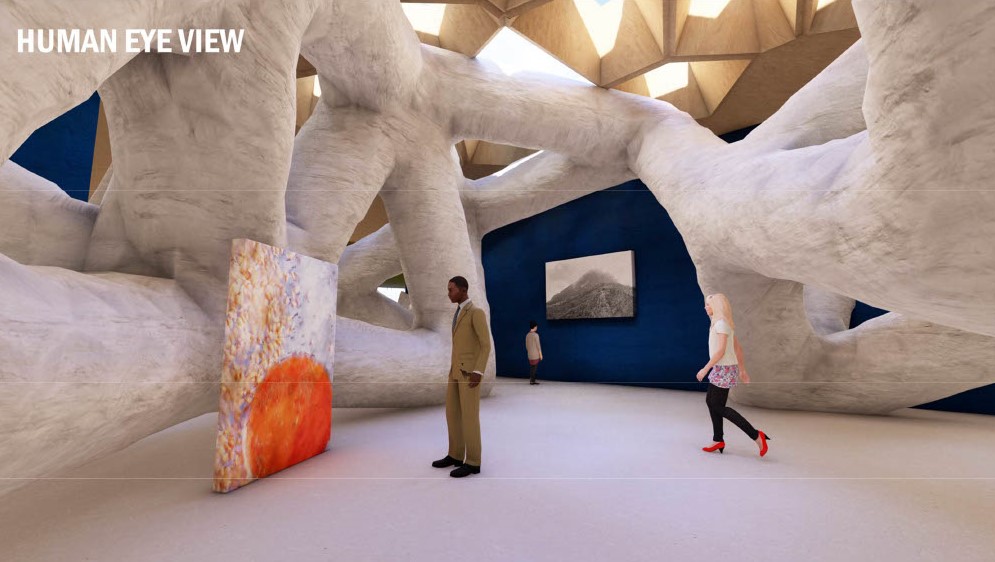
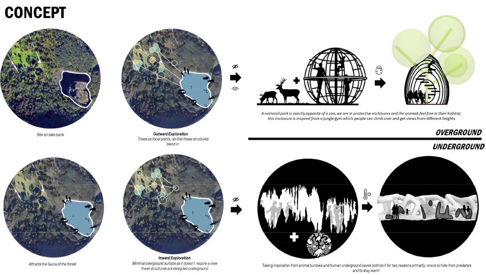
The site is located on the banks of the water body. We developed a design in two parts for outdoor exploration—the museum. We designed structures with trees as focal points so that they blend in with their surroundings. They are expanding on the concept of a natural sanctuary. Where humans are in jungle gym like enclosures. Dinosaur eggs inspired the design of these enclosures, which are for the areas that do not require views. These programs were designed underground. They are taking inspiration from animal burrows and underground caves. The alleys were designed like cave-like tunnel galleries. Which also helps to keep warm in these cold climates.
For our overground workflow, we started with a mathematical equation. And then we started to manipulate this. And also, by adding and subtracting with this, we obtained some iso curves. Moreover, we started to rotate these curves. We went two ways, as we can see. Then, we created openings for the tree branches. For this, we also converted these into curves to obtain these lines. For the final part, we added some stairs to create a view tower or to give access to the underground.
For our underground exploration, we identified the volume based on trees as focal points. Then, we populated the volume with points and connected them in four ways. Then, we established the parts of movements that would be our galleried alleyways—moreover, we generated the volume. Then, we trimmed the volume under the grid shells and in our interior spaces. We identified where the geometry meets the ground surface, the geometry, and our walls. So that the rest of the area could be populated by boronoid for daylight. We then modulated the openings of foreign oil. To achieve an adequate daylight factor.

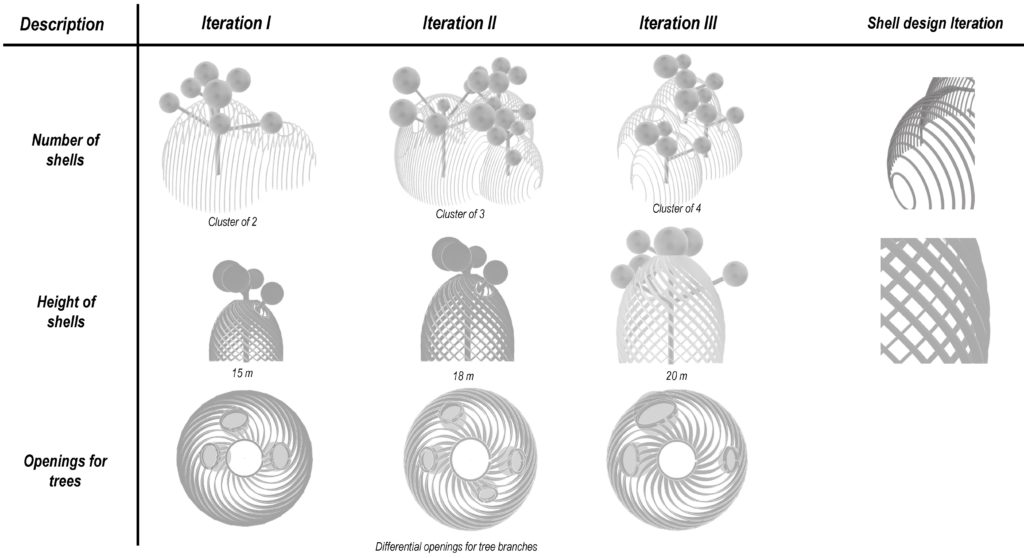
Our form iteration for the grid shells depends on various variables. First, one was the number of shells. Depending on if each location has a cluster of trees. These would also be a cluster of grid shells. The height was a critical factor. Especially for the ones that are located in the back. To have a nice view of the lake. Each grid shell would have a different opening depending on the tree branches. We also went with some vertical lines and some curvature lines for the design. For a form finding, especially for the grid shell’s height, it depends on how these have a good view of the lake. So, with Isovis, we analyzed which grid shell would be the most optimal for this and what height it would have as we can see in figure 4.
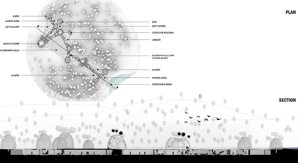
In our plan. What we can see that the design has been formulated such that the shells are at the entry as well as at the exit with tunnel galleries. Provides circulation parts between the screening halls, library, and other auxiliary spaces, with the large shell also acting as an outdoor dining area near the lake. This section shows how these tunnels are connected to each grid shell and the experience it would create with its distinctive form. This is the plan view of the entire structure.