ARCHITECTURAL CONCEPT
DECOMPOSITION | TOP DOWN APPROACH
FUNCTIONS
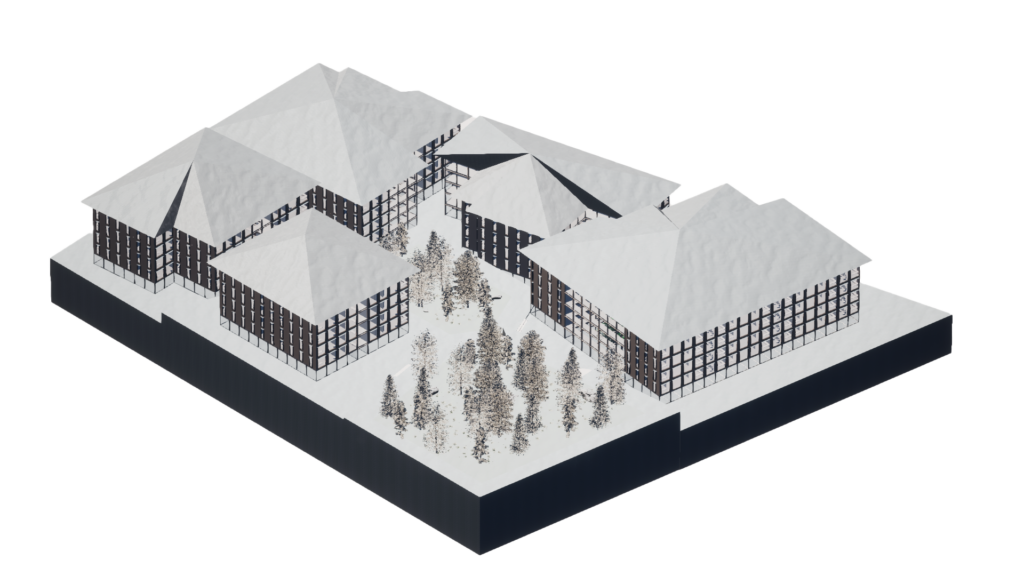
We have followed a top down approach for the creation of an algorithm that creates buildings that adapt to different climates and serve mostly to residential use. The algorithm starts dividing the plot into subplots using an optimized Voronoi segmentation, which are then arrayed and scaled in the z direction. A grid is then used to rationalize the shape of the buildings and populate the different apartment types. The program mainly consists of residential space except for the ground floor where parking, commercial and communal spaces are created. The circulation to and from each apartment unit occurs through hallways located in the centered atrium, which depending to the location, shall be enclosed or open to the climate. The style of the created buildings represent a language of terraces to offer the inhabitants the possibility to connect to their surroundings.
STRUCTURAL FE MODEL
The geometry of the buildings is decomposed into first a 2-dimensional grid of beams and then into a 3-dimensional grid of beams and columns. The 2D grid size is 6m x 3m and the height is variable depending on the climate, either 3m or 4m. Floors and balconies are placed on the structure while slabs and mainly bracings ensure the stability of the building. This decision has been made to offer great flexibility and to allow the reorganization of apartment sizes according to whichever need for new living typologies arises in the future. All structural elements are directly derived from the algorithm that creates the buildings.
STRUCTURAL DIAGRAMS
As illustrated above, vertical loads are transported through the columns while lateral forces such as wind are dissipated through the bracing elements, for x and y axis. The combination of this elements intends to generate a stable shape, aimed to be modular and pre – fabricated in the material that suits the project’s location better. The floor spans in the shortest direction of 3m, giving us a guideline for the distribution of main and secondary beams afterwards.
OPTIMIZATION | WORKFLOW

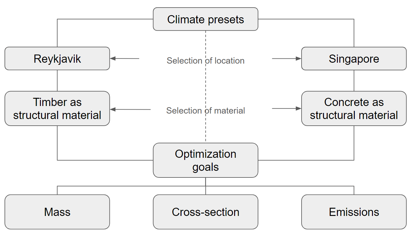
We have developed two different structural systems based on two different climates: for Reykjavik we decided to use timber. For Singapore instead we will be using concrete. The main optimization goals were: minimize the mass and the cross-section of the elements and by doing so also the CO2-Emissions of the structure.
OPTIMIZATION | EXPLORATIONS
TIMBER AS STRUCTURAL MATERIAL

CONCRETE AS STRUCTURAL MATERIAL
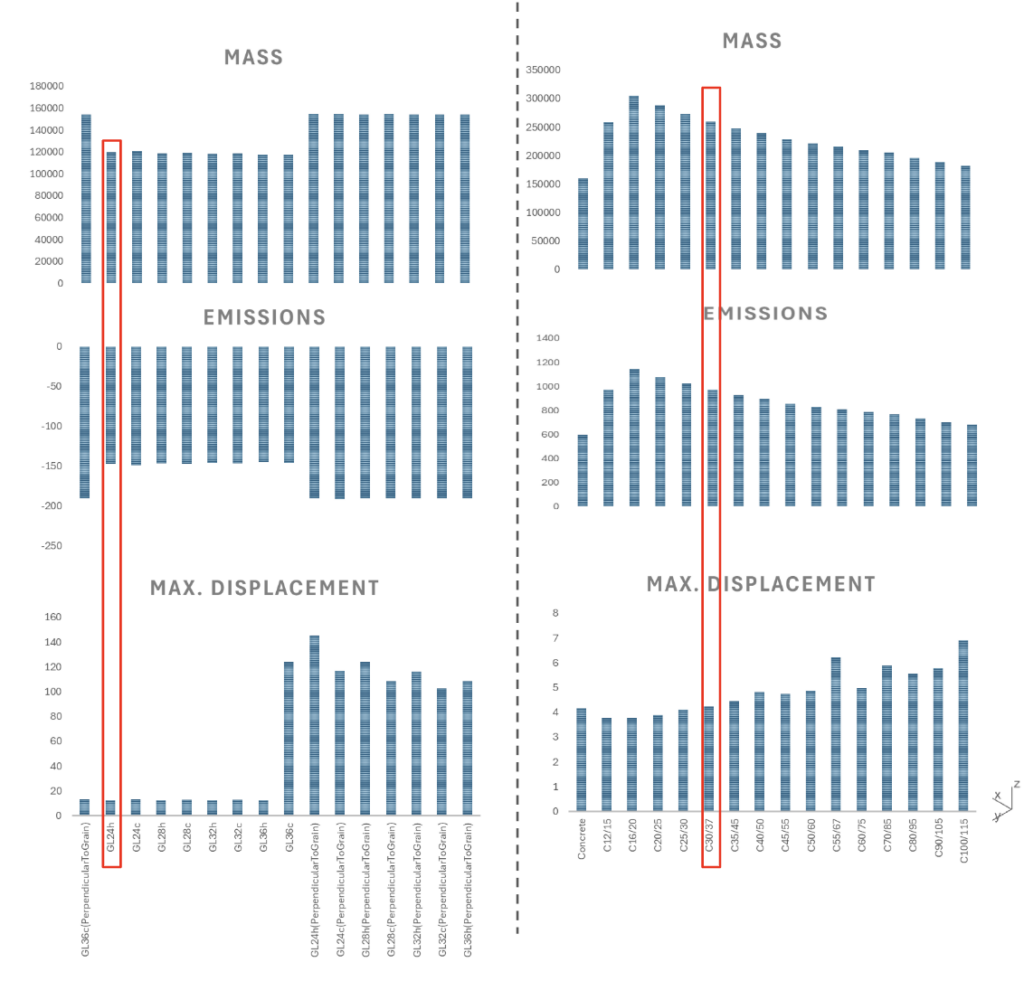
We investigated Multiple material options inside the timber Glulam family for Reykjavik as different concrete types inside the concrete family for Singapore. Among the various options investigated, we chose the timber Glulam GL24 and for concrete C30/37.
OPTIMIZATION | RESULTS
TIMBER AS STRUCTURAL MATERIAL
Columns: 40×40
Primary beams: 20×40
Secondary beams: 15×30
Balcony beams: 20×40
CONCRETE AS STRUCTURAL MATERIAL
Columns: 22×22
Primary beams: 20×25
Secondary beams: 15×20
Balcony beams: 15×30
Lastly, Here we can see how the different components have been optimized to achieve the previous goals. For instance for the concrete structure, columns have been dimensioned with 22×22 cm, primary beams with 20x25cm, secondary beams with 15x20cm and lastly balcony beams with 15×30. This represents the optimized outcome of the process.

