
Introduction to Robotic Operating Systems
Github repository: https://github.com/sashakraeva/MRAC-ur-perception
Introduction
his course provided a thorough introduction to the Robot Operating System (ROS), teaching us essential skills in robotic software development. We learned about key ROS concepts like nodes, topics, messages, and services. Using robotic perception as case studies, we understood how ROS connected robots, sensors, and other hardware. By the end of the course, we explored how perception data could influence the design-to-fabrication workflow.
Skills acquired include:
- ROS Fundamentals, including its architecture, and its role in robotics and communication between hardware systems.
- Work with ROS Tools, including data visualization, nodes, graphs, and simulations.
- Practical experience working with robotic manipulators + perception systems to apply ROS concepts in real-world scenarios.
Obscured Object Tracking Exercise
Objectives
The exercise challenges each group to complete the following objectives:
01. Extract fabrication data using 3D sensing (e.g., point clouds, meshes, or transforms).
02. Perform analysis on the extracted data. Students are encouraged to integrate other software tools (such as Rhino, Grasshopper, CloudCompare etc. )for this purpose.
03. Demonstrate how the analyzed data will be utilized in the workflow through simulations.
Project Overview
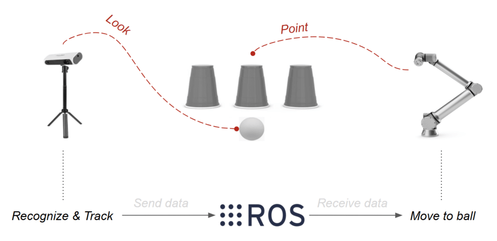
“Guess the Cup,” a timeless carnival game, invites the patron to track a ball as it shuffled under one of three identicle cups. Once the cups are shuffled, the patron is invited to point to the cup that they believe is holding the obscured ball. If the patron guesses correctly, the obscured ball is revealed when the selected cup is lifted.
In our investigation, a 3D camera replaces the patron’s perception and the robotic arm replaces the patron’s arm. A laptop equiped with ROS Noetic is used to merge all the functions between the equipment. In other words, the challengs is to collect, process, and analyze spatial data to inform robotic operations.
Hardware

Strategy
- Step 01. Extract fabrication data from 3D sensing
Foremost, the team opted to use the Azure Kinect 3d camera equiped with Intertial Measurement Unit (IMU) to ensure enhanced motion tracking, among its other capabilities– color and depth detection, and compatability with ROS and deep learning frameworks. The camera remained fixed, using a frame extraction to collect the raw image data.
- Step 02. Perform analysis on the extracted data with integrated software tools.
Altough YOLO (You Only Look Once) real time object detection tracking system was initially used to identify the ball and cups in motion, OpenCV was ultimately best for distinguish the ball and cups based with RGB color and contour detection. Each object was then masked and assigned an identification for tracking. The mask was then transfered from 2D to 3D point cloud detection for tracking in motion.
- Step 03. Demonstrate how the analyzed data will be utilized in the workflow through simulations.
Pseudocode


To manage multiple processes, Terminator is launched. Inside a new window, the ROS Master is initialized with roscore, setting up communication between nodes. The robotic system starts with roslaunch in order to set the camera and the robot driver. Individual nodes can be executed using rosrun. Nodes handling RGB images and Point Cloud Data (PCD) are listed with rosnode list, and their details are checked with rosnode info. These nodes process data using Python scripts, OpenCV, and YOLOv5 inside the Docker container. Active ROS topics are monitored with rostopic list, showing /points, /rgb_raw_image, /rgb_mask, /filtered_points, and /tcp. Additional details on specific topics can be accessed using rostopic echo.
Data Flow Diagrams

The diagram represents a basic workflow transitioning from a remote environment to a local environment, where data flows from a physical setup to a digital system running inside a Docker-based ROS environment.
The remote environment, represented by the yellow section, is where the process begins. A repository (REPO_NAME) is forked from an individual account to a group account on GitHub. This forked repository is then cloned into the local environment, creating a working copy that sets up a Docker-based ROS environment on a local machine.
The local environment, enclosed in the blue section, is where the system is deployed. Within this environment, a ROS node runs inside Docker and manages communication between different components. The node publishes and subscribes to a Point Cloud Topic, which is visualized in RViz. RViz, in turn, subscribes to this ROS topic to display the point cloud data and can also publish configuration changes back to the ROS node. Additionally, RViz communicates with a Universal Robotic Arm, enabling real-time interaction between the digital and physical worlds.
Inside the local environment, two distinct sections are defined. The digital environment, represented by the black section, is where Point Cloud Data (PCD) is processed and visualized in RViz. This allows users to interpret depth and object positions based on real-world input. The physical environment, shown in green, consists of a real-world setup where three cups and a ball provide data to a camera. The camera publishes RGB, depth, and point cloud data to the Docker-based ROS system, allowing the ROS node to subscribe to and process this information.
This workflow demonstrates how data from a physical environment is captured, processed, and visualized in a digital system using ROS and Docker, enabling interaction with robotic systems like a Universal Robot arm.

This diagram illustrates a ROS 1 system where Terminator plays a crucial role in managing multiple ROS processes efficiently. The workflow is designed to handle robotic operations and computer vision tasks through a structured pipeline, utilizing Docker, ROS, and OpenCV within a well-organized workspace.
At the core of the setup is the terminal environment, where Terminator is used to run multiple ROS commands in parallel. Instead of managing ROS nodes and topics in separate terminal windows, Terminator enables users to launch, monitor, and debug processes within a single, organized interface. This is particularly useful for handling roscore, roslaunch commands, and topic monitoring via rostopic list. Details about the communication between the nodes have also been depicted in a previous diagram. In this case more focus is given to the presentation of the connectivity between tools and environments like the terminal, the terminator and the Docker-based ROS environment.
Terminator, a ROS network is structured around several interconnected nodes. The master node (roscore) orchestrates communication, ensuring that all topics and services are properly registered. Inside the red section the roslaunch commands are shown with the images of the camera and the robotic arm, The topics are also shown vertically with points, rgb and tcp being the main categories. The Nodes (rosnode)are also shown vertically with bigger black circles. The black arrows represent the publish between the icons and the white arrows the subscriptions.
To maintain an isolated and reproducible ROS environment, a Docker image is built using a Dockerfile. This containerized system houses the ros1_workspace including source code (SRC), built packages (BUILD), and development resources (DEVEL). OpenCV is integrated into this workspace, enabling advanced image processing inside the ROS pipeline. In this project more focus was given to the scripts inside the package which included the python,Open CV and the Yolov5.
Once modifications are complete, the workflow loops back to GitHub. Changes are staged with git add ., committed using git commit -m “Updated ROS nodes and scripts”, and pushed back with git push, ensuring all progress is saved.
Challenges
- YOLO did not properly identify the masked cups once standardorientation was inverted.
- Tracking was lost when masked cups where obscured by adjacent and identical masked cups. The majority of the cups’ contour needed to remain visible and unblocked for consistent detection.
- Changes in daylight effected the RGB detection from trial to trial, so the color range detected needed to be adjusted for each trial.
- For future trials, tracking systems like Kalman Filters may be more effective for consistent tracking of moving and similar objects.
Conclusions
In conclusion, this course has provided a comprehensive foundation in the Robot Operating System (ROS) and its application in real-world robotic systems. We gained a deep understanding of key ROS concepts, such as nodes, topics, messages, and services, which are essential for effective communication within robotic environments. Through hands-on experience with tools like RViz, OpenCV, and simulation frameworks, we successfully applied these concepts to real-time robotic systems, particularly in the context of perception and fabrication workflows.
The “Guess the Cup” exercise presented unique challenges that allowed us to integrate 3D sensing, data analysis, and robotic control. By leveraging the Azure Kinect camera and advanced software tools, we were able to track and process data to inform robotic actions, demonstrating the power of ROS in combining hardware and software. Although we encountered some challenges, including issues with object detection and tracking under changing conditions, these experiences provided valuable learning opportunities for troubleshooting and refining systems in dynamic environments.
Overall, the course equipped us with critical skills in robotic software development, from understanding ROS architecture to implementing complex perception tasks. These skills will be indispensable as we continue to explore and develop innovative robotic applications in the future.
