
Computational Design for Digital and Robotic Fabrication
Introduction
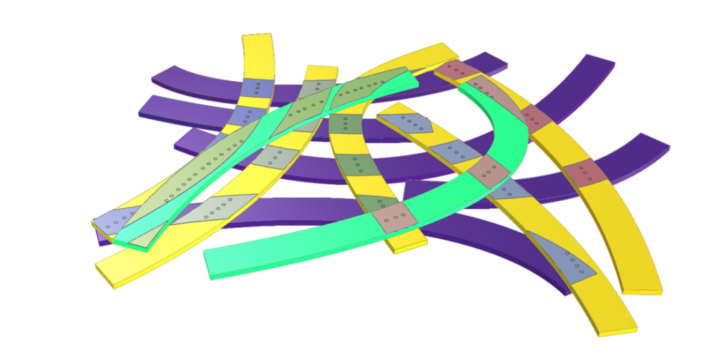
The Software I module served as our introduction to understanding how designs produced on the computer translate into fabrication strategies that can be used by a robotic arms in various ways. The seminar was broken up into four exercises, each exercise involved a specific robotic operation and we would then go through the strategy of how a specific operation relates to a manufacturing strategy. All four exercises were done on grasshopper and we ran simulations in grasshopper as a means to validate and visualize the methodologies.
The four operations that we looked at are:
- Advanced Toolpath Design for FDM 3D Printing
- Design for Manufacturing of 3D Printed Architectural Systems
- Design for Manufacturing of Complex Structures From Standard Elements through Robotic Manipulation Processes
- Design for Manufacturing of Interior Design Systems Enabled by Advanced Robotic Milling
Advanced Toolpath Design for FDM 3D Printing
Overview:
This exercise revolved around designing a toolpath strategy for FDM 3D Printing. FDM (Fused Deposition Modeling) works by heating a material until it is molten and depositing the material in layers, the molten layers fuse and as they cool harden into a material. Traditionally this is achieved through planar 3D printing which uses 3 axes to deposit the material in even orthogonal layers. This method can produce high resolution results and is ideal for small objects, however it’s short comings are compounded in larger prints, namely the slow print time is exacerbate the more material that needs to be printed. Further more defects in the print layer can appear due to a high number of retractions.
The solution that we used to work around this problem is to use a continuous toolpath movement. This allows for variations in layer width and depth, this is specifically relevant when the printed object utilizes organic forms with varying curvature across the form.
Fabrication Strategy:
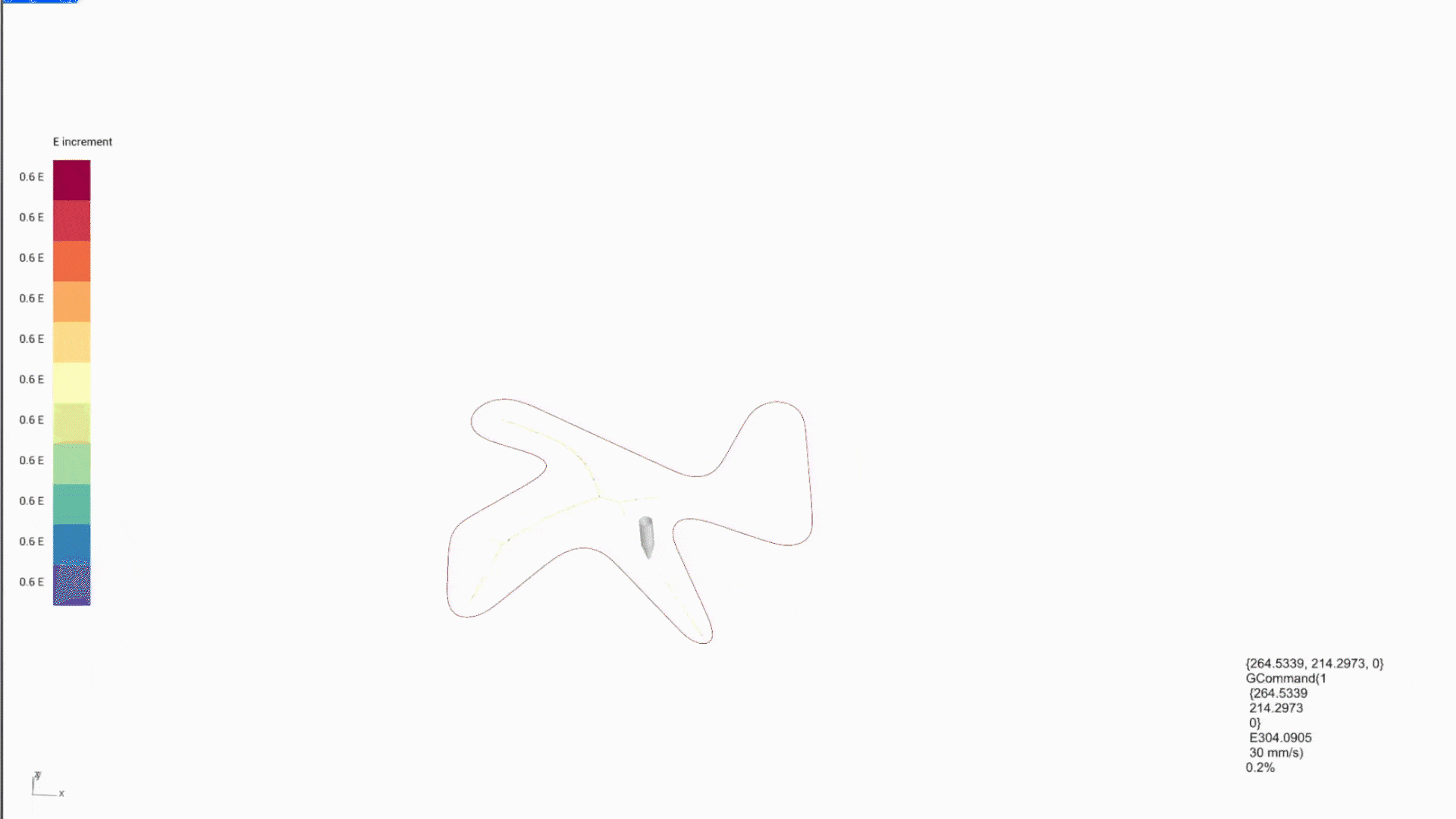
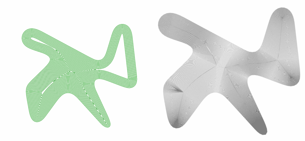
- We started with a “vase-like” structure.
- The Surface was divided into curves. The number of curves were determined by the maximum layer height of 2mm.
- The curves were exploded into points. These points were incrementally offset to the next layer, creating a continuous spiral curve.
- A base was constructed separately using two printing layers.
- These separated curves were joined into a singular toolpath.
- The last thing that needed to be accounted for was the variable layer height which is controlled by the E-Value in 3D printing.
- By having a variable E-Value different layer thicknesses can be printed adjusting for the increased curvature in the wall.
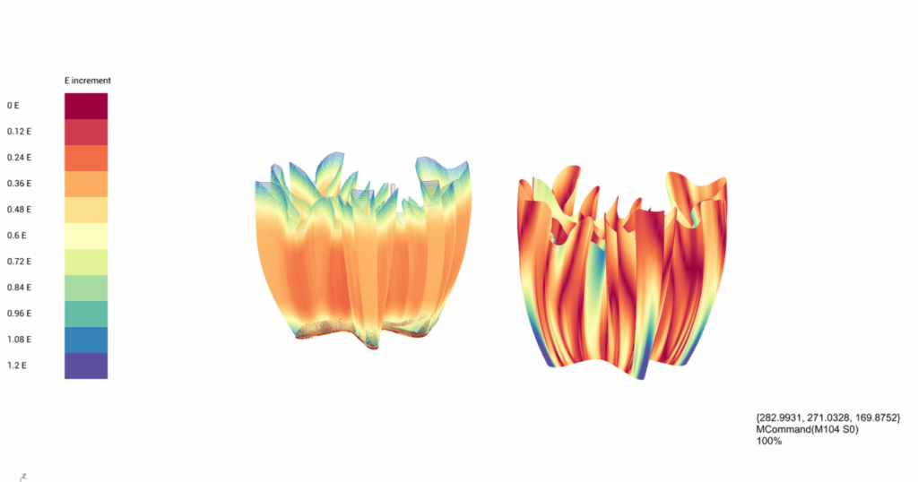
Optimization:
The original script for the base layers was not ideal for forms with drastically undulating edges. Thus this led to the presence of large gaps. We opted to create a different toolpath strategy that was designed around the skeleton of the base. This new toolpath resulted in a much tighter print with much fewer gaps.
Shortcomings:
The toolpath for the base layer had to be manually optimized, ideally the script should be of such a nature that any shape base should result in continuous curves without the necessity for manual manipulation.
Design for Manufacturing of 3D Printed Architectural Systems
Overview:
This exercise lies in the intersection of 3D printing, prefabrication and modular construction. This type of construction involves taking a large complex from, breaking it up into manageable modules and 3D printing these modules for later assembly on site. The advantage of this process is that it allows for the printing to take place off site in controlled conditions. It also has a built in redundancy, as if any part of the print goes wrong or if a single module were to be damaged, only that module needs to be replaced. The material that we simulated for this exercise was clay, clay is interesting as a material because of it’s plasticity and variable shrinkage. Depending on the mixture clay can have as much as 5-10% shrinkage during drying and if it is fired for ceramics a further 5-10% shrinkage can occur. Thus the form of the modules needs to be conducive to the stresses caused by shrinkage.

Fabrication Strategy:
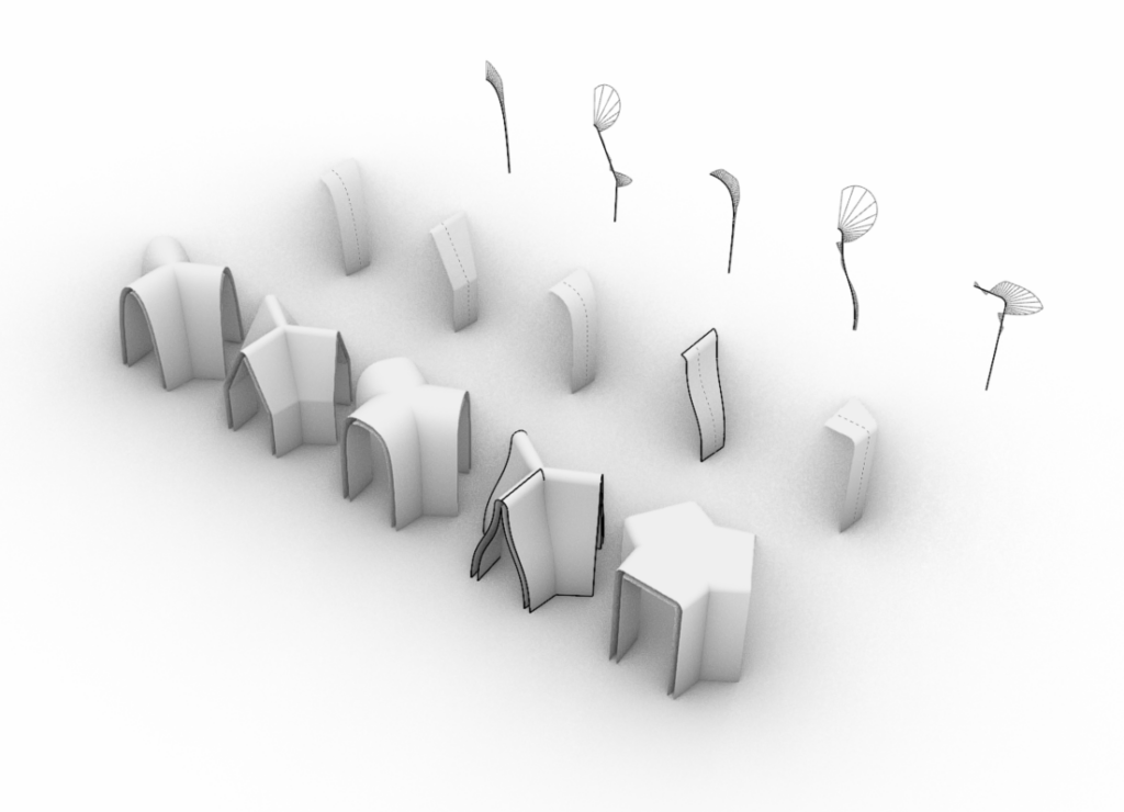
- We were provided with 4 pavilions to choose from
- Each pavilion is comprised of a single panel which is mirrored and arrayed along three points at 120° intervals.
- The panel is then subdivided into modules. The subdivisions are limited by the print angle and height of the module, 30° and 500mm respectively.
- Next an infill pattern is created, which is integral to the stability of the modules.
- An offset is then applied to the infill patterns to account for overlap of extrusion material. the maximum allowable amount is 50%.
- The modules are then arranged for printing using a nesting strategy. In our case this was optimized for pallets
Optimization:
The original script was optimized for gradual curves with large radii. This caused major issues with our selected pavilion as the print angles and cantilevers meant that the modules were unprintable. We changed the segmentation strategy to be based off the normal of the curves at 20 points along the curve length. The script then segments at the point of maximum curvature. Allowing for lower print angles and shorter modules.
Shortcomings:
There were two shortcomings that we identified. The primary one is that regardless of segmentations optimization of the modules the top most modules that made of the coping of the panel continued to be unprintable. Thus in order to produce them the printing toolpath strategy would have to be rethought.
The second shortcoming is the nesting strategy that we used. Although printing directly onto pallets optimizes for transport and minimizes the chances of breaking a module when moving it. Re-arranging the pallets so that more than one can be printed at a time will decrease the print time dramatically.
Design for Manufacturing of Complex Structures From Standard Elements through Robotic Manipulation Processes
Overview:
This exercise involves an operation colloquially referred to as pick and place. Pick and place requires an assembled geometry to be understood sequentially. In this way a stock of material is manipulated by the robot and put in place. Additional processes can be added to this, such as in the case of the operations we looked at, nailing. This allows for the precise assembly of large objects from smaller modules, such as truss construction.
Fabrication Strategy:
- We started with an assembly based off of a documented library of materials: wooden planks.
- The planks in the assembly are organized in a list based off their z value (bottom to top). This will determine placing order.
- Next the overlapping zones between two planks is calculated and the nailing lines of these overlaps are determined.
- The nailing points are optimized to ensure that they are not close to the edge and two nails are never on top of each other.
- Next a picking plain is determined, from which the wood planks will be picked up.
- The point at which planks are picked up are aligned to nailing points.
- Effectively, the robotic arm picks up a planks, positions it in place creating a base layer.
- The next layer of planks are placed and nailed down, after this the arm lifts off and nails the remaining points.
- this process repeats until the assembly is completed.
Optimization:
The original pick and place script only worked with rectilinear elements. It would misalign the vacuum cups for picking up the planks. Thus we changed the alignment strategy to account for curved elements.
Shortcomings:
Our current script only works with planar assemblies. Thus if elements vary along the z-axis or we want to assemble elements across layers, it isn’t possible.
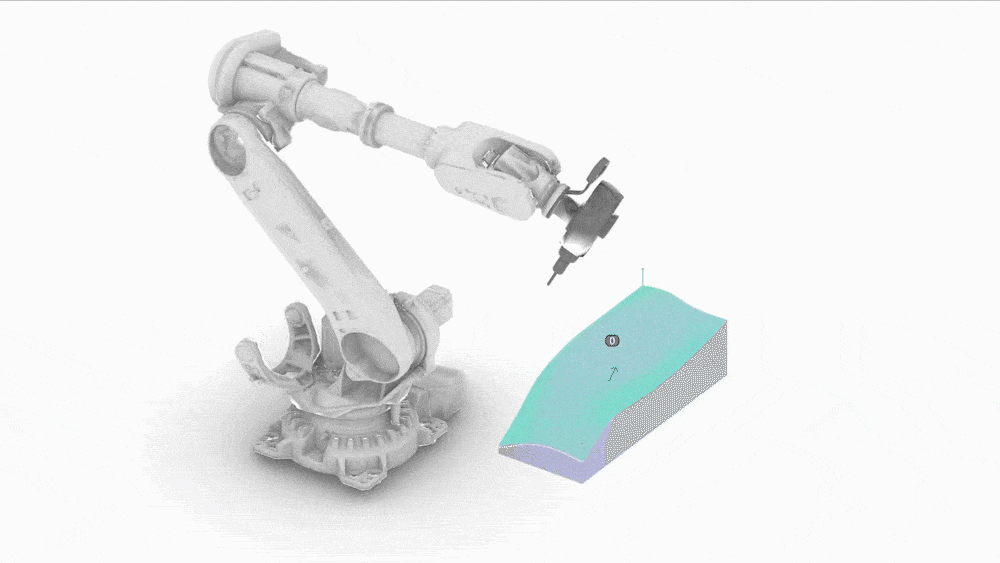
Design for Manufacturing of Interior Design Systems Enabled by Advanced Robotic Milling
Overview:
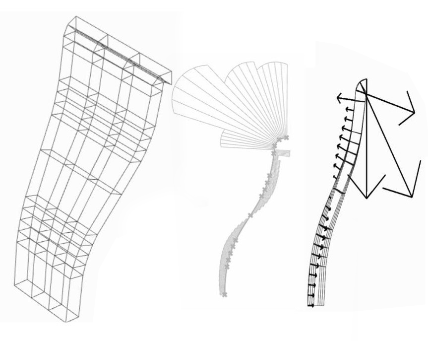
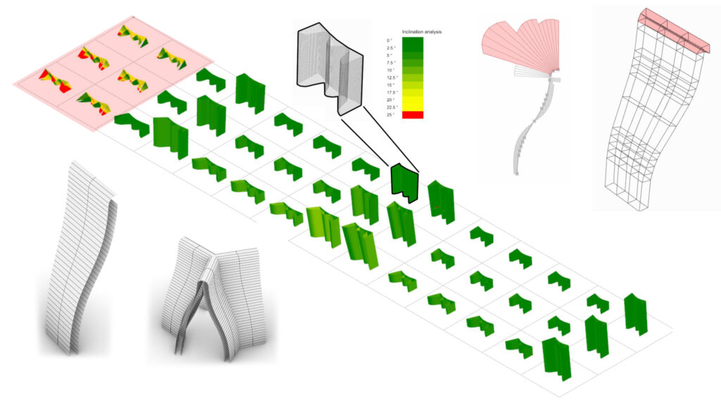
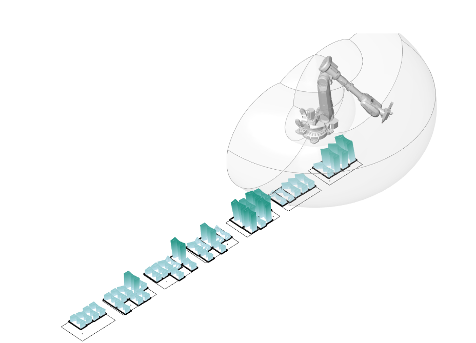
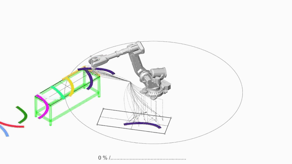
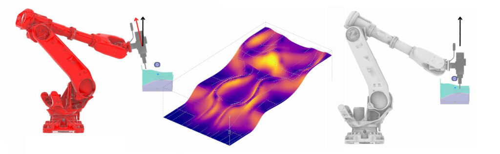
In the final exercise we looked at creating a large organic curved surface using subtractive manufacturing. Specifically we used two different subtractive manufacturing methods. We used wire cutting and milling. Both of these operations served different purposes. The wire cutting operation is used for roughing the material, which essentially means getting it as close to the final form as possible. Milling allows for a fine, highly accurate finish. Milling and wire cutting have entirely different functional characteristics and thus have vastly different toolpath strategies that need to be employed. thus when using these two methods in conjunction two different approaches need to be taken in the input geometries.
Fabrication Strategy:
- We started with a large organic geometry.
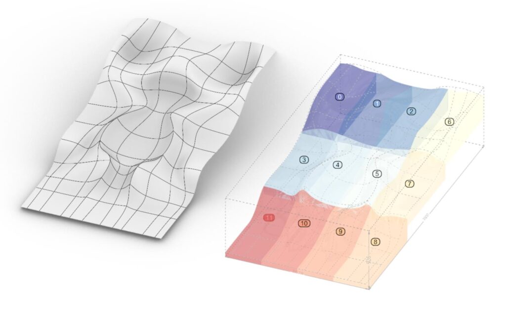
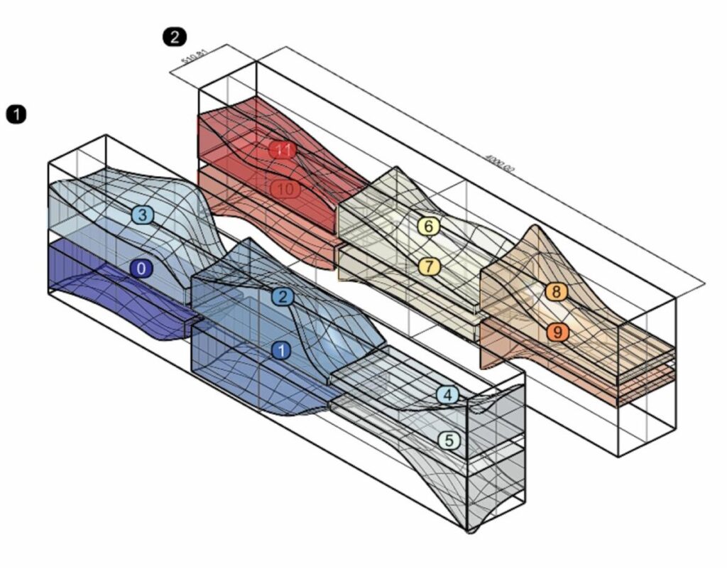
- The surface is then sliced up into pieces that are nested into blocks of EPP (expanded polypropylene) foam.
- The wire cutting surface is based off the closest surface that can be achieved by wire cutting.
- Wire cutting needs to be based off of a ruled surface, thus the offset face needs to be changed into a ruled surface.
- The ruled surface is sliced perpendicular to the path that the wire cutter takes, and the center points determine it’s path of travel.
- The milling is divided into two parts, roughing and finishing.
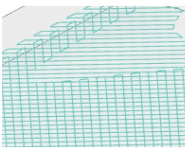
- The milling roughing procedure is based of a contoured surface and steps between contours lines, like a pyramid.
- For finishing, the milled surface is divided along the widest curve on the surface perpendicular to the planned toolpath, this is to ensure sufficient step over.
- The list of points that define the milling toolpath are reversed every second line in order to create a snaking motion, this reduces tool path time and safe plane movement.
Optimization:
We rotated the wire cutting surface 90° in order to stop collisions between the wire cutting tool and the robotic arm.
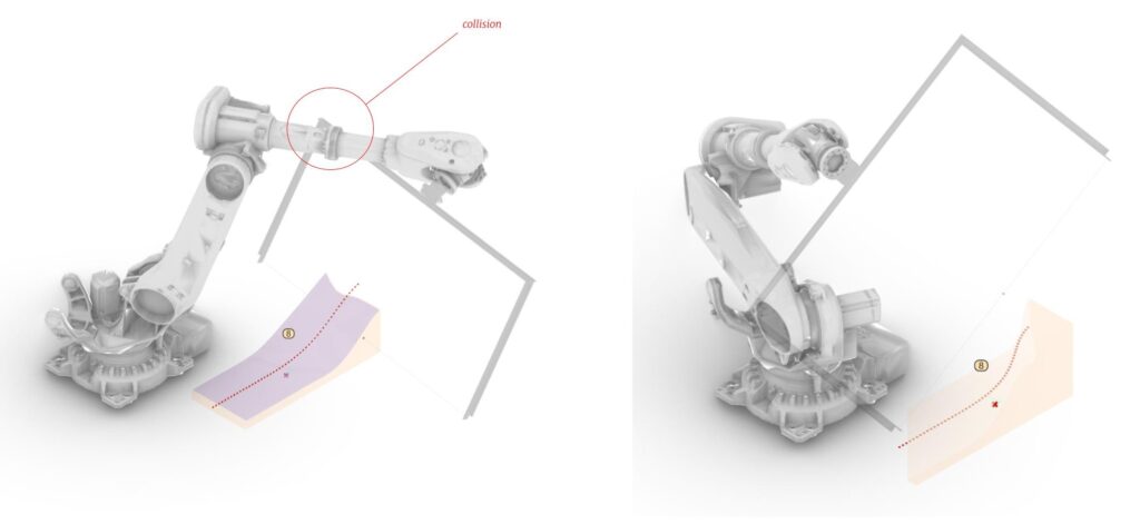
Additionally because of the curvature of the object, if we mill along the normal of the object, robotic joints can lock up. Thus we fixed the milling along the z-axis to avoid this problem.
Milling lines during the roughing procedure rotates by 90 degrees from layer to layer to reduce cutting time.
Shortcomings:
By fixing the z-axis for milling we turned the robotic arm into a conventional CNC and lost the extra functionality provided by additional angles. Ideally we would want to optimize the code to fully utilize this while avoiding joints locking up.
Reflection
Although this module used robotic operations and grasshopper for every exercise, we believe that these aspects were purely auxiliary. The crux of this module lies in understanding the process of deconstructing a desired geometry into a fabrication strategy, be that via robot or by hand. It revolves around thinking of things in process, which in turn informs the process of design as much as the process of fabrication. Moving forward we will take the essence of this thinking into the rest of the course and our professional careers, as this is effectively where the rubber hits the road, and computational design becomes ‘real’.
