
Context
Additive manufacturing is growing exponentially in many industries at many levels, pushing towards new upgrades as a competitive alternative by reducing its logistic and production costs and increasing its flexibility and adaptability to the market’s demand.
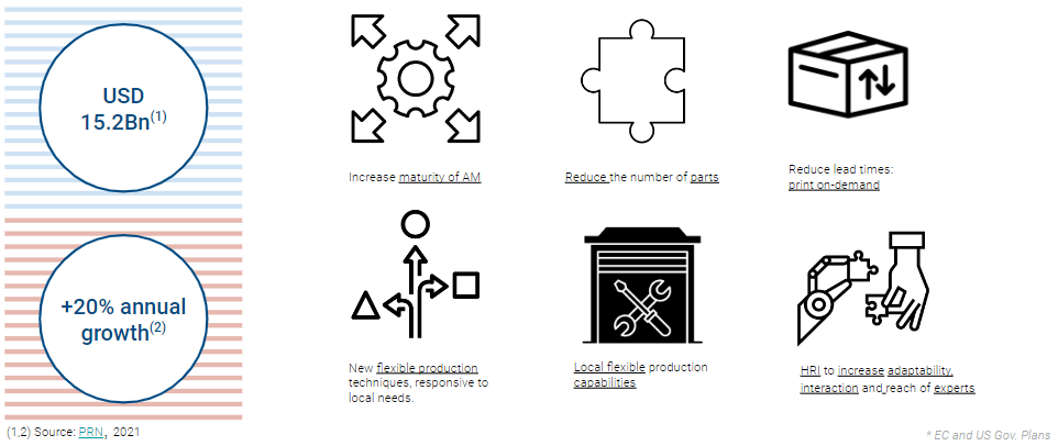
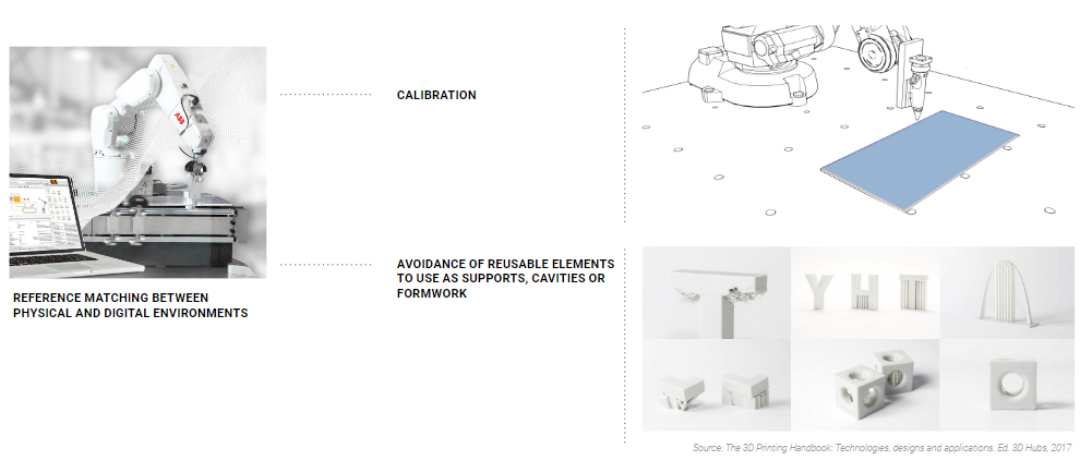
However, there is still an important challenge that it is facing: a gap on matching references between physical and digital environments. This is directly related to everything in contact with the printing, provoking constant printing base calibration and avoiding reusable elements working as supports, cavities or formwork, that generates an increase of material use, time and costs of production. No matter that some producers would re-implement that leftover material on the process, mainly affecting the generic 3-axis 3DP industry.
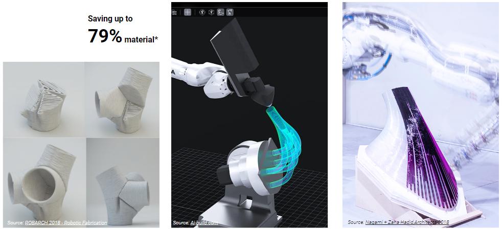
It is true that robotic 3DP offers optimized alternatives that saves up to 79%* material along the process by multiplanar and non-planar slicing geometries or printing over conformal toolpaths.
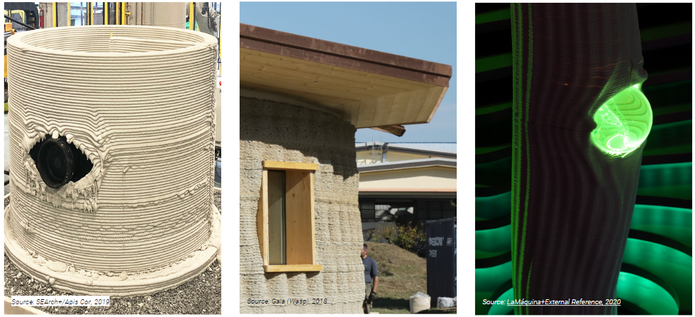
The use of known supports, embedded elements or formwork that can be used multiple times over different prints are normally linked to the design phase and not to the variations that can happen building or fabricating on-site.
Scientific Interest
After reviewing numerous experts from different industries and institutions I kept these 3 statements that guided my research:
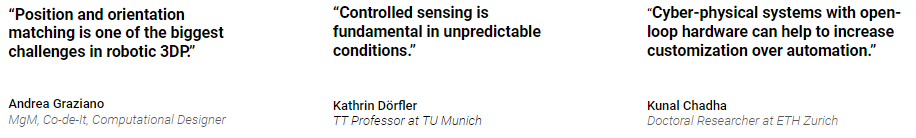
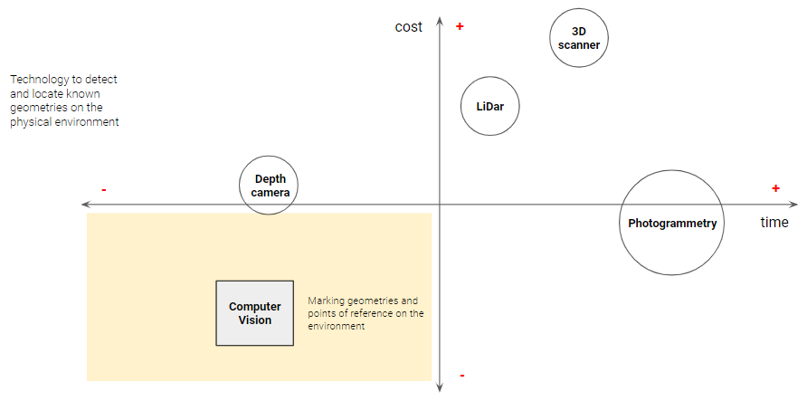
From these conclusions I started a research on the most relevant methodology and technology according to the needs of the project, to detect and locate known geometries on the physical environment, sorting by time and cost of processing.
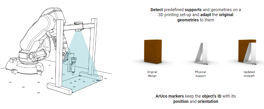
Proposal
An AM fabrication methodology that adapts the printings to supports and embedded external elements by detecting their location through computer vision on a cyber physical set-up.
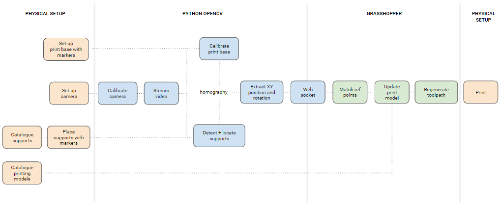
Workflow
Set-up
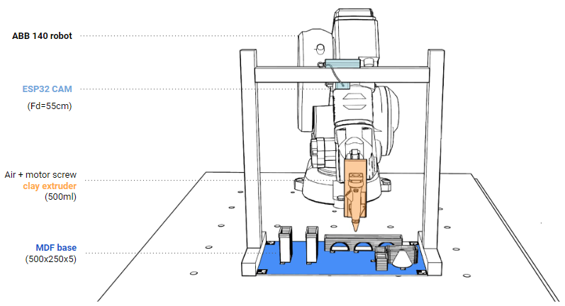
Camera set-up
Camera Web Server
Programming web server through Arduino IDE:
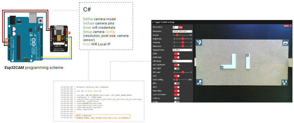
After connecting to a local IP Wifi network, the recorded video can be streamed on a local web server where we can obtain captures, modify image settings and even correct the lense distortion. However this correction is not enough, so a re-calibration of the camera will be needed to match the image 2D pixels on the 3D space reference points.
Camera calibration
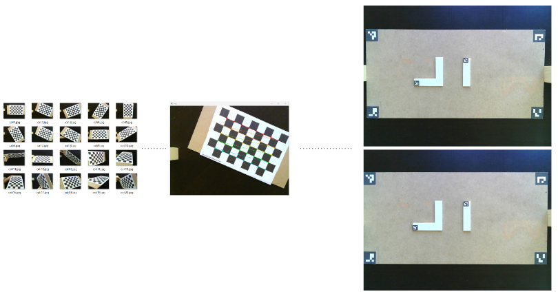
A 0.0432 correction was made in the process.
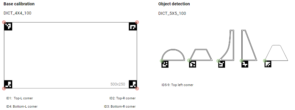
ArUco Markers
- Place ArUco markers on every corner of the print bed (for calibration) and on every known physical support
- Extract XY position and orientation of one corner of each marker
- Send and match those values with a reference point and a plane of the digital model in Grasshopper
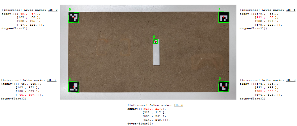
ArUco markers tagging:
ArUco markers detection:
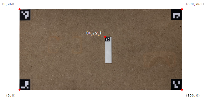
Homography
The process of referencing the elements and place them on the printing bed would be matched through homography, becoming the bottom left corner the (0,0) point matched on the digital model.
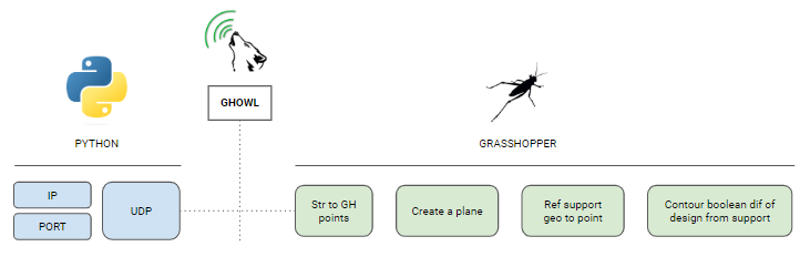
Data implementation
The streamed data array implementation from Python OpenCV to Grasshopper was send through a local websocket UDP, connected with the GH plugin GHowl to update and match the points on the digital model as follows:
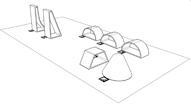
Case Study
To put all the workflow and technology into practice I made a Case Study keeping the set-up and methodology I planned:
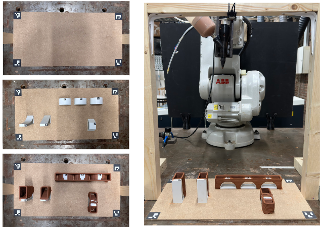
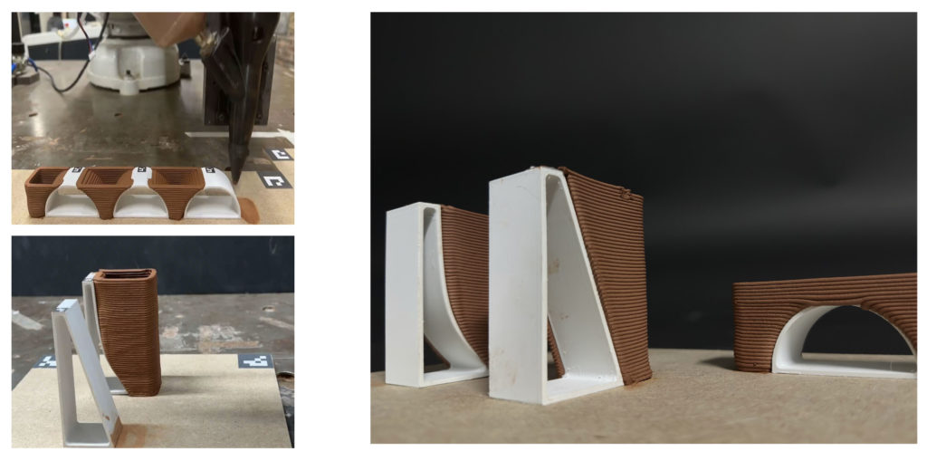
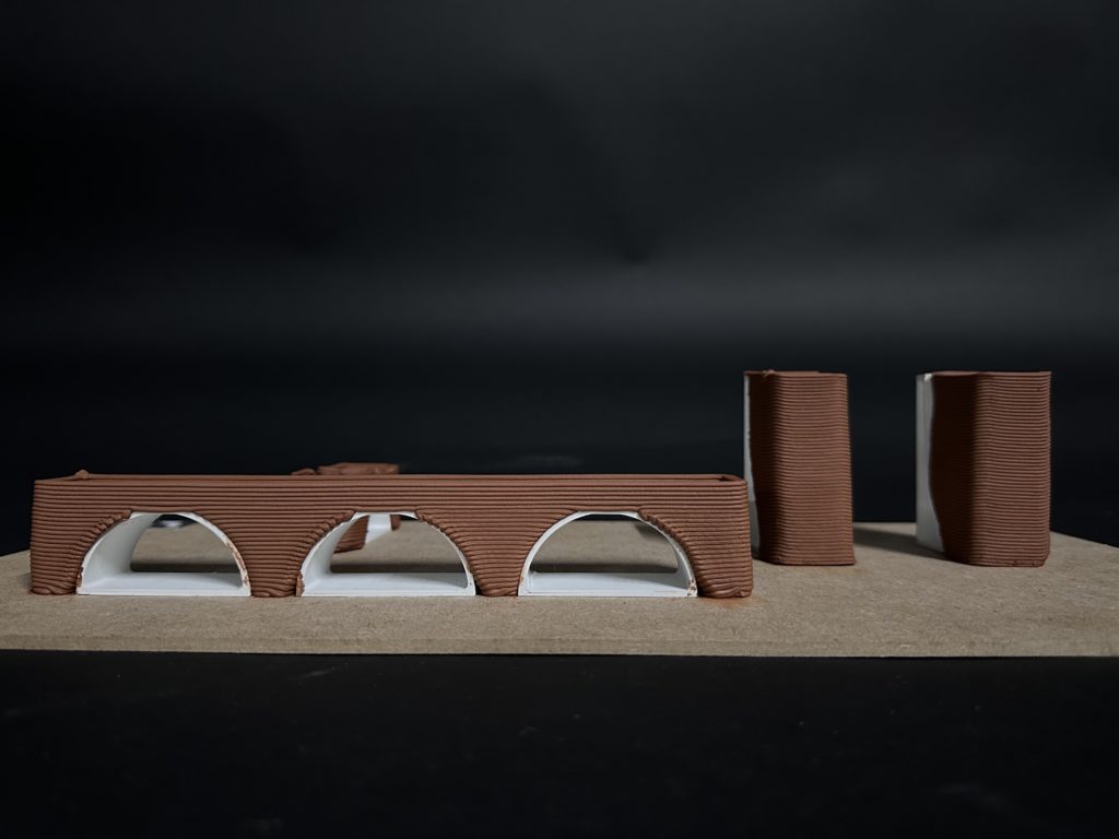
These were some of the results of the printing process:
Further steps
There were 3 alternatives studied as further proposals of the project for next term:
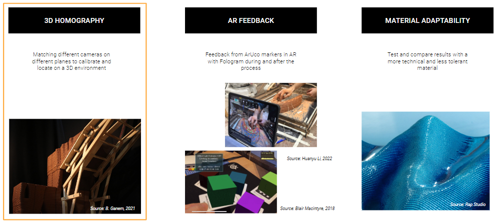
The accuracy of the methodology of detecting arUco markers can be tested by this 3 methods:
- Matching different cameras through homography as well as shifting to a more technical material and layer height with lower tolerance by printing process with plastic.
- Matching a AR digital model through Fologram during and after the printing process, also increasing its interaction.
- Matching the physical print during and after the process with the digital model through AR technology using Fologram and the properties of identifiying and orienting virtual elements to the arUco markers.
