
This technical report details the computational workflow developed for our final structural optimization assignment. The project methodology follows a rigorous sequence: initial form-finding, stress-line analysis, lattice topology selection, and cross-section optimization, culminating in a robotic fabrication strategy.
General Workflow Overview
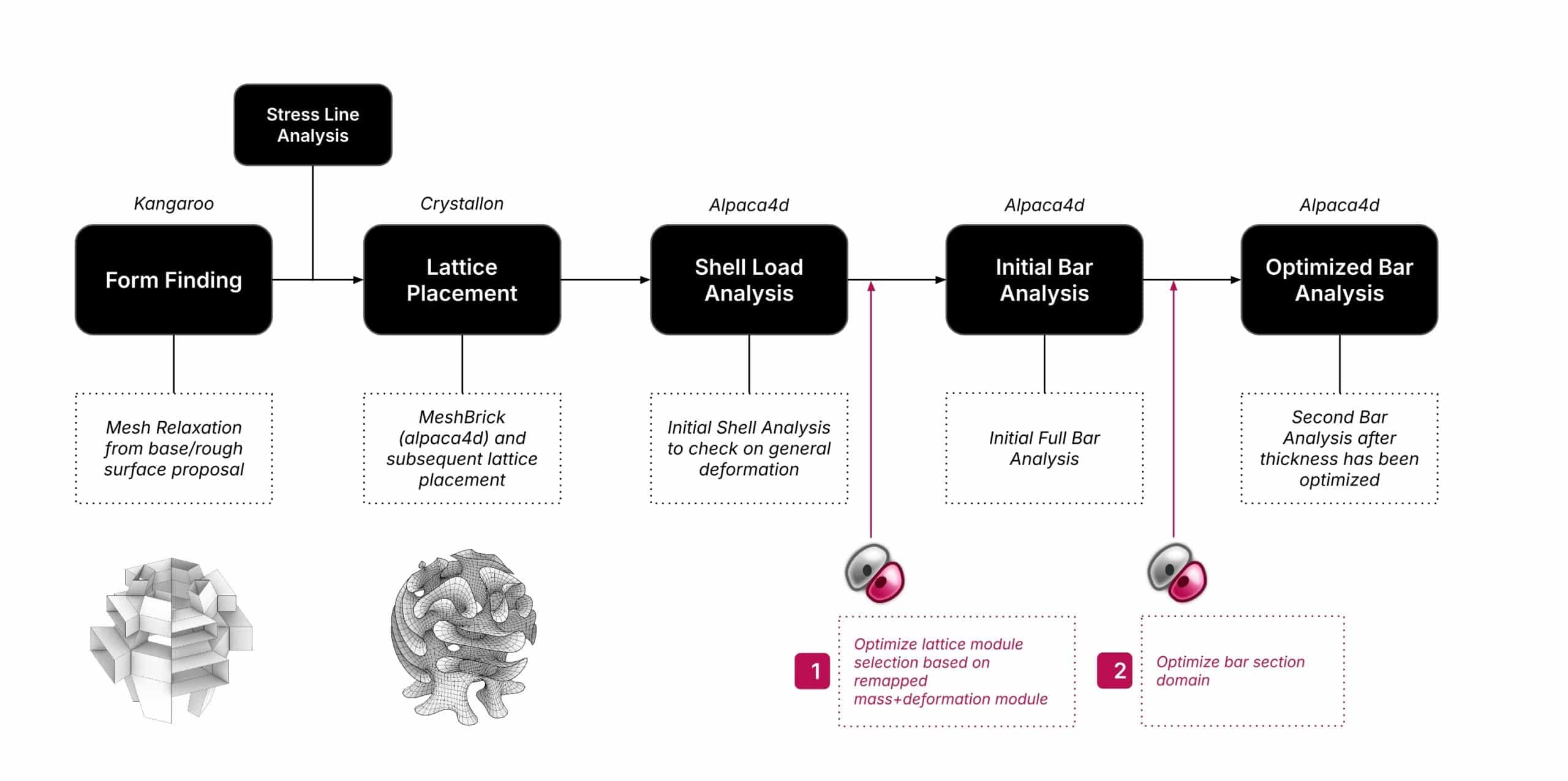
The design process is structured around a linear algorithmic pipeline. It begins with form-finding utilizing Kangaroo physics, followed by a meshing and thickening phase designed to house Crystallon lattice modules. An intermediate step involves analyzing the geometry’s stress lines to inform material distribution. Once the lattice structure is generated, we perform a general shell analysis under gravity and wind loads to identify critical deflection points. These points serve as the fitness objectives for our evolutionary solver, Galapagos, which we utilize twice: first to determine the optimal lattice topology, and second to optimize bar thickness.
Computational Form-Finding
The geometric generation began with a subdivided core mesh relaxed within a pre-defined, confined boundary geometry. To ensure the surface remained feasible for construction, naked mesh edges were constrained using sphere collisions. This specific constraint logic resulted in an organic, non-intersecting folded surface.
Shell Analysis and Stress Evaluation
Before lattice generation, the geometry was evaluated as a continuous shell structure. The thickness of this shell was not uniform; it was computationally driven by two parameters:
1. Z-Height: Vertical positioning.
2. Principal Stress Lines: Generated via Lilypad analysis tools.
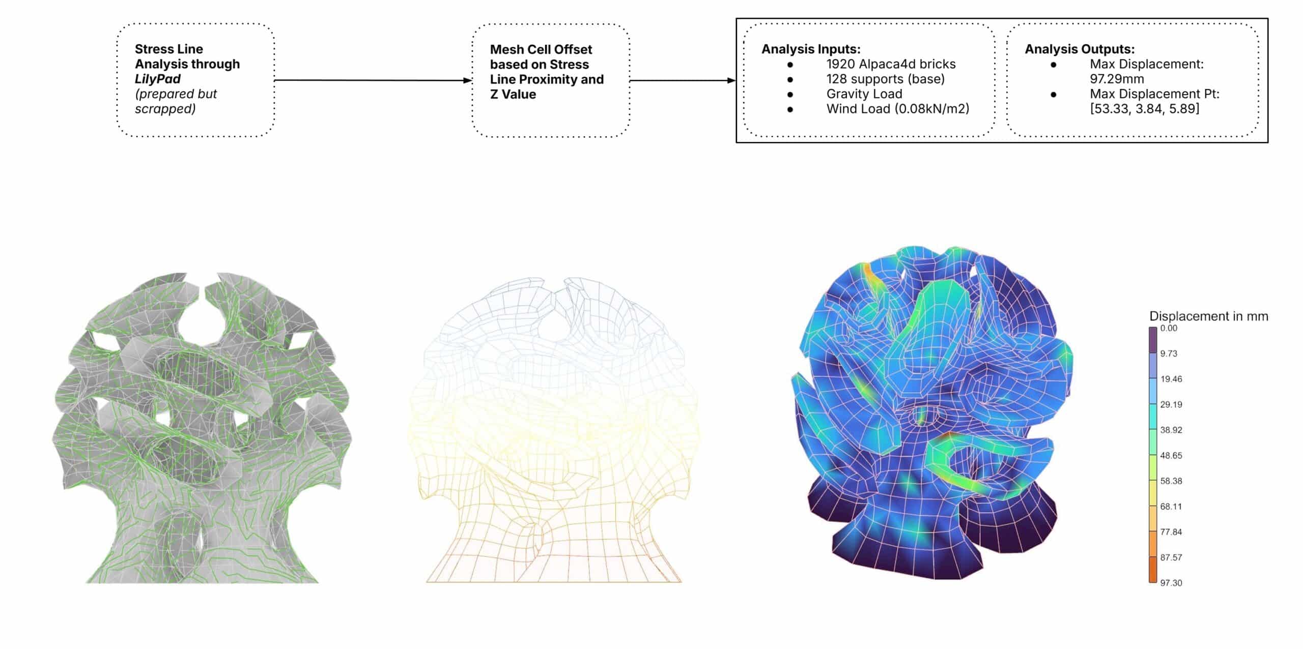
Under the application of standard gravity and wind load vectors, the structural analysis revealed a maximum displacement of 97 mm, located specifically in the upper arms of the cantilever.
Optimization Phase I: Topology Selection (Lattice Module)
To transition from a shell to a lattice, we initiated a full-bar analysis to identify the most efficient unit cell. Due to computational time constraints, we did not run the evolutionary solver on the entire structure initially. Instead, we applied Galapagos specifically to the area of maximum deflection identified in the previous shell analysis.
We manually cycled through the options on the full structure to verify the solver’s findings. The optimal topology was identified as the BC Cubic module. The performance metrics for this initial lattice iteration (assuming a uniform 12.5 mm diameter and 5 mm thickness) were:
• Mass Displacement Factor: 0.094
• Total Mass: ~1,500 kg
• Maximum Displacement: 72 mm.
Optimization Phase II: Cross-Section Sizing
With the optimal crystal cell selected, we proceeded to optimize the bar diameters. Rather than utilizing a static thickness value throughout the structure, we defined a variable section domain. The structural logic dictated that members should become thinner as their Z-value increases.
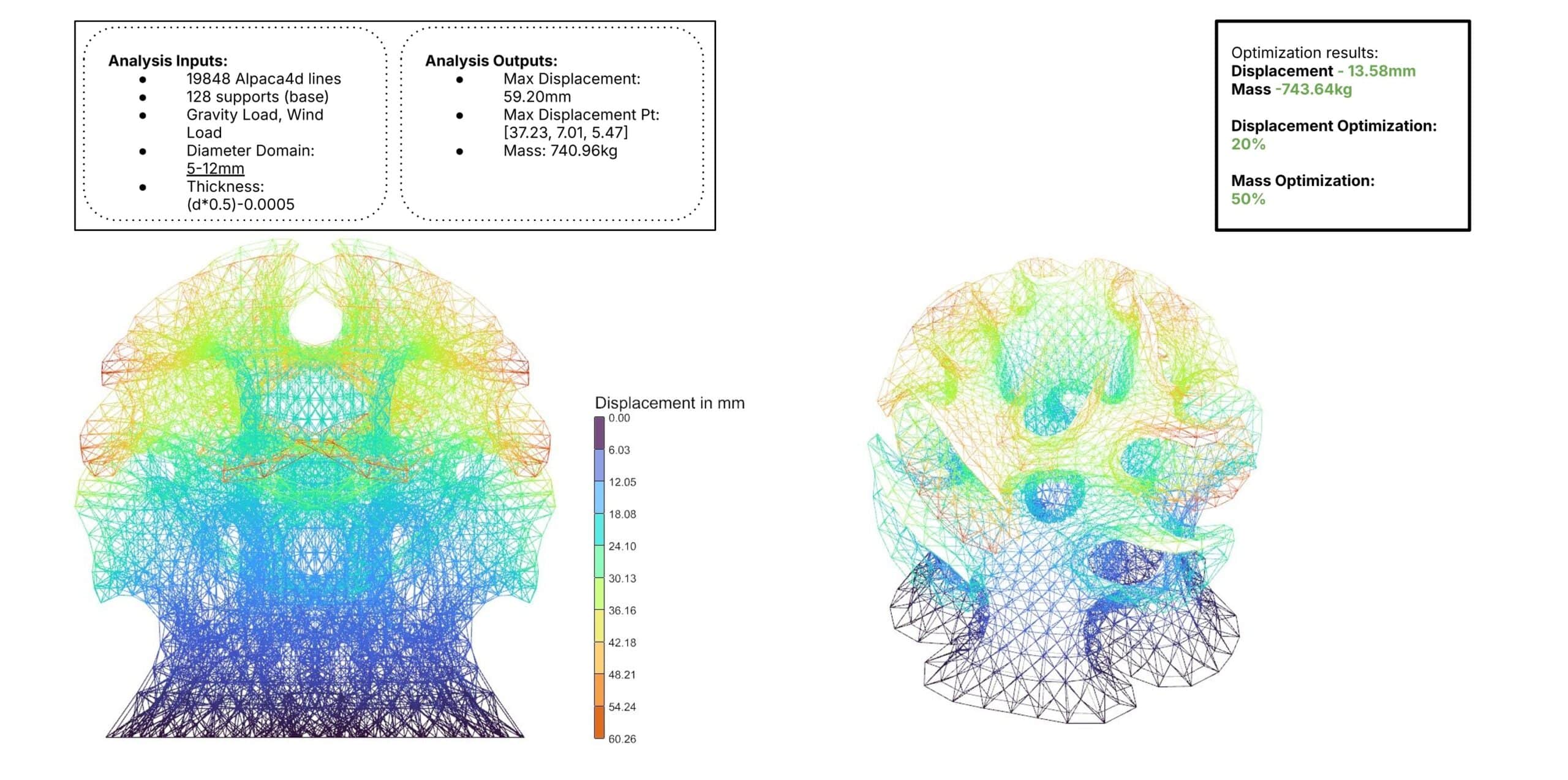
Similar to the previous phase, we utilized Galapagos on the high-deflection areas and manually cross-checked domain ranges. The best-performing domain was identified as 5 mm to 12 mm. It is important to note that in this workflow, the thickness is derived from a formula dependent on the diameter.
Final Structural Results
The implementation of variable cross-sections yielded significant efficiency gains. The final structure exhibited:
• Maximum Displacement: 59 mm (a 20% optimization in deflection compared to the uniform lattice).
• Total Mass: 740 kg (an almost 50% optimization in mass compared to the previous iteration).
Fabrication and Assembly Strategy
Following this three-step optimization, the geometry was converted into a lattice and segmented into core components derived from the base mesh seams. These parts were further subdivided to accommodate the build volume of the 3D printers, then oriented and prepped for manufacturing.
• Printing: The fabrication utilizes a robotic pellet extruder with PET Glass Fiber pellets. This hardware choice allows for precise control over tool paths, extrusion rates, and velocity.
• Assembly: The printed components are joined using a combination of chemical bonding, heat clamping, and mechanical joinery.
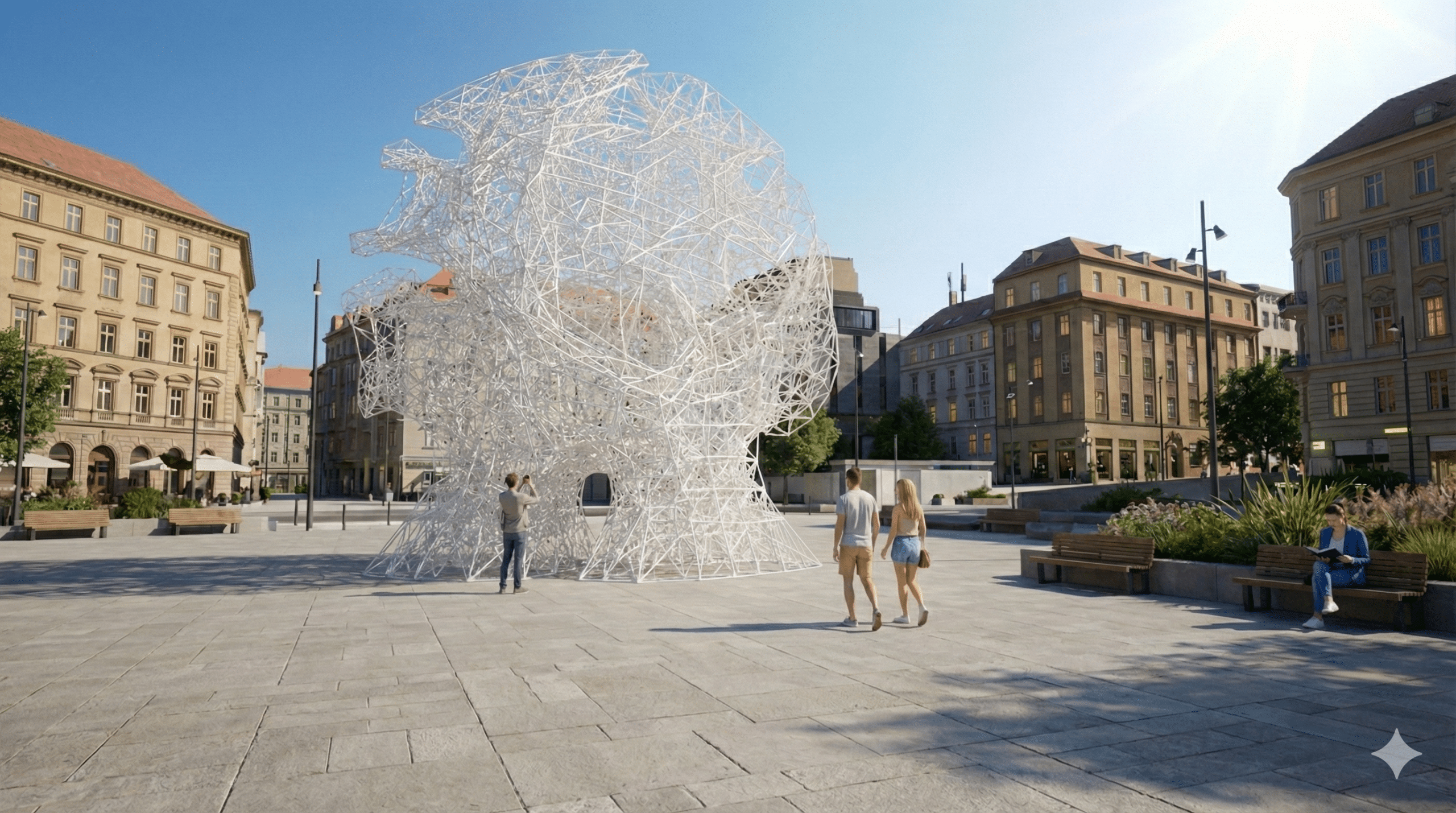
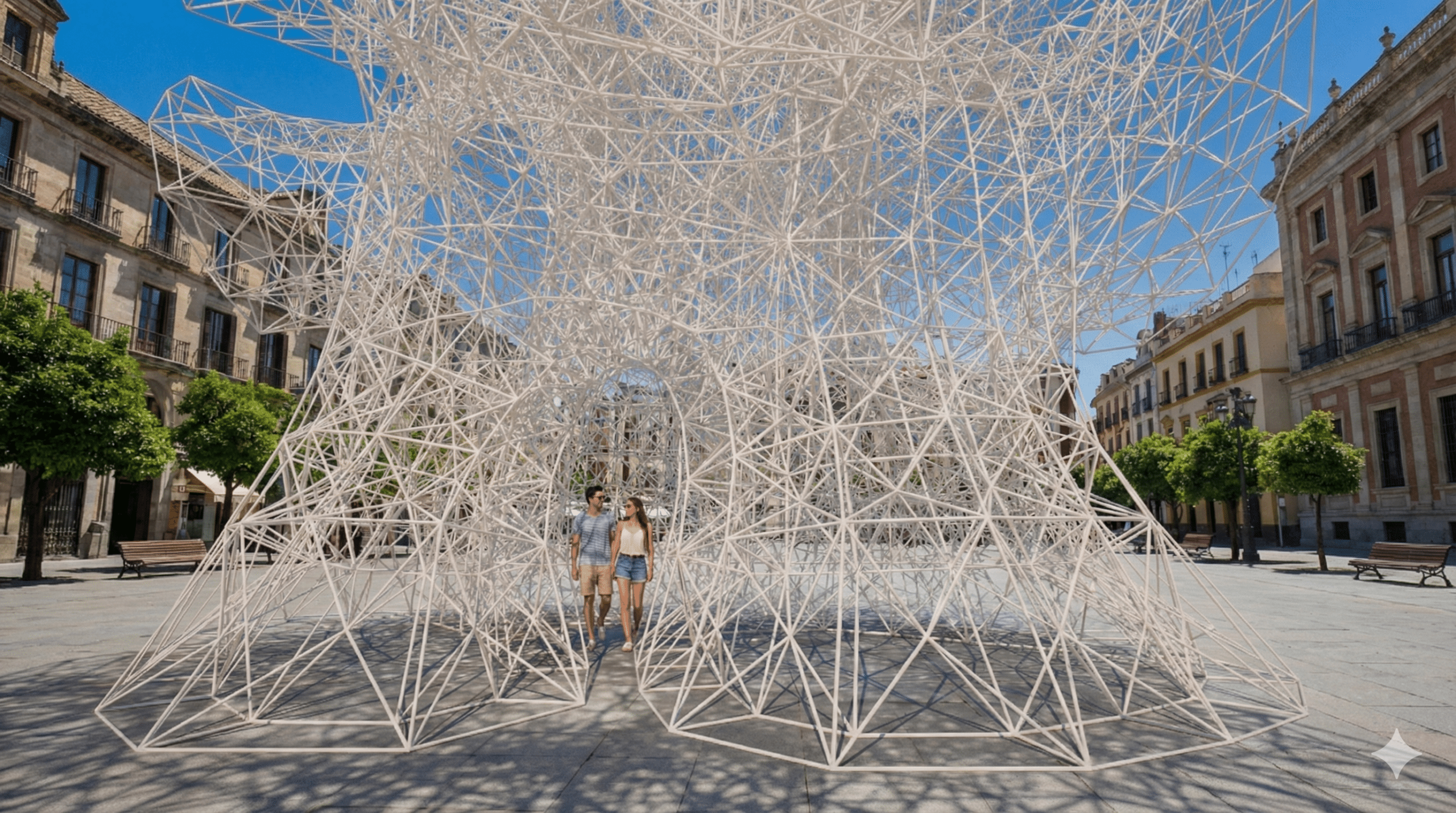

Note: The project visualizations were rendered using Twin Motion and enhanced with Nano Banana to investigate the spatial and atmospheric qualities of the design.
