
Exploring Clay 3D Printing Through Viscosity, Speed, and Time
For the Shape exercise within Anatomy of the Machine, we worked with clay as a material, specifically focusing on robotic 3D printing using clay extrusion. The objective was to understand how material behavior, robotic parameters, and geometry interact, and how form emerges from the machine–material relationship.
Material Calibration: Clay Viscosity
We began with manual robotic tests to calibrate the viscosity of the clay and understand its behavior during extrusion.
The first mixture consisted of 2 kg of clay with 15 mm of water. This formula resulted in a very dry material; however, it was useful for initial manual handling tests with the robot. At this stage, we focused on basic movement, extrusion control, and waiting time between actions. It was during these early tests that the first notion of the “blob” emerged as a recognizable unit of form.
We then tested a second mixture with 1.5 kg of clay and 50 mm of water, achieving a higher viscosity and significantly better extrusion behavior. This mixture allowed us to increase printing speed and obtain more consistent results.
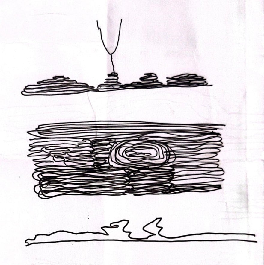
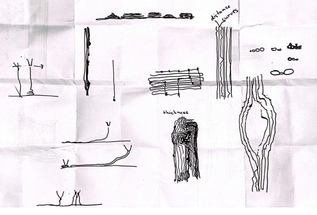
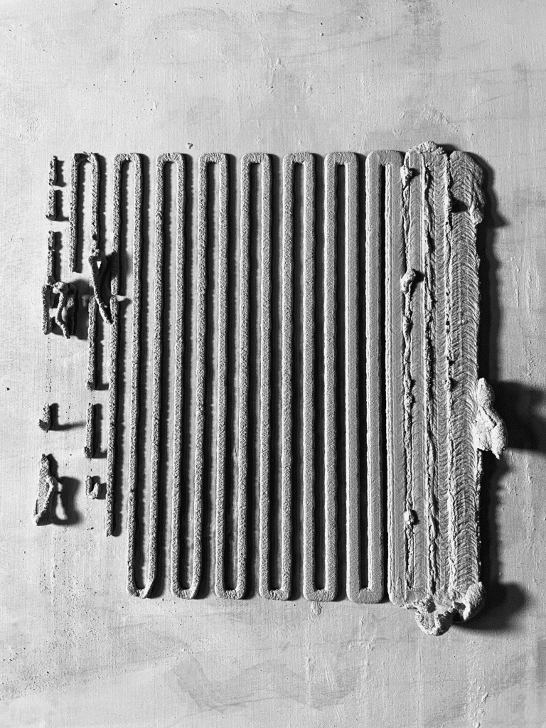
Anatomy of a Line: Speed vs. Height
Using the second clay mixture, we conducted a series of tests based on simple linear paths programmed in Grasshopper. These tests explored the relationship between printing height and speed, forming what we referred to as the Anatomy of a Line.
Through this process, we identified a maximum effective printing speed of 15 mm/sec, beyond which material continuity and form stability were compromised.
1st Iteration
Line Spacing: 15 mm
Speed: 3 – 30 seg

2nd Iteration
Height: 1 – 25 seg
Line Spacing: 10 mm
3rd Iteration
Height: 2 – 10 mm
Speed: 1 – 25 seg
Spacing: 10 mm

Preliminary Results: Lines progressively shift from thick to thin as speed increases. At higher speeds, the clay tends to detach from the surface.
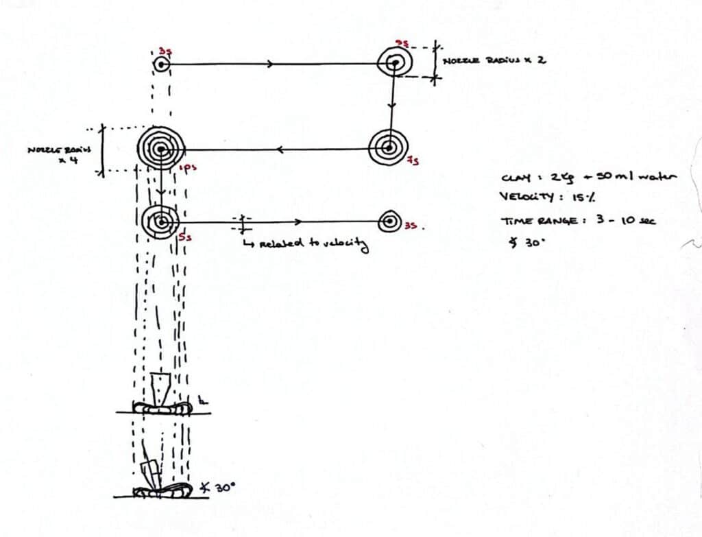
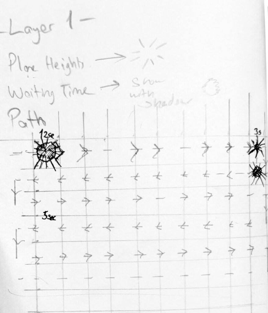
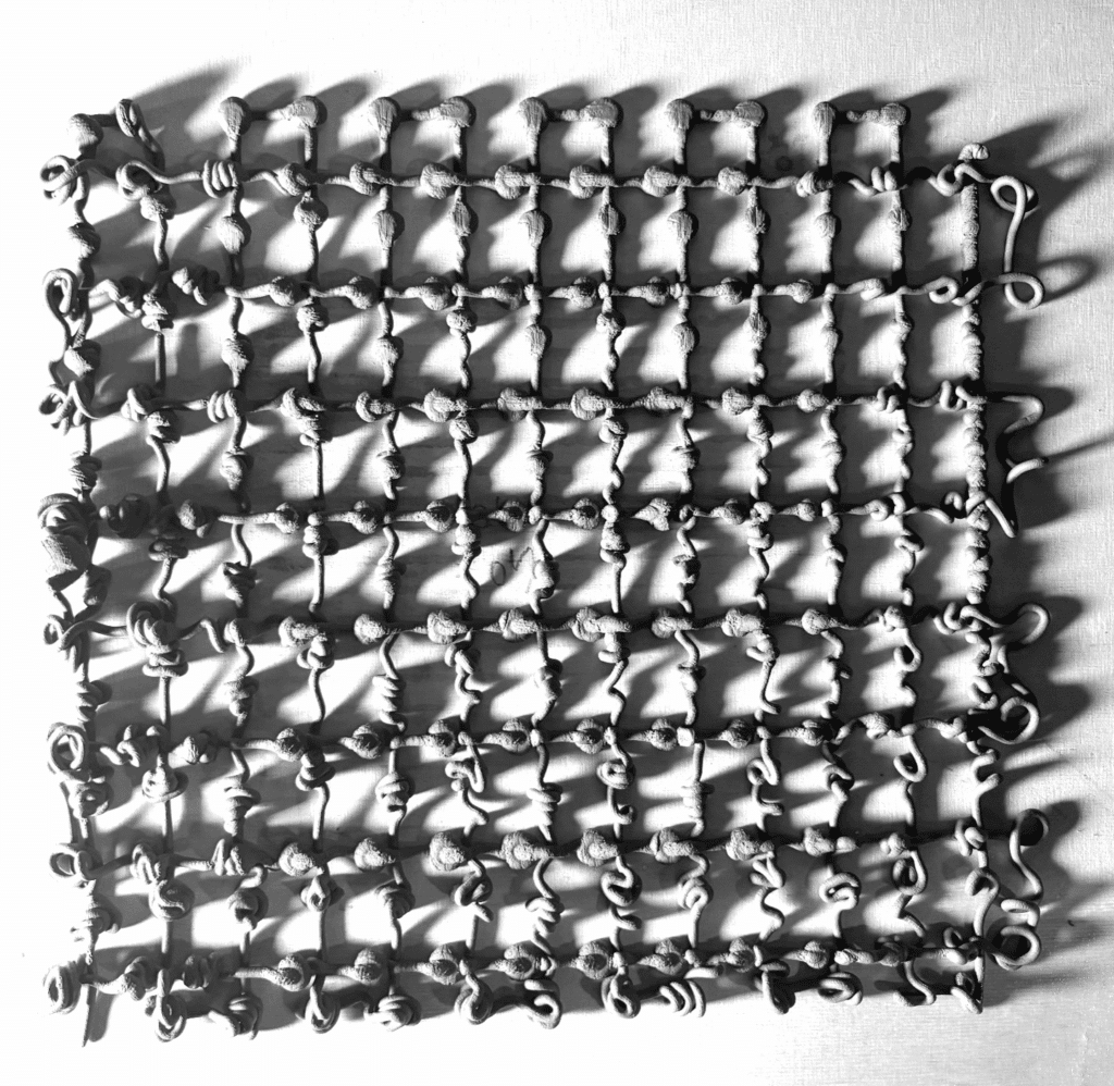
Anatomy of a Blob: Height and Waiting Time
In parallel, we developed a second set of experiments called Anatomy of a Blob. In this case, we focused on two main parameters:
- Printing height
- Waiting time at each plane
The blobs were arranged in two layers forming an orthogonal grid, allowing us to read variations systematically. Beyond generating gradients based on height and waiting time, the blob patterns also visually recorded the directionality of the robotic arm, embedding the machine’s movement logic into the geometry itself.
Iterative Exploration
Through this setup, we explored the operational ranges of the system and produced three main iterations:
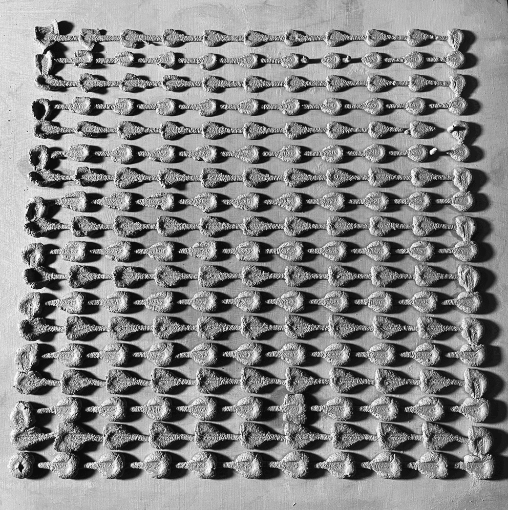
Iteration 01
- Height: 1–5 mm
- Waiting time: 3–10 mm/sec
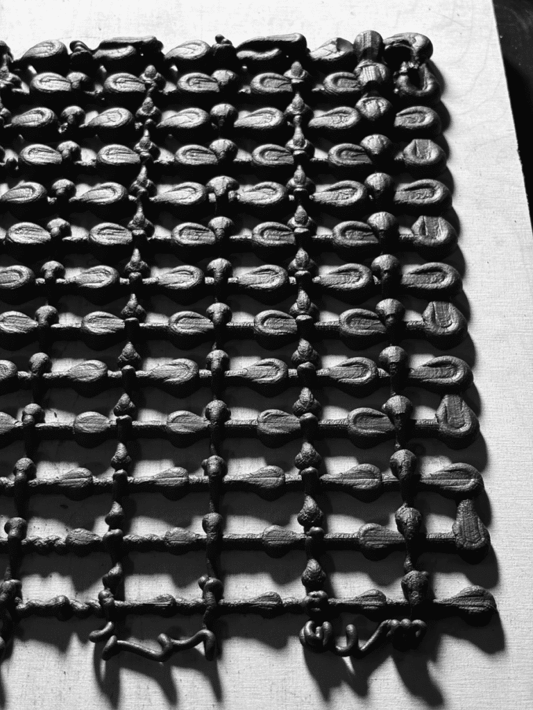
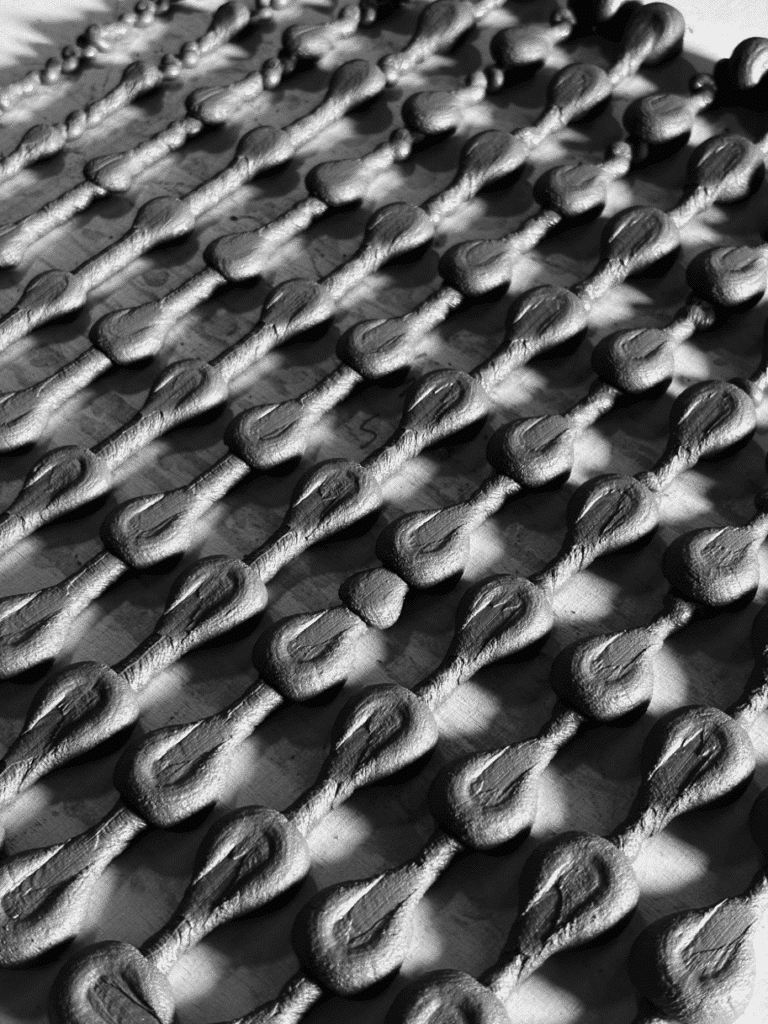
Result: Clear blob formations with smooth gradients across each plane.
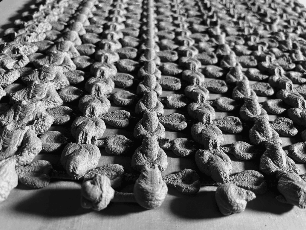
Iteration 02
- Height: up to 14 mm
- Waiting time: 1–10 mm/sec
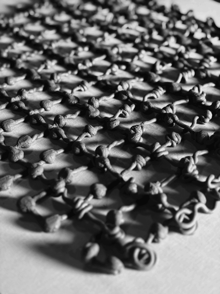
Result: At greater heights, blobs transitioned into fine lines and spiral formations, indicating material collapse and flow dominance over accumulation.
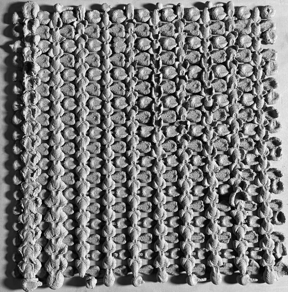
Iteration 03
- Height: 1–8 mm
- Waiting time: 1–20 mm/sec
Result: A hybrid gradient combining spirals, blobs, and both thin and thick lines, revealing a broader expressive range of the material–machine system.

Conclusions
This exercise demonstrated how shape is not predefined but rather emerges from the interaction between material properties, robotic behavior, and temporal parameters. By systematically varying viscosity, speed, height, and waiting time, we were able to read the anatomy of the machine through the forms it produced, with the blob acting as a fundamental unit of material expression.
