
Aggregation-oriented, Extinction Museum, Pozzuoli, Naples, Italy.
Concept
The extensive environmental deterioration and the extinction of countless animal species have been attributed to the Anthropocene period, a geological epoch that represents the tremendous impact that human activity has had on the Earth’s ecosystems and climate. Anna Tsing, Heather Swanson, Elaine Gan, and Nils Bubandt explore the numerous ways that human conduct has affected animal extinction during the Anthropocene epoch in their book “Arts of Living on a Damaged Planet.”
The initial thought was to create a labyrinthine design that can also be more participatory and immersive. The inquired project was to structure a museum that allows visitors to pick their own route through it, choosing which exhibits to view and in what sequence. Visitors may now customize their visit to suit their own interests and tastes, making it more memorable and personal.
Site Analysis
The site is located in the middle of a crater filled with plantation and few open surface areas that the structure can utilize. Thus, commencing with the site analysis the main idea was to protect each individual tree and plant while to demonstrate the main free surface areas in order to create atrium spaces to accommodate museums program. This approach aims to be part of a general strategy in terms of environmental-oriented thought.

With this in mind agents with flocking, stigmergic and wandering movement were utilized to engulf the land plot and show the dominant flows. On each individual tree a point of repulsion was created while on each free surface an attraction point was set.
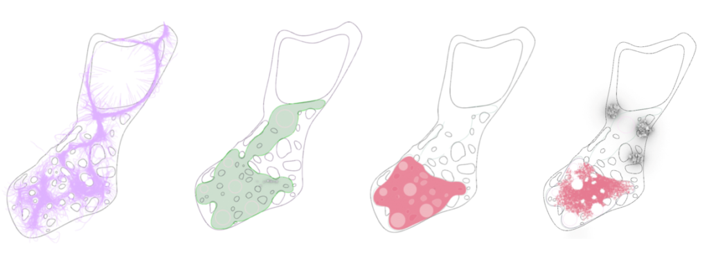
The aforementioned figures, which were created using mesh and surface geometries and plotted in Rhino, show the author’s method for developing the global constraints for this aggregate. The findings showed that powerful flows dominate a sizable portion of the site, forming the scenery and setting the boundaries for the assembly that will serve as the primary museum building while avoiding the plantation and generating atriums for use as program amenities.
Aggregation Parts
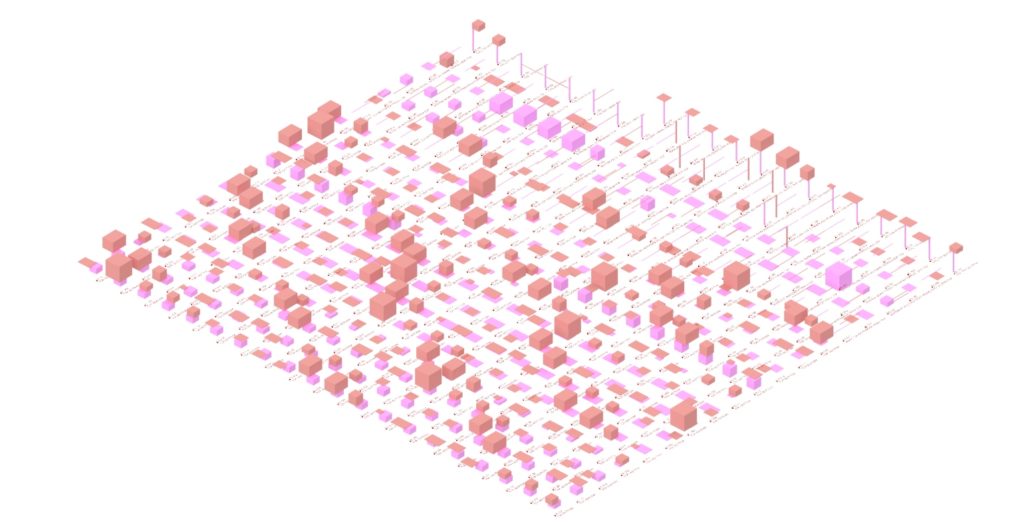
Starting pieces for the Houdini and Grasshopper software were built using a variety of computational plugins and VEX programming with the goal of striking the right balance between structural and architectural elements to go forward with the aggregation initial guidelines. The components are shown below and include smart facade elements, smart room separators that double as plantation mounts, stairs, ramps, wood plates, timber columns, and timber beams. Smart refers to whether or not each element’s hierarchical order emerges based on the joinery. The components may be adapted to any situation and altered while being horizontally rotated.

Control and the effective creation of an amalgam that makes sense architecturally are the two key concepts in aggregation. The flowchart below shows the five levels of control that were developed as a result. The module connection is initially examined while supports are being created on the appropriate places for each piece. To appropriately manage the distribution of modules, a generic catalog with minimum and maximum components for each category is then generated. The forced adjacencies that force elements to zone out or attempt to link by force with the appropriate neighbors are the most significant filter, but the site’s overall constraints ultimately have the greatest sway. Additionally, all of the joints’ applied grammar is shown through potential connections.

The aforementioned situation, where the necessary outcome is for the facade elements and the room dividers to appear when there is a free surface on the outside to generate a covering membrane and a space division within, is validated using a smart module aggregation.

It can be seen that actually the parts are covered in their corresponding facade elements while in the middle of the structure there are no smart elements that overlap with the room dividers appearing properly. The structural base is looking correct since the columns and the beams create a base for the whole process to be initiated and have a proper facing lower end.
Aggregation Variations
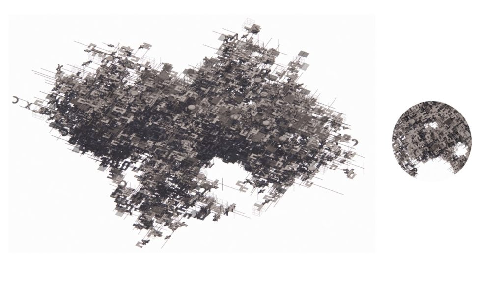
Initially the aggregation process needs to illustrate a satisfactory result without overlapping and hovering elements for this reason three variations were performed, the support oriented, the mesh constrained and the combination of both with 10000 elements each.
Support-oriented Structure
It can be seen that support based aggregation creates a multilevel structure that cannot be contained for the site prerequisites while some elements are placed in a wrong direction, parameters that will be corrected in the next cycle of simulation.
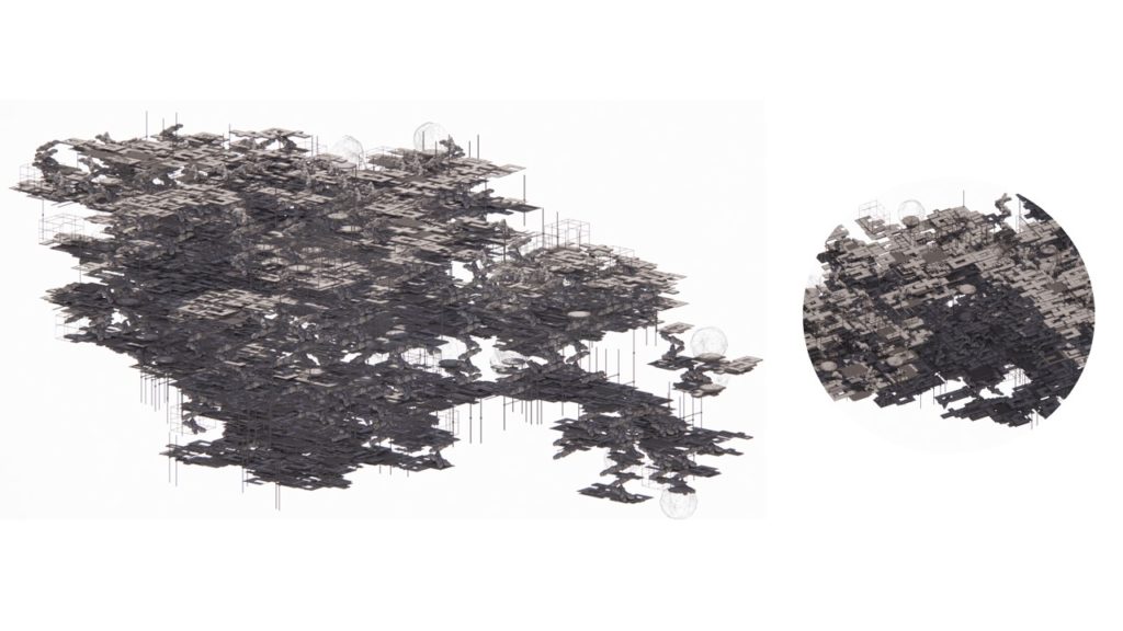
Mesh-Constrained Structure
The second aggregation appears to be more around the site’s prerequisites but the main disadvantage here is that there are a lot of structural free roaming elements meaning there must be a reformation on the limitation criteria in the aggregation control layers.
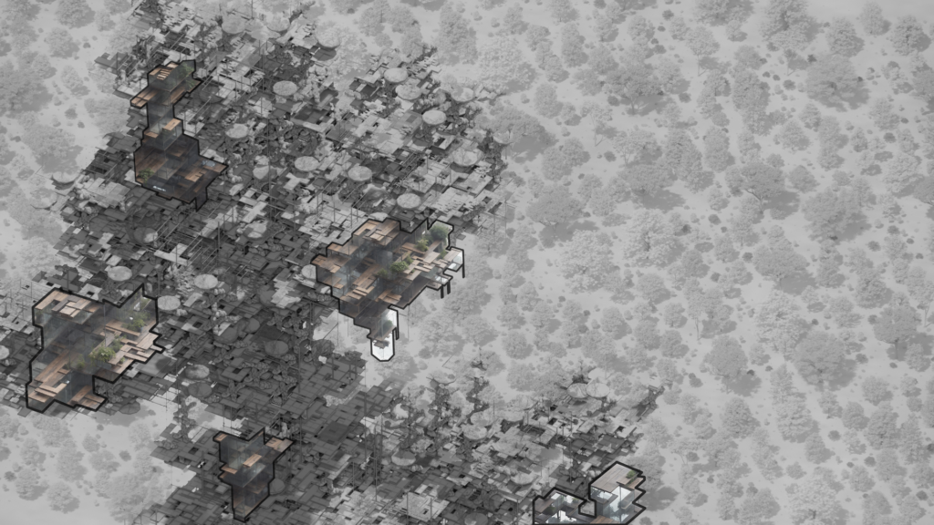
Final Structure
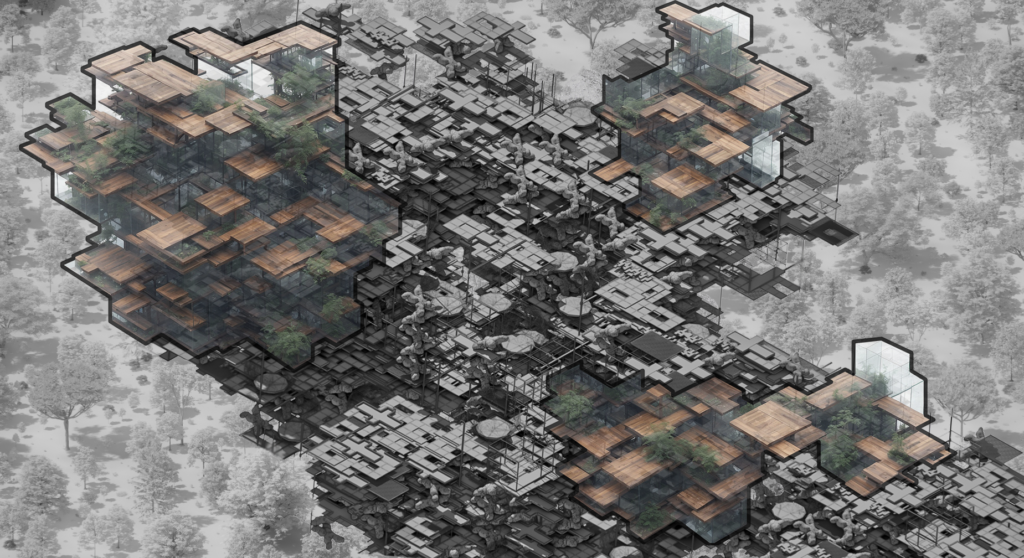
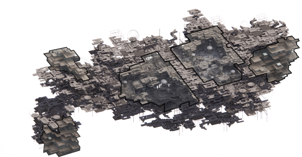
To sum up. Following the above-mentioned control layer reforms, the suitable structure is selected using both of the aforementioned approaches since the vertical structural components are positioned correctly, there are no elements that are incorrectly rotated, and the free surfaces are acceptable. While there are several observation spots without inverted parts and floating staircases, the remainder of the buildings generate uniformal forms around the site constraints despite the fact that some structural columns need to be transformed in the y-axis in order to contact it. When the structure is installed on the site, analytical views will be displayed at the conclusion of the analysis using cropping planes.
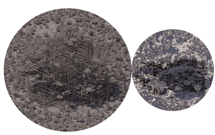
Facade Enclosure
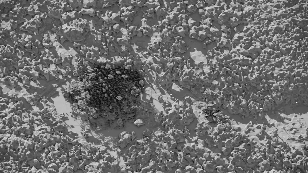
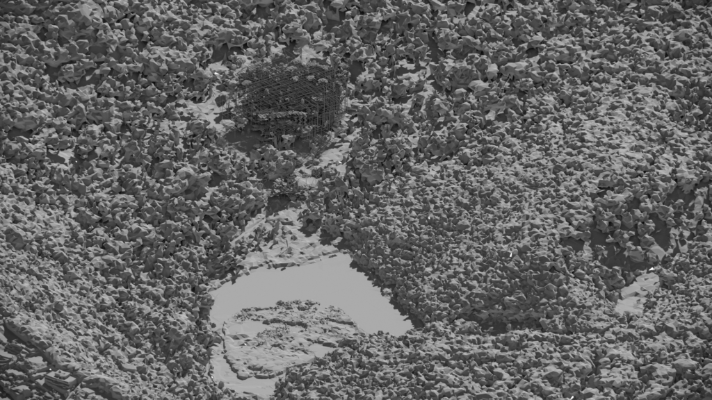
When building a structure, it’s crucial to keep it contained, especially in aggregation logics where the pieces are stochastically assembled and processed, leaving a great deal of uncovered open space. To do this, the author employed a volumetric enclosure of the built building and inflated it to give it a more rounded appearance. This helped the agents with longer paths construct an additional layer of cover above that could be used as a façade.

The above diagrams are exported directly from Rhino and are a product of a sequence of plugin tools to finalize in discrete polyline tubes baking geometries. The shown geometry is the side-structure that accompanies the main museum area while the mesh crawling trails can be distinguished. The size of the main area is enormous and thus only the final products will be illustrated further in the timeline.

Since the findings with 500 iterations are mostly uncovered and the ones with 2000 iterations are overcrowded, it is clear that the simulation time is important in this particular topic. Consequently, 1500 is the selected enumeration for the museum area. Three facades were made, the first of which featured erratic polyline trails, the second of which featured panelized polyhedron shapes, and the third of which featured a more logically oriented shape with polyline tubes that could be easily installed with any kind of photovoltaic panel because their geometry was not organic.
Views
The author aimed to create an agnostic labyrinthian exhibition space to promote a beyond individualism concept. A thinking that is actively related to the anthropocene era, the geological epoch that is being experienced today while in respect to the extinct species, to have a monumental cenotaphic aspect aesthetic.
The computational tools utilized in the process are: Rhino, Houdini, VEX, Grasshopper, Wasp, Pufferfish, Mesh+, Culebra, Weaverbird, Chimpanzee, PlanBee.
