DESIgn for REassembly
“Design for Dis- and Re-assembly; From a column at the Mobile World Congress in Barcelona to inhabitable space Valldaura, to…?”
Our aim for the course is to design 4 columns for the World Mobile Congress, which then will be reassembled and transformed into roofs, walls, and foundations for a small construction in Valldaura. With minimum additional materials, we will design and build a reconstruction, aiming to showcase structural opportunities as well as integrated connection systems developed through digital fabrication and systems thinking.
Dry Connections
We began by drawing, building and testing dry connections.
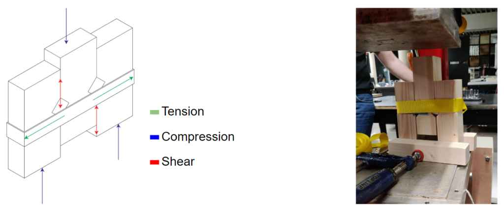
We bundled our timber elements and held them in place with shear connections.
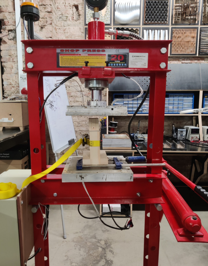
We used the Hydraulic Press in the workshop to create and test shear connections.
We created and built four different strategies for shear connections:
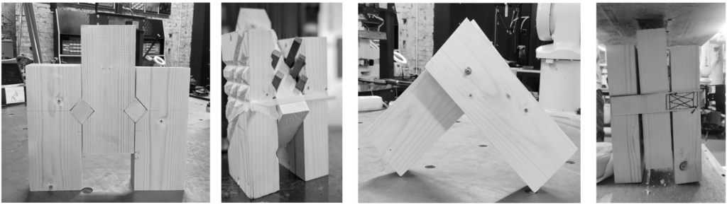
Shear Key Multiple Shear Keys Ball-bearings (hidden connection) Gravel (textural hidden connection)
Components
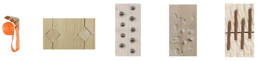
Ratchet Straps Shear keys Ball Bearings Gravel Shear key (timber dowel)
Test 1: Key Connection

TEST RESULT:
4 PUMPS – THE MIDDLE ELEMENT BEGINS TO SLIDE DOWN SLIGHTLY
7 PUMPS – SOUNDS BEGIN SLIGHTLY
8 PUMPS – CRACKLING SOUNDS BECOME LOUDER
10 PUMPS – VISIBLE DEFORMATION OF TIGHTENING BY RATCHET STRAP
13 PUMPS – VISIBLE DEFORMATION OF SHEAR KEY
14 PUMPS- THE MIDDLE ELEMENT BEGINS TO COME DOWN WITH EVERY PUMP
18 PUMPS – THE MIDDLE PIECE IS AT THE SAME LEVEL OF THE TIGHTENING BOX
PROS:
- Very easy to assemble with hydraulic press.
- Very strong connection.
CONS:
- Difficult to reassemble.
- Requires a hydraulic press.
- Time consuming.
- Choke point in assembly.
Test 2: Shear connection with gravel
CONSTRUCTION:
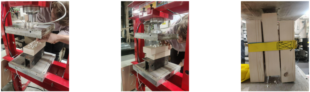
COMPRESSED GRAVEL FIRST ON ONE SIDE THEN ON THE OTHER SIDE RATCHET STRAP TO HOLD THE PIECES TOGETHER
TEST
UP TO 5 TONS OF PRESSURE
22 PUMPS UNTIL 10MM DEFORMATION
26 PUMPS UNTIL 15MM DEFORMATION

PROS:
- Very easy to assemble with hydraulic press.
- Very strong connection.
CONS:
- Difficult to reassemble.
- Requires a hydraulic press.
- Time consuming.
- Choke point in assembly.
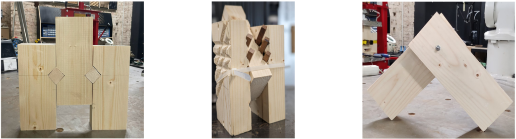
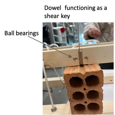
Test 3- Shear connection with ball bearings
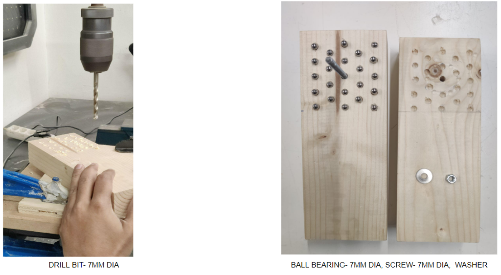
PROS
- Very easy to construct with CNC.
- Easy to change the angle of connection.
- Hidden connection.
- Creates a connection with bricks.
CONS
- Very vulnerable to human error if constructed by hand.
- Can be done without manual labour. (CNC)
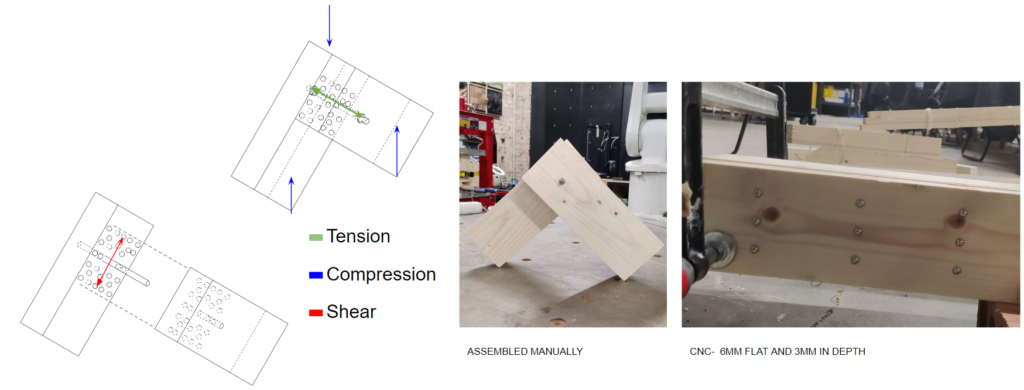
Experiment – 4 Multiple shear key connection
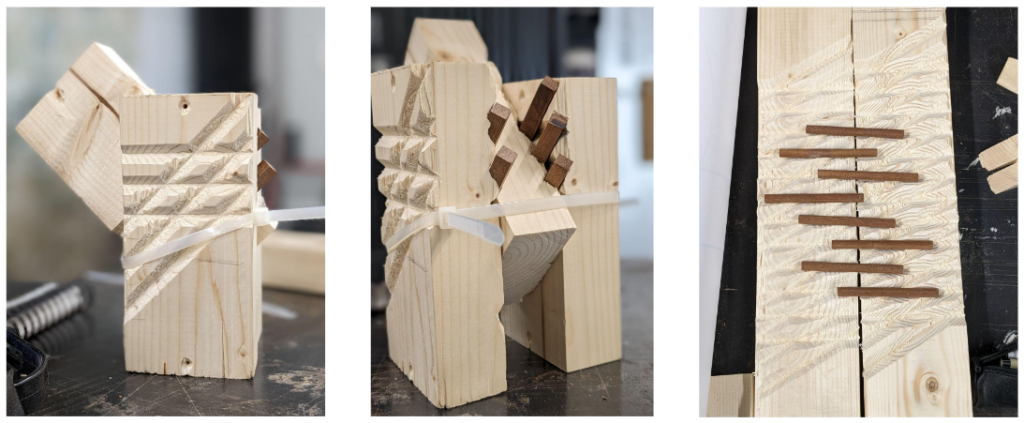
PROS
- Very easy to construct with CNC.
- Adds one variation of connection angle.
- Can be done without manual labour. (CNC)
CONS
- Connects are visible.
- Less options of angles than ball bearing.
Conclusion
The combination of ball bearing and multiple key connection were our options of choice
- Quickness in construction
- CNC precision
- Flexibility of angle and material connection
- Aesthetic integrity
- Strong enough to sustain shear forces when implemented in the column
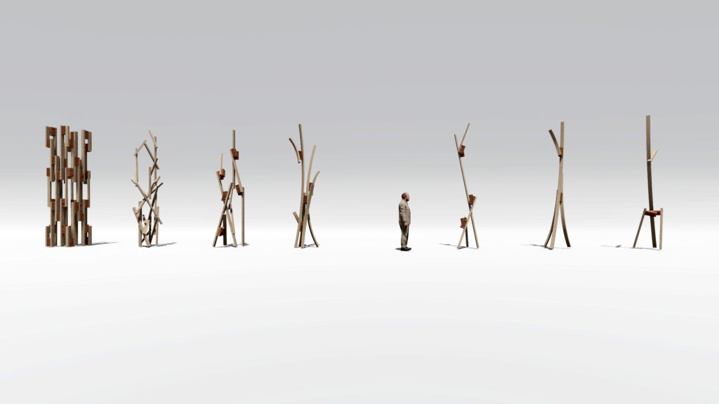
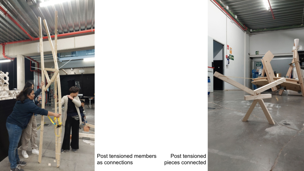
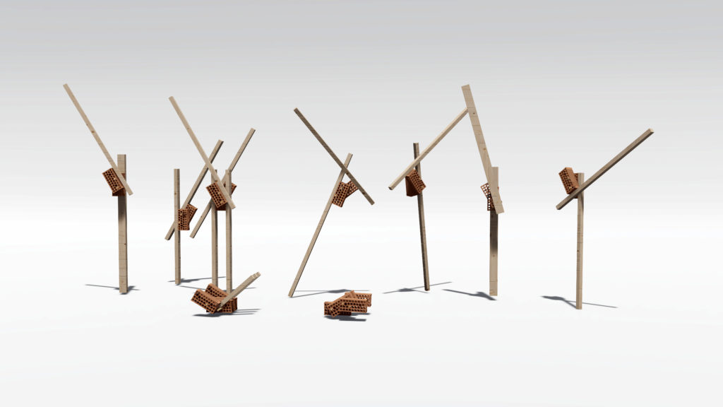
Post-Tensioning
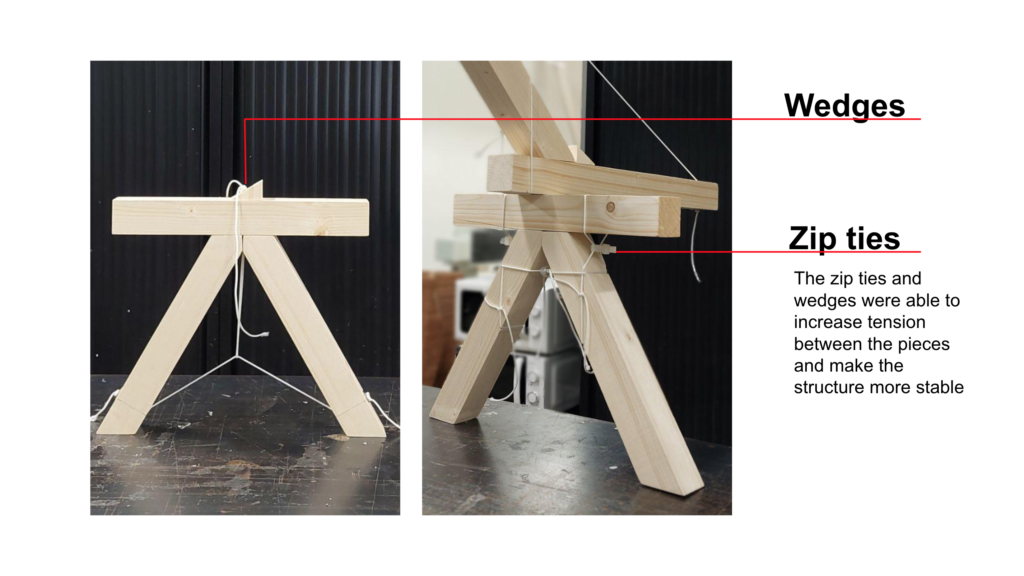
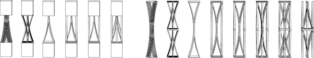
We experimented the post-tensioning of wooden sticks through the construction of “letters”, as a way of testing both different angles and aesthetics.
The potentials of this study is to show how post tensioning can be used in smaller systems that can be parts of a bigger structure, in order to facilitate assembly and disassembly. Normally what it is perceived in structures is post tensioning only being functional in the conclusion of construction, which makes it more difficult for structure stability during the construction process and also assembly and disassembly of the parts. Using this strategy the pieces created can be used as joints within other members, or as members of a structure that can be joined with different joint systems. This increases flexibility of the designs.

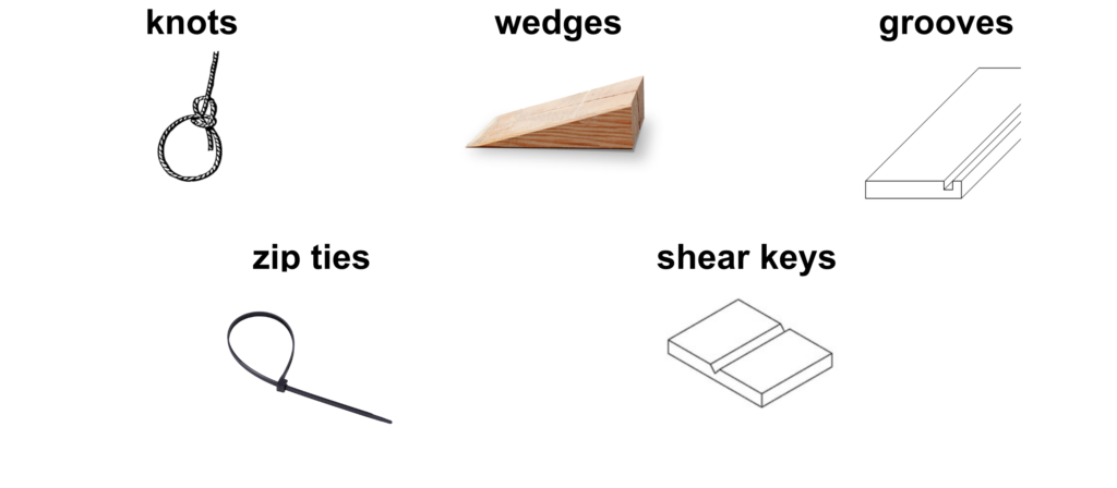
Locking Methods

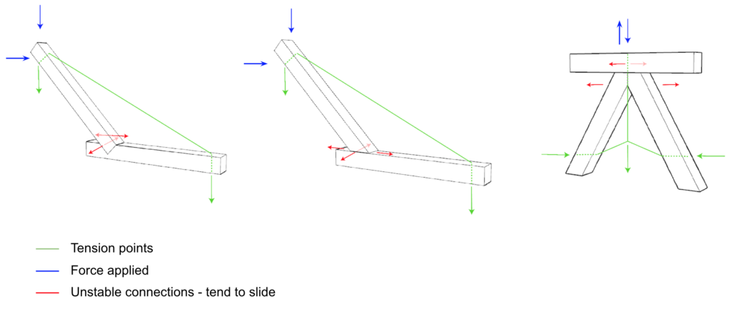
Unstable Letter Types
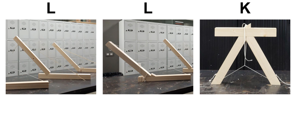

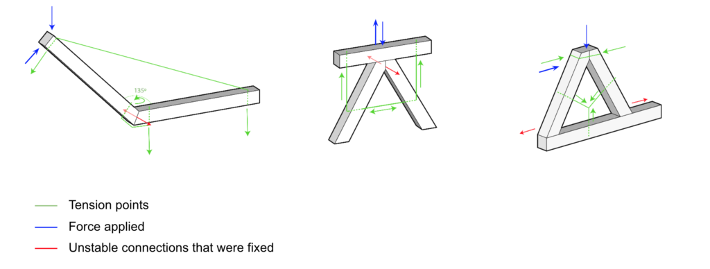
Stable Letter Types


Conclusion
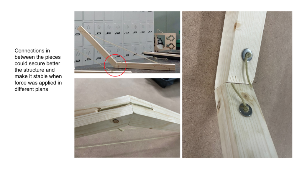
_Wedges and zip ties can intensify the tension of the knots and properly lock the system
_Only when force was applied to one plane the systems were perfectly stable, but in different planes normally they had issues
_The pieces needed to be in a closed loop (tension from the outside or inside)
_Ideally it should have more locking systems such as shear key/embos to prevent sliding
_Triangulation of the forces is key in order to increase stability and can be perceived in all of the systems shown in this study

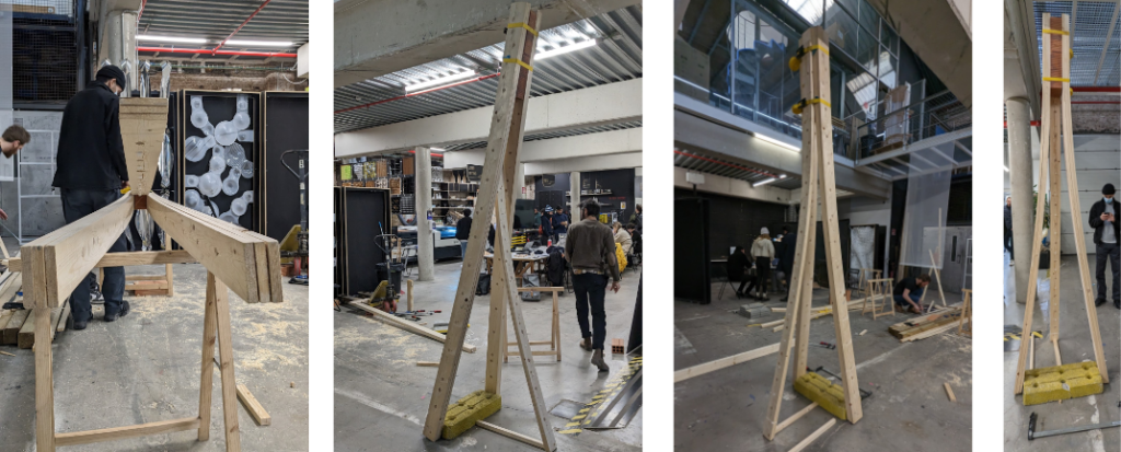
Column to Space
…
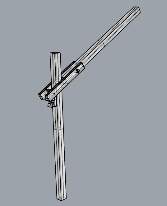
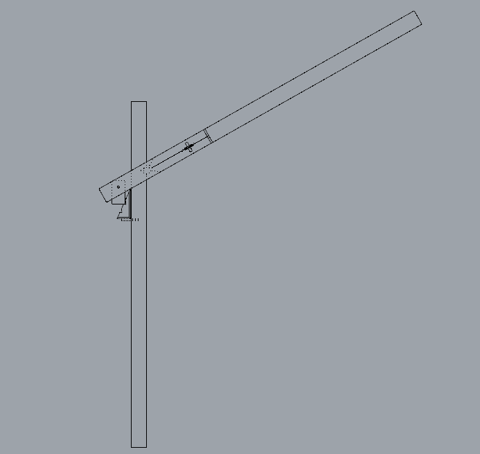
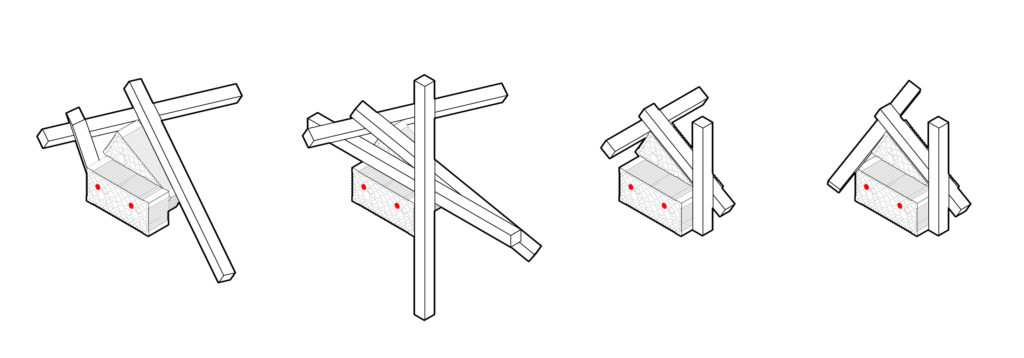
Kinks
During the studies of wooden structural kinks, we had to make several prototypes of the joints of wooden beams 45 by 45 mm with variable angles and fixed angles. As a material, we used: 45 by 45 timber and 45 by 20.


Type A Fixed kink
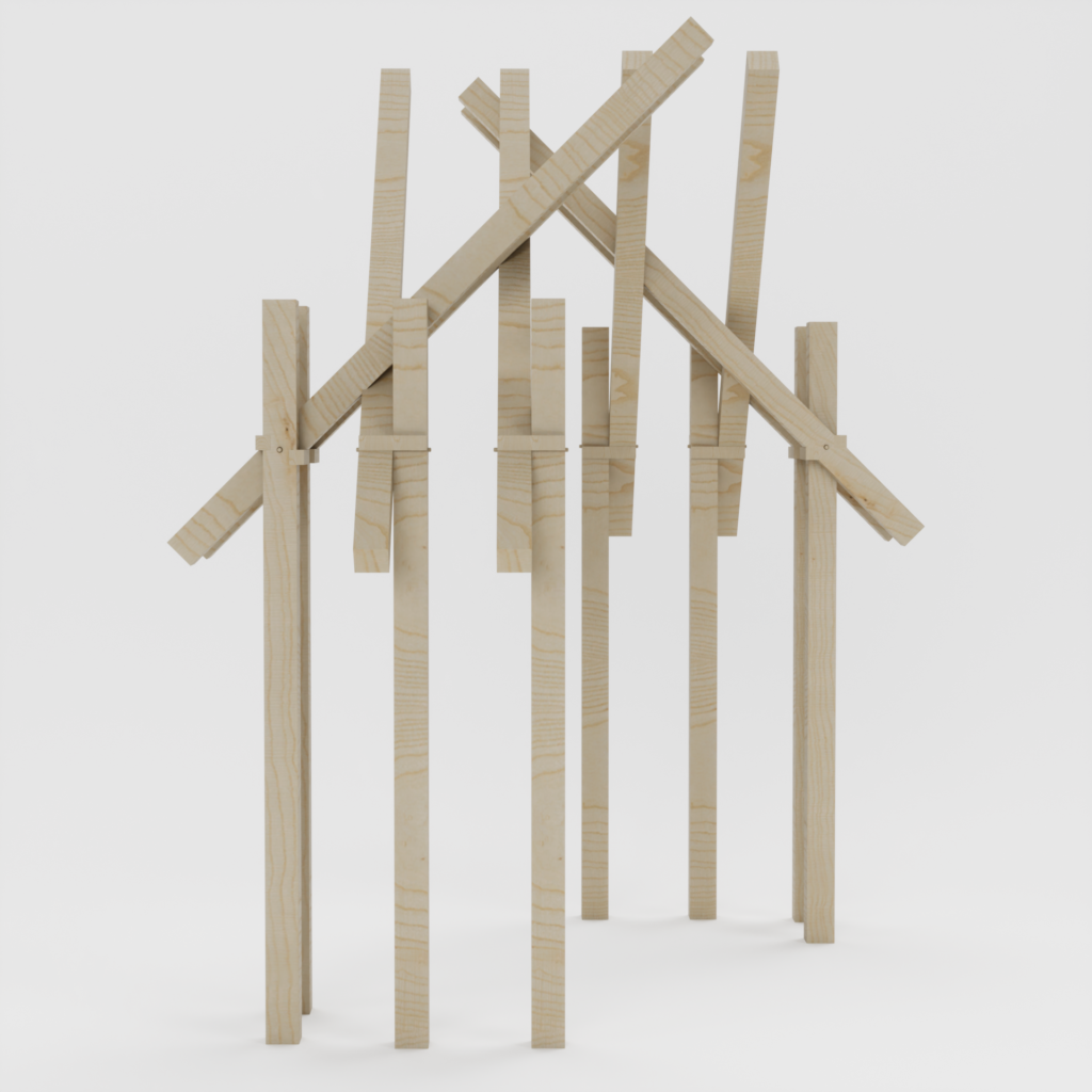

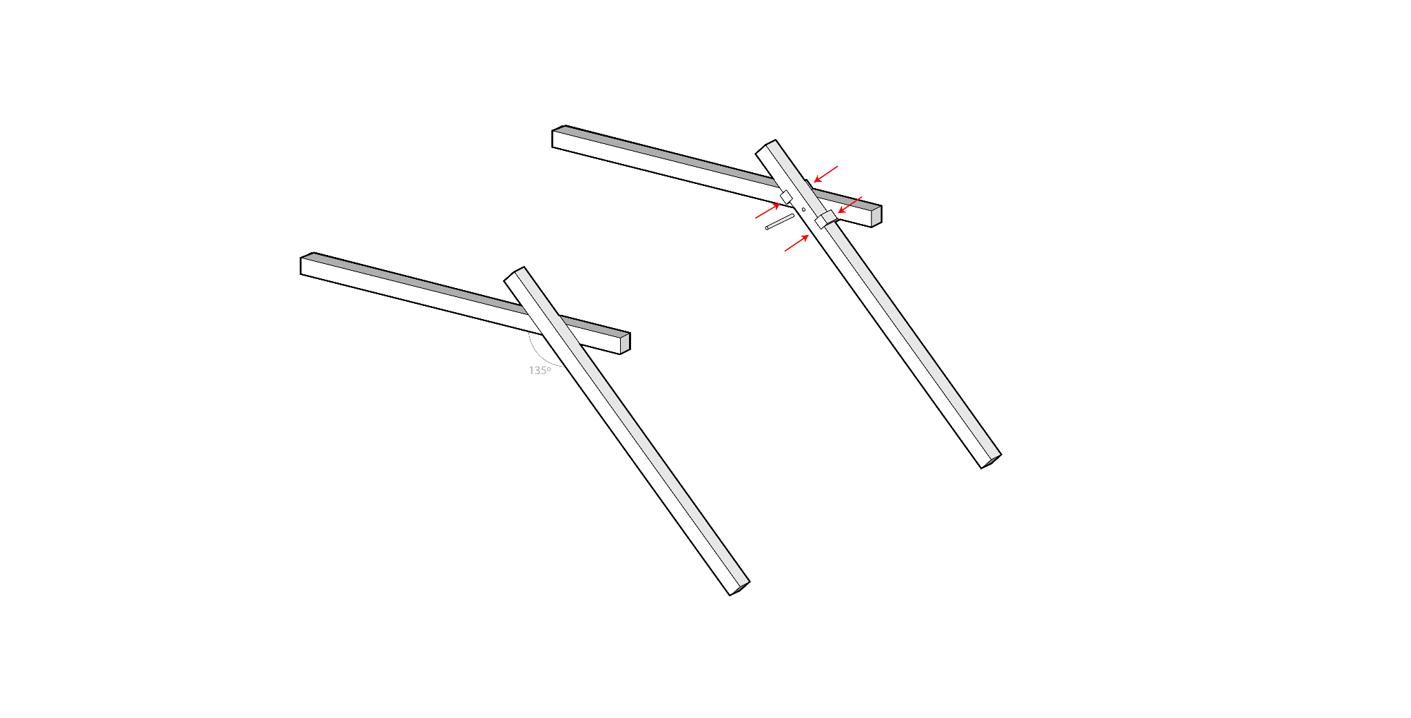

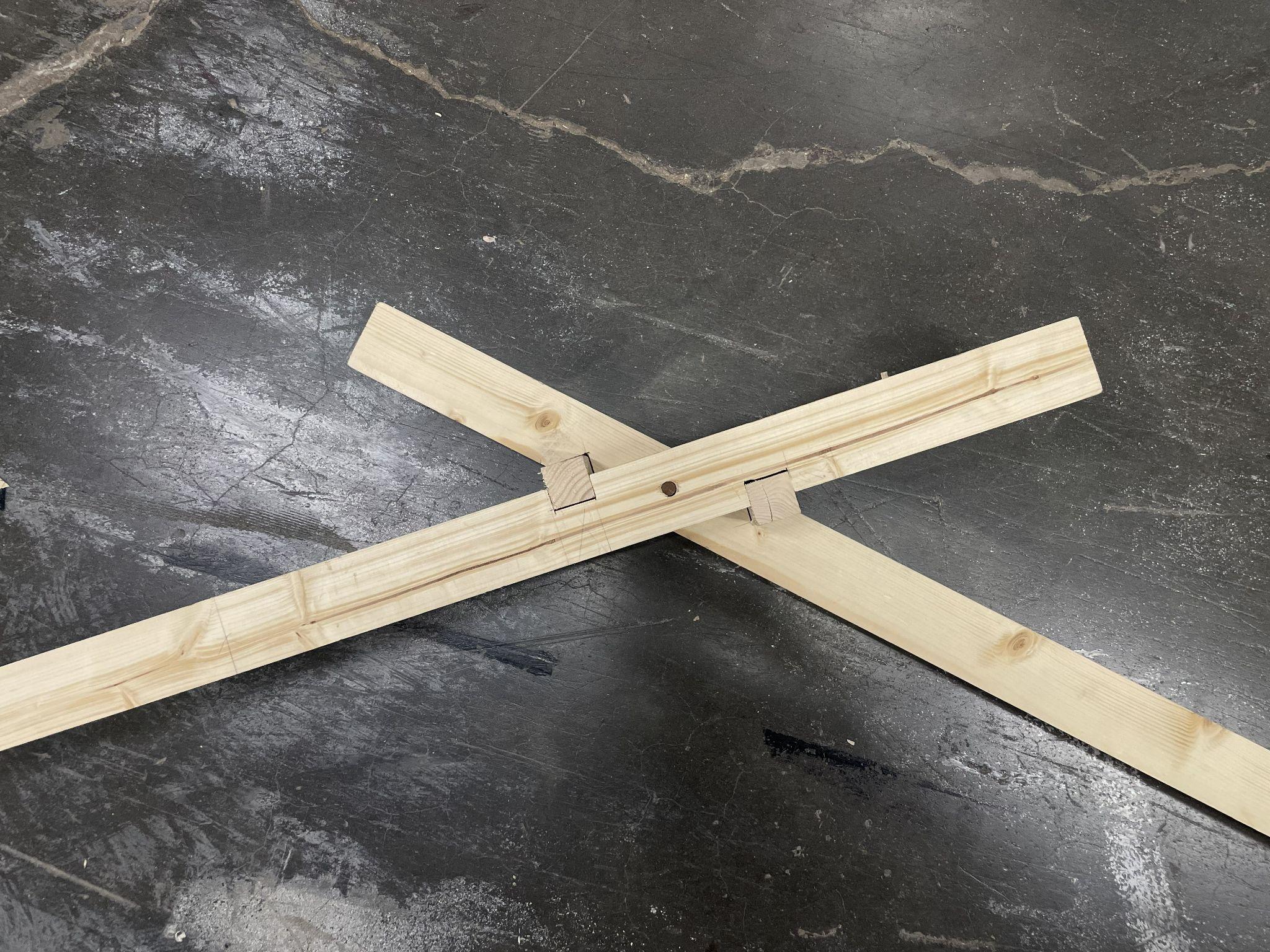
- Square Shear Keys
2. Wooden dowels
Type B Changeble kinks
…

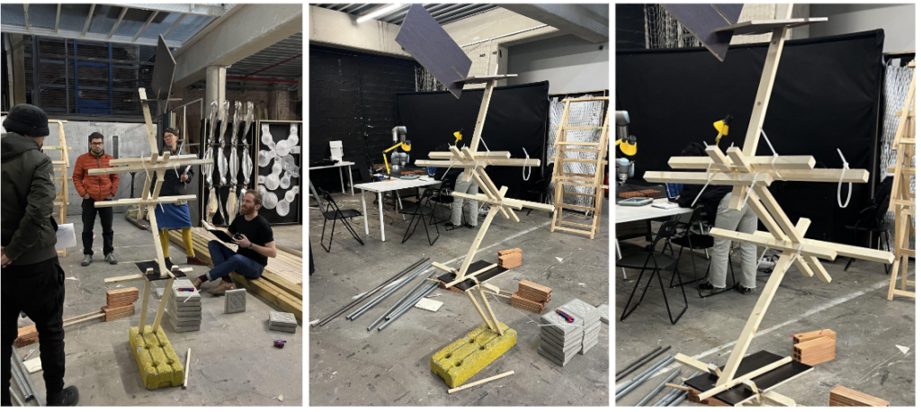
Counterbalancing kinks:
Conclusion:
_Positions of shear keys and wood cylinder locks
_Lengths of wood cylinder locks
_Shapes of shear keys
_Diameters of wood cylinder locks
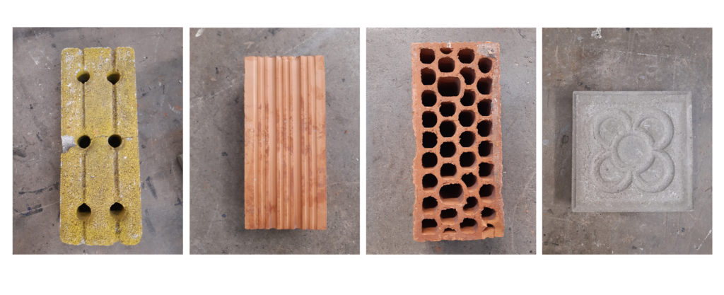
Bricks
?n order to understand the materials, their properties and mainly their weight for the creation of the base of the construction, we experimented with Concrete footing, types of Bricks and Pavement tiles. Base on the logic of the counterweight we initially created 4 types of bases embedded in a perimeter of 800*800mm.
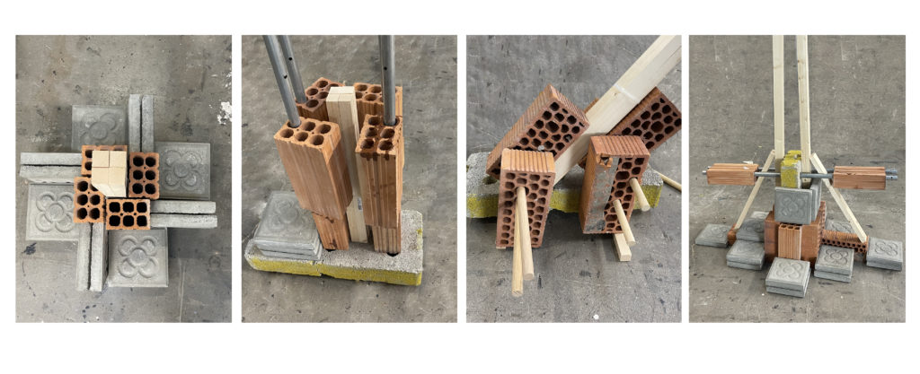
Type A Vertical stick around only bricks
Type B Boundling vertical bricks holes to fix the angle
Type C Bundling horizontal to create different orientation
Type D Weight to clamp
Evaluation:
Type A
The contact surface of ~123,75 cm² between the wood column of 45×45 mm and the brick improves the force transmission between the two components.
The system benefits from the transfer of high clamping forces between the soft pine wood in comparison with or to the hard wall bricks.
Type B
The vertical alignment due to the internal steel connections allows rotation around each axis of rotation in the Z-direction. In addition to high the claping properties, the system allows an extension of the structure depending on the axis of rotation of each brick.
Type C
The rotation of the bricks from their original plane of use and the combination with further bricks, which are then connected with wooden dowels, allows a combination of different angles. On the inclined bricks surfaces, which create new planes, the wooden elements can be rotate on these planes. The system benefits from a high number of variable angles, which can be achieved on the one hand by the combinations between the bricks and on the other hand by the additional rotation of the wooden elements on the new planes. The combination and connection of the two building materials, wood and brick, in this system was examined more closely because of the potential for spatial expansion and the ability of reasembly in a new modular combiation.
Type D
The physical exploration goes into the use of the dead weight to improve the static structure through clamping properties.

Type A Vertical stick around only bricks
Type B Boundling vertical bricks holes to fix the angle
Type C Bundling horizontal to create different orientation
Type D Weight to clamp
Angled Connection: Bricks Possibilities
The combination of bricks and wooden beams is presented as very advantageous: a wide range of angles is possible only by connecting the right holes between brick-brick. Studying one by one all the various possible angles, are presented below the main ones that allow the connections between the various beams.


Thanks to the angles obtained by combining the perforated bricks and fixing them through wooden connections through prefixed holes, you can fix the beams and get different combinations. The following image summarizes some of the main combinations and connections obtained.
Shear Keys & Connections
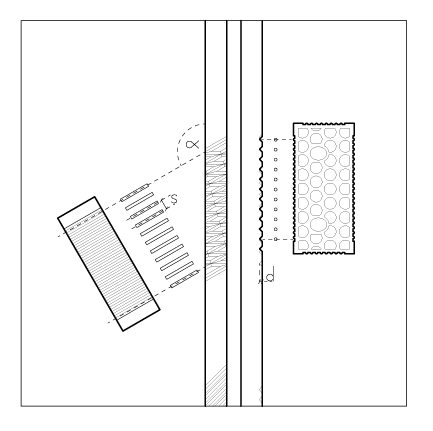
CNC Setup Parameters for Shear Keys
The angle ?, which determines the orientation of the wood on the cricket, is variable.
The cutting depth d of 7.5 mm was matched to the texture of the brick and the round shear key with a diameter of 8 mm.
The distance between each shear key s was set at 21 mm.
For the CNC cut a VeeMill45 mill bit was used.

Evaluation:
The CNC texture allows different angles to be created between the wooden component and the brick. The overlaying of different angles of the CNC-cut textures allows further connection variants for later re-assembly. Using VeeMill45 also has positive effects on the later recombination and reorganization of the wood elements. In specific, the shape of the texture can also form a notch for 45 degree connections as a static support. The connection of wood and brick by shear keys allows a combination of the different material properties. The force-transmitting and shear properties of both materials can be combined in the nodes. While the wooden elements act as linear load transfers, the brick as second component can absorb acertain a mount of torque and shear.

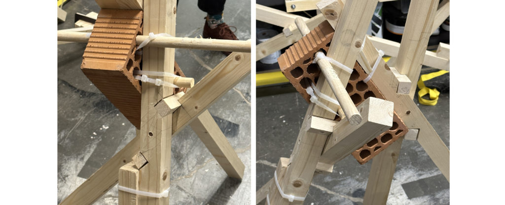
Middle_Wood dowels as rotation anchors. CNC texture as notch. Brick holes as leashing fixpoints.
Right_ Adding shear keys after tightening the tension strings in the prefabricated texture increases the pressure between wood and brick
Connections
In the explored connection system, bricks, wood and wooden dowels can take on different tasks. The connection between wood and brick was made with plastic zip ties. The zip ties form a tension-based connection. This manually created connection is not only reinforced by inserting the shear keys after pretensioning, also, the application of force perpendicular to the shear key direction increases the stress in the tensile joint, thus making the joint stronger to a certain degree.
Kinks & Bricks

Conclusion
Position 3 Planes of Rotation
Brick Holes 2 Planes
Dowels as Brick alignment and leashing fixpoint
Wood roughen increasing surface area for interlocking
Shear Key as a wedge increasing tension based connection
Curves


Conclusion
_ spring back major change in deformation when the constraints are removed (especially on thicker wood sections) probably due to the use of softwood
_long cracks on the wood especially on the thin lamelas
_connection with the bricks makes it into a really stable structure
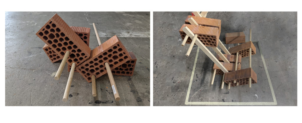
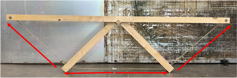
TRUSS
Configuration for angled joint
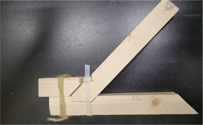
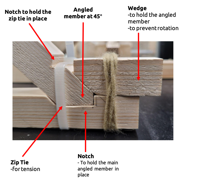
Truss type 1 // On a single plane
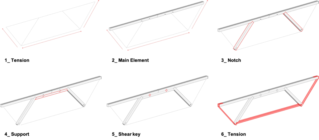
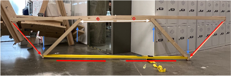
Truss on 1 plane
Working on tension by the angular belt ties and compression on the horizontal bottom attachment by using the ratchet belts pulling both struts together since its notch with the beam at the top part and the center element with the shear key attached to the beam it generates a compression between the two elements due to the counter load


Truss type 2 // 3D
Truss on 2 planes Working on tension connected by rope simulating metal tensor cable;
Connection by triangular shear key attaching everything together;
Zip ties attached to the 2 planes;
Metal thread rod connecting the two planes and tensioning the rope;

Final Truss Timber+Bricks
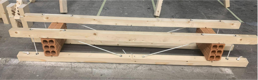
Ball bearings
Dowel as shear key holding bricks and timber together preventing horizontal sliding movement
And tension zip tie for preventing shear
Rope working as post tension elements
Conclusion
_ Shear Keys By using 2 planes it allows the truss to attach complementary elements to work as
shear keys ;
_ Combine! By combining the shear connection with gravel and tross it was possible to build a
beam without using bolts;
_ Main Challenge was to adjust all of the ropes at the same time;
Design – Parametric design
Design – Wood and Brick
From Complex to Simple
Reference

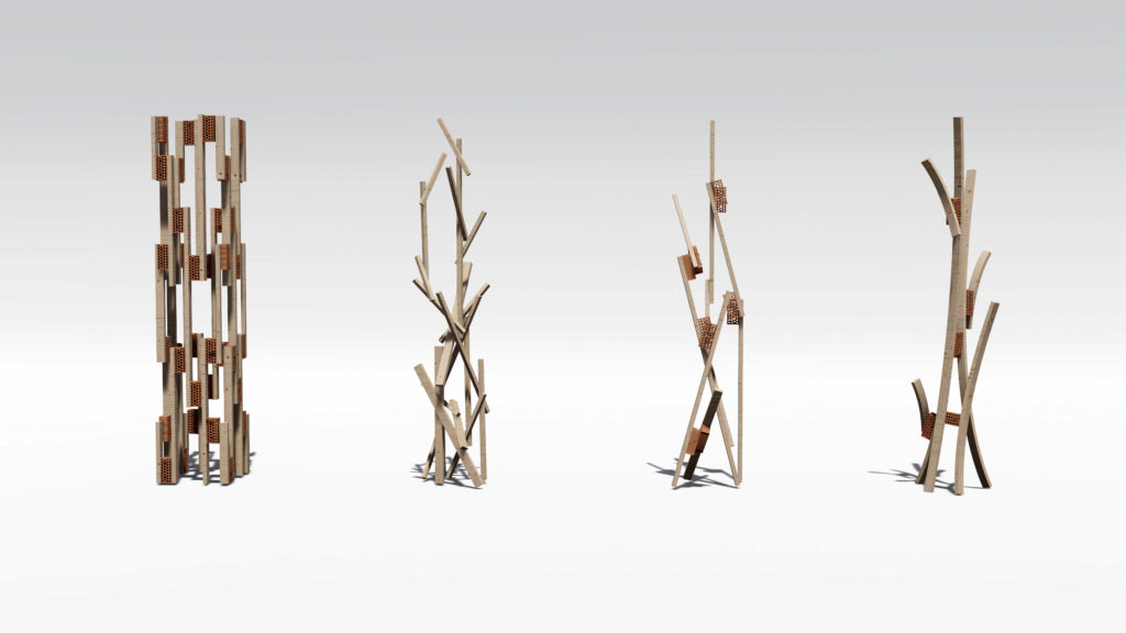
Column Design

How to define the boundary of the column?

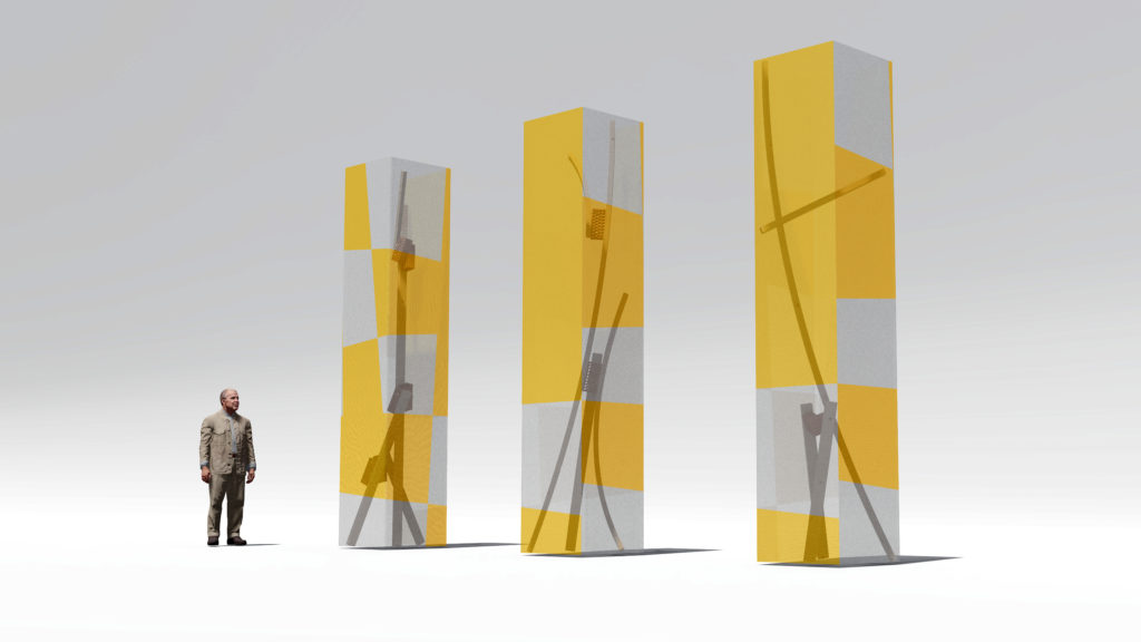
The Bounding Box Opt 01 – Pet Sheet / Wave Texture Glass


The Bounding Box Opt 02 – Recycle Fabric

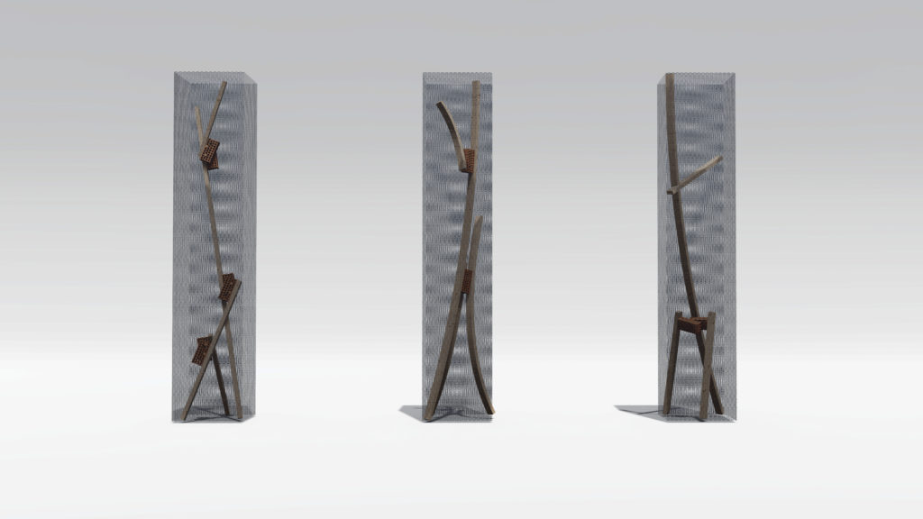
The Bounding Box Opt 03 – Metal Net
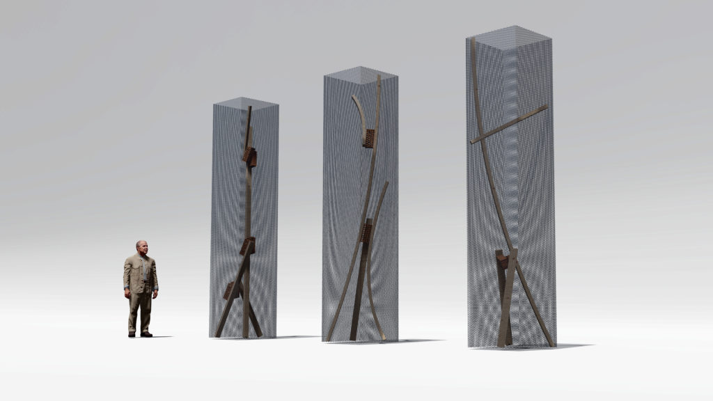
Serial Design of The Columns