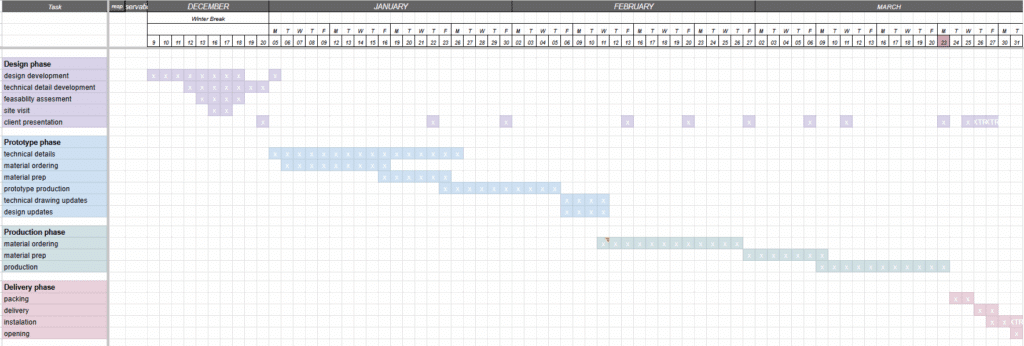
Building on our previous analysis of a large clay-printed geometric form, this study evaluates the feasibility of its digital-fabrication workflow. Through modular breakdown, material and time estimation, non-planar slicing analysis, and production-logistics modeling, we assess whether the system can be manufactured efficiently and economically. The process concludes with the development of a complete production plan structured as a Gantt chart.
.
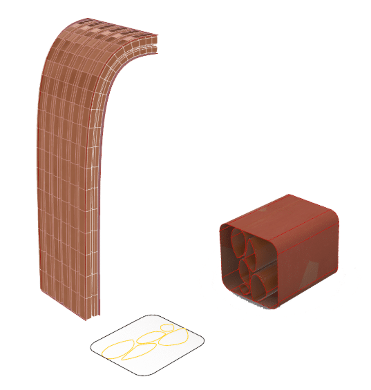
The first step for this task was to again, create an section of the final arch design. Then we create an infill which would go along the arches curvature. Using an inner and outer shell we create a box morph as explained on the next page. This is to follow the curvature path whilst not deforming the infill bricks themselves, since these are what we are printing. Any deformation to the mesh of the infill will heavily affect the printing stage so this allows us to manipulate the geometry without affecting the toolpath of the pieces individually. We then create a rectangular grid to start the organising and second logic step.
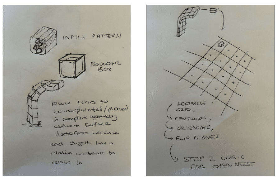
We structured each infill unit inside a bounding box to manipulate it along the curved geometry without distorting its printable form. This ensured consistent toolpaths across all modules. Next, we arranged the modules on a rectangular grid, using centroids and plane reorientation to prepare them for OpenNest. This allowed us to efficiently organize the pieces for fabrication, packing, and transport.
.
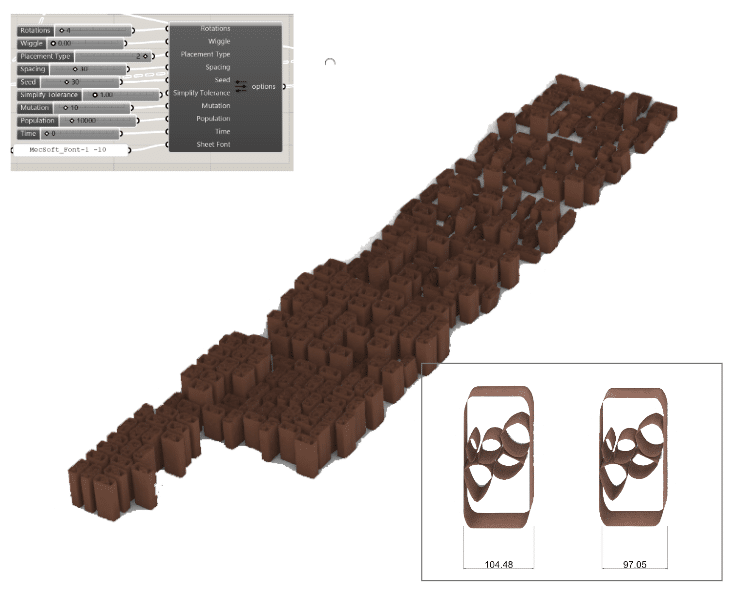
As if we were moving into the production of the pieces we next start organising the pieces The first step is to produce rectangles simulating pallets. By seeing how much area we will require we can start thinking about the packing and transportation of the prints whilst still in grasshopper This part of the script also takes into place for shrinkage in post production by using the scale component Lastly this logic step also includes to look at the non-planar slicing for the pieces.
.

.
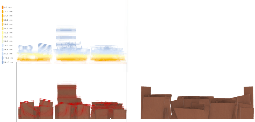
Before moving into the Gantt chart and planning production we can check the design by using analysis tools for the slicing and checking the angle of the slice planes. From the angle analysis we can instantly see some of the prints have heavy initial angles which could cause collapses in production. To avoid this we can increase the number of divisions in the curvature via box morphes to reduce the angle and print smaller objects. Alternatively, we could change the curvature of the design. Since the angles are not so extreme we could tell the robot end effector program to be more precise whilst printing these pieces or place supports for these elements.
.
.