This project, approached as a demonstrative project, was elaborated by Group 8, Anna Irene Del Monaco and Athanasios Vagias and worked on multilevel Timber structure.
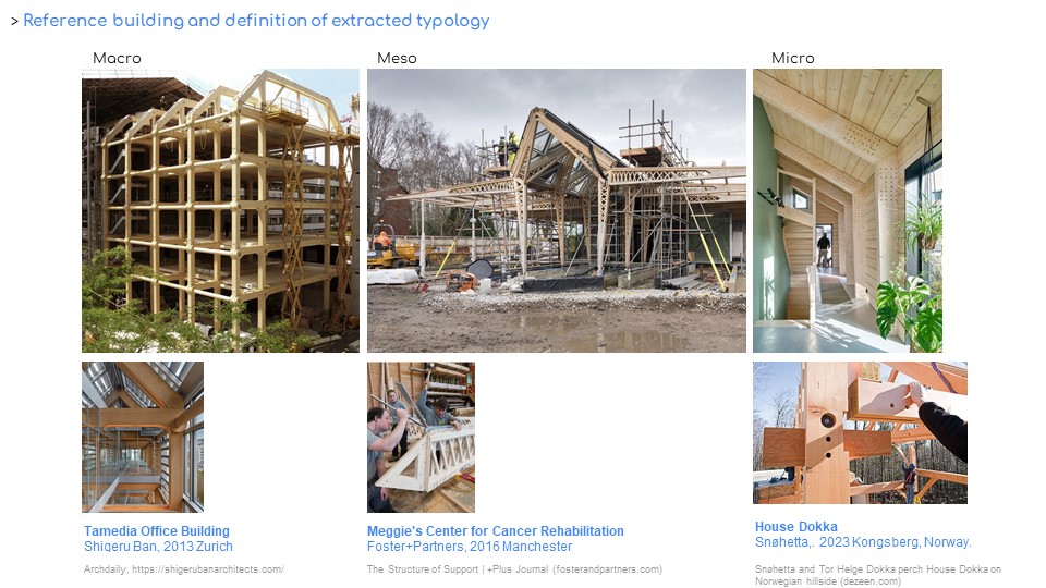
We started investigating precedents on timber skeleton structure. Our initial interest fell on the Maggie’s center by Foster and partners for the masterful creation of a refined structural node in timber lattice with CNC technologies. Then it came our research question! To what extent is it possible to shift the qualities and the character of Foster’s project to a multi-level building? And at what cost!? And to obtain what design result!? Therefore, it was useful to study Shigeru Ban’s project in Zurich, implemented by the same manufacturing company. In the final part of our work Snohetta’ s project without nails structure for a ordinary building (with respect to Shigeru Ban case) helped to study our structural node.
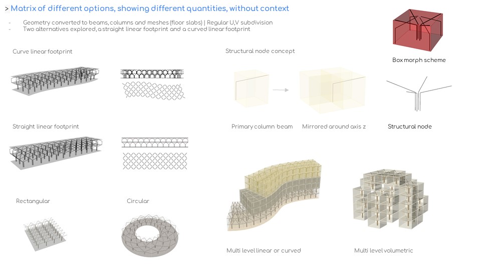
The input of the system is a curve. It can be open, closed (for example a circle) linear or curved. From the given curve, a loft surface is created. This is the footprint of the building structure. By using an attractor point, the width is reduced in areas less material is preferred. Then, the surface is divided in U,V direction, in equal cells sizes, or by the use of graph mapper, in variable sizes. This is also to achieve a densification of structure or on the contrary, a lighter system. Next step is the creation of the voxels. An array in Z direction defines the levels. By managing the tree data structure, we control the organization in brushes so that each voxel has an ID: A-floor number, B-position in U, C-position in V and D-design strategy. Parallel to this process the structural module is define and then applied to the voxel grid.
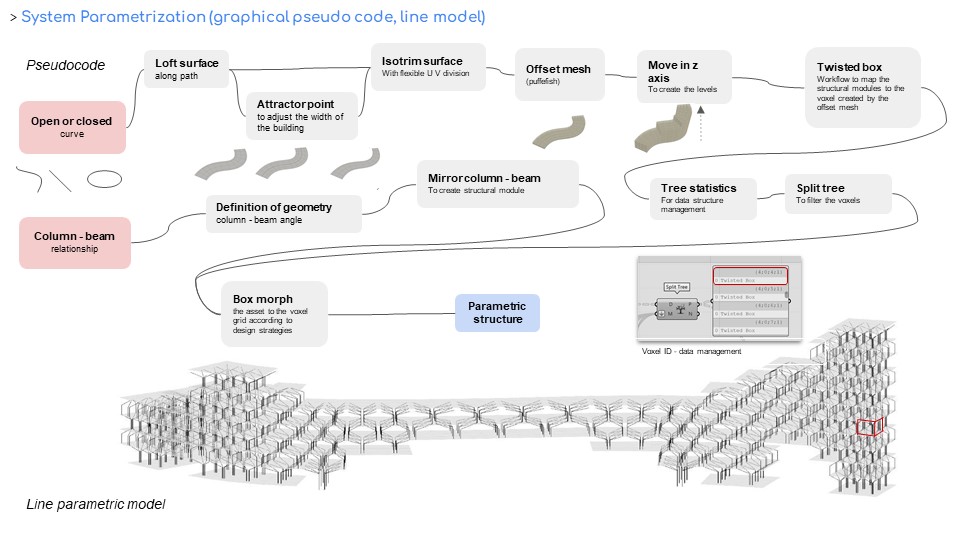
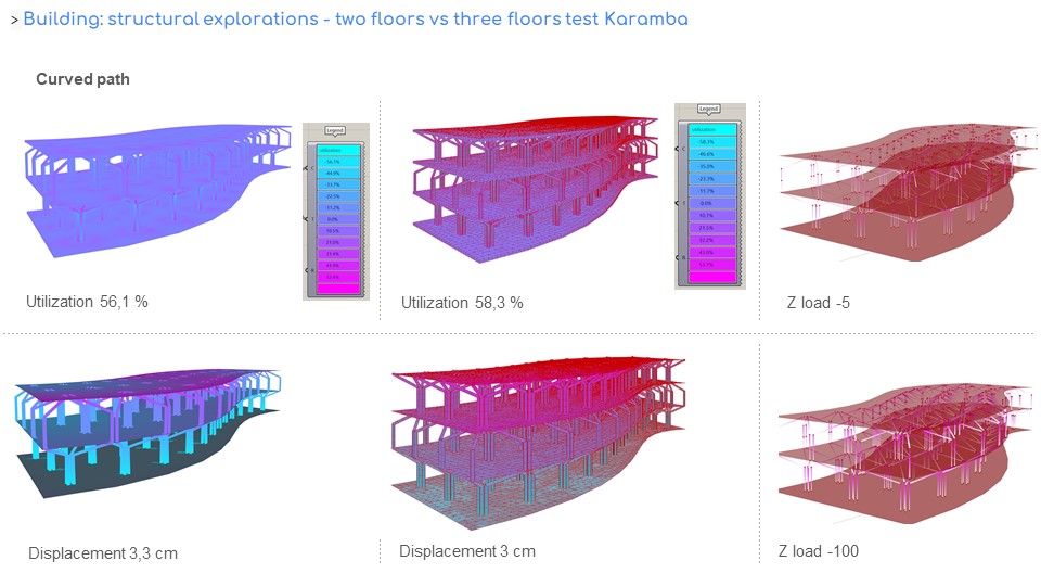
This computational process results in a flexible structure where – floor, height, area and structural module configuration can be easily adjusted. We tested the linear path in two floors, the curved path – difference between them is that beam lengths are a lot more varied in the curved structure. A demonstration of changing the footprint of the path with the gif clips reflects the malleability of the system. One or multi floor, with terraces or with an interior void/ atrium. The structural node draws inspiration for the precedents. Repeat the same node every other floor, resulting in a “beehive structure”? We explored the structural performance of the system with Karamba, starting with only two floors. When we added one more floor, the utilization improved, and the displacement decreased. Both are positive results- meaning a suitable system for multi-level buildings. The tests included also buckling analysis for a Z load of (-5 and -100). By adding a third floor to the curved alternative we realized that utilization is actually improved to 58,30%. And displacement not really affected 3 cm.
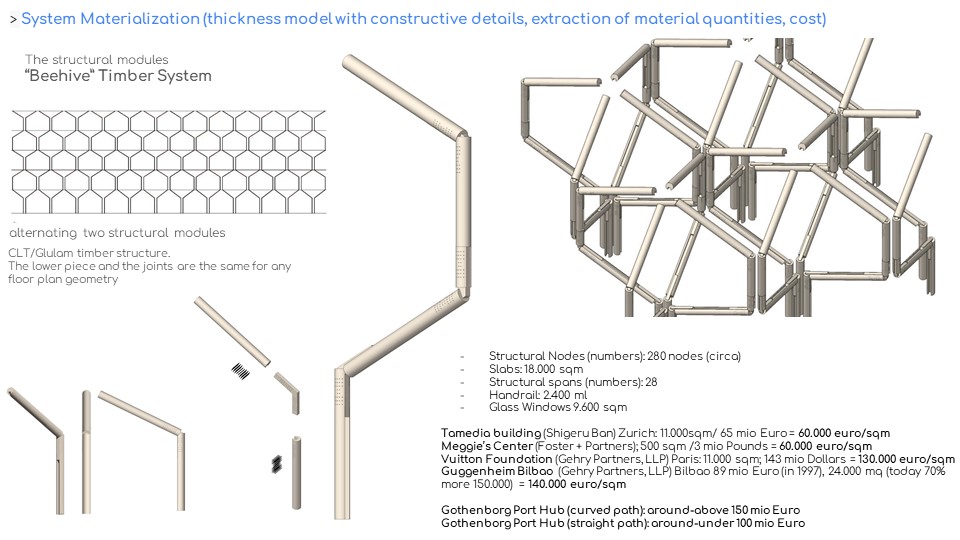
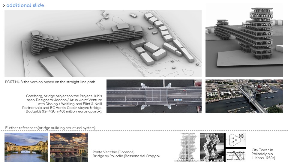
Once the structural model was identified we started investigating its translation into a construction system considering that the use of different paths could affect cost and complexities in design and construction. Therefore, we design a structural node and joints without nail (as in the case of Snohetta) so that at least the vertical module and the joint can be repeated in the curved path while the diagonal elements need to be adapted to the grid. On the contrary in the case of a linear path the module, the structural node and the joint can be the same. The costs of the project have been investigated on a qualitative base comparing the surface of sqm and the complexity of the construction of Port Hub with other well-known projects.
The calculated structural performance, with the help of Karamba 3d, resulted in specific cross-section. Below the structural node connection details are presented.
The site we selected is in the old industrial port area of Gothenborg.
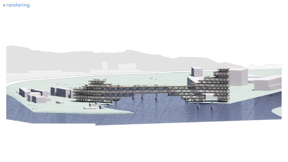
Today it is an area under development where several master plans were elaborated in the last years to demonstrate the potentiality of the area. The old harbor hosts now student housing units, a park and a sauna. Even though it is in the center of the city, the area is disconnected, by being passed by. The decision to propose a bridge building is both strategic and symbolic: A bold move for place making and a connection between the port piers. Therefore, we proposed a bridge-building instead of a traditional bridge: extending urban connections and improving the qualities and urban value of the area.
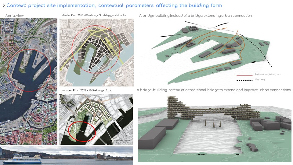
Then, the script was tested with a linear path input and worked out. It is important also to recall that in the same location to implement the master plans mentioned a bridge project was elaborated for an estimated cost of 400 million euro. So, the Port Hub proposal represent a possible base to build up an alternative to integrate a bridge and a building.
The site we selected is in the old industrial port area of Gothenborg. Today it is an area under development where several master plans were elaborated in the last years to demonstrate the potentiality of the area. The old harbor hosts now student housing units, a park and a sauna. Even though it is in the center of the city, the area is disconnected, by being passed by. The decision to propose a bridge building is both strategic and symbolic: A bold move for place making and a connection between the port piers. Therefore, we proposed a bridge-building instead of a traditional bridge: extending urban connections and improving the qualities and urban value of the area.
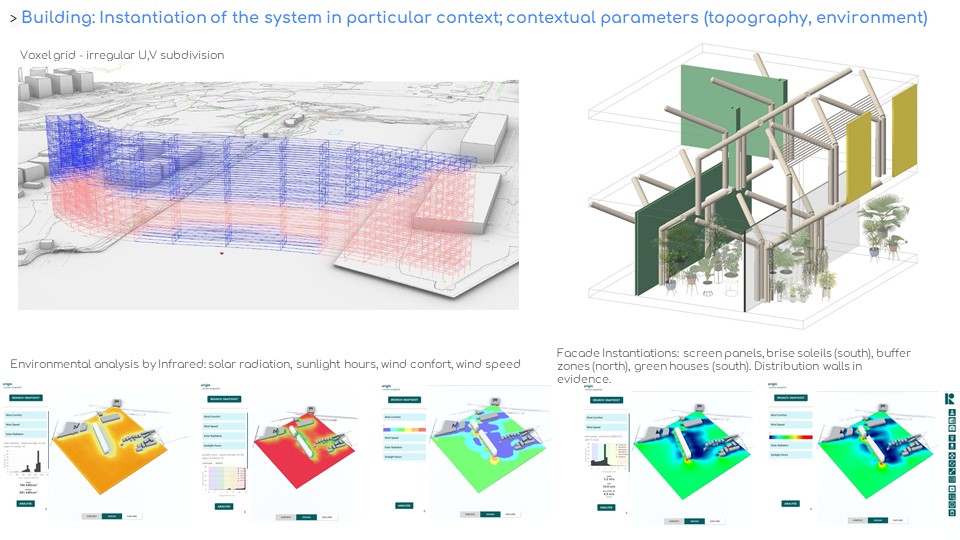
Having decided the placement of the building, the curved form, and the maximum height, we employed environmental strategies for “sculpting the voxel grid”. Light structure in the middle, letting the wind pass by smaller volume in the west, to match the scale of the existing context – which is student housing. On the east, the volume rises high, to protect the old pire from dominant southwest winds and mark the building’s position. A hybrid form, half block, half bridge acts as a valuable addition to its contexts. The design of the façade includes buffer zones and green houses in the North and screen panels, brise soleil in the South.
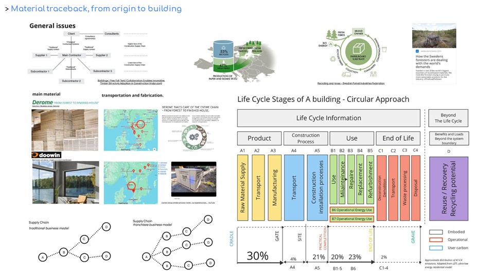
The project was conceived and developed considering the use of two primary construction materials: timber frame as a structural system and other finishes and glass facades. Two companies were identified in the area around Gothenborg useful for the scope. The life cycle analysis was carried out considering the elements described.
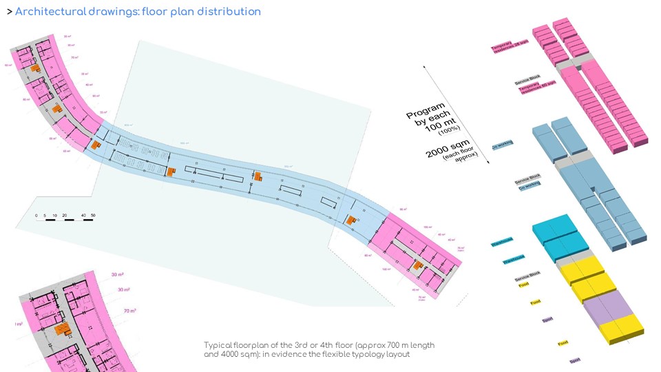
A typical floor plan was elaborated for the more extended floor of the curved path building proposal. With a length of approximately 700 linear meter and a cross section of about 21 meter the building presents flexible typological options with spans from temporary residencies to office spaces, co-working spaces, warehouse, storage and exhibit space.
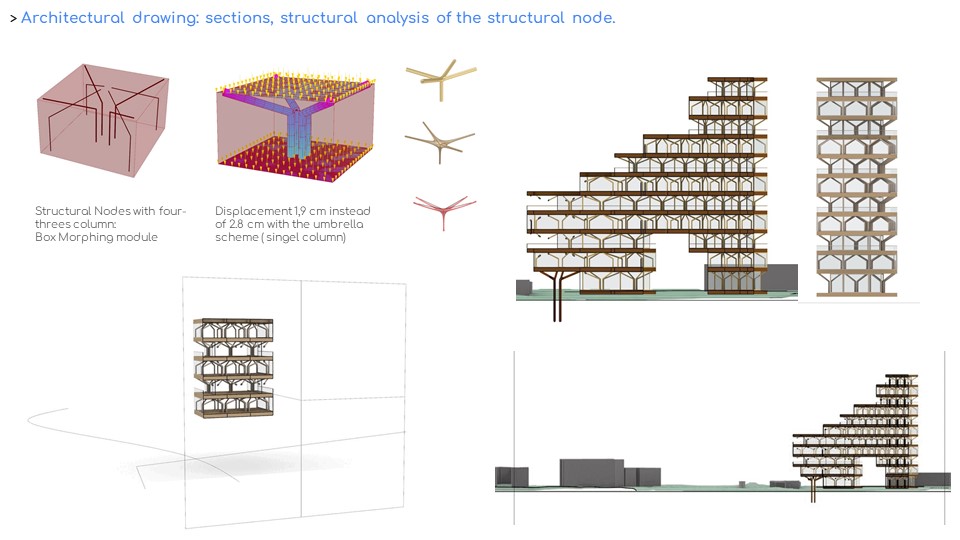
The versatility of the system starts from the footprint definition to the structural node. The sequence of the consecutive cross and longitudinal sections gives a glimpse of the building’s architectural qualities and character.
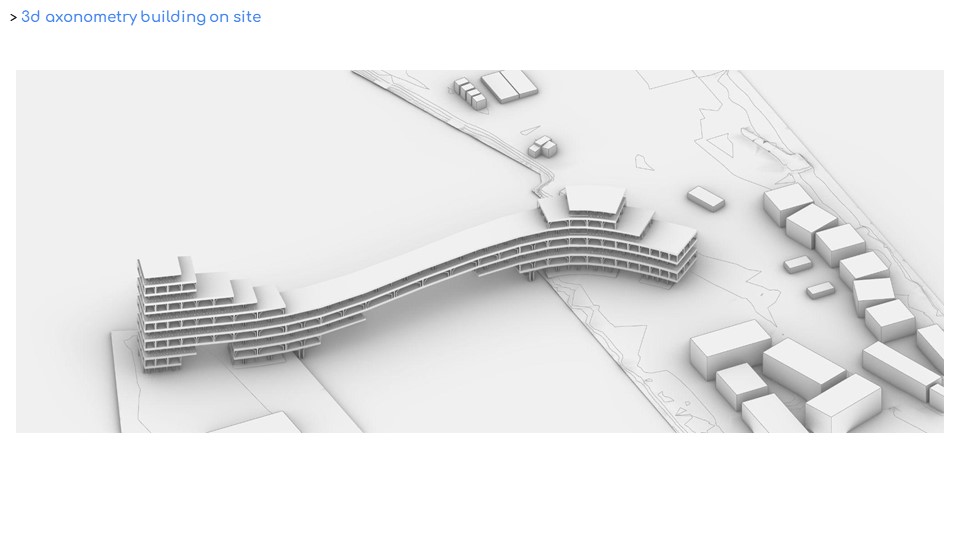
The axonometric drawing displays synthetically the general volumetric masses and the hybrid quality of the project, representing either a building or a ship, or a bridge. The following renderings demonstrate the potential role of place making that the project Port Hug would be able to activate in that precise area of the city not far from the city center.