Geometry’s Infills as a resultant of fiber support strategy for cantilevers, envisioning the gesture of enclosing a spaceInfill geometry as a resultant of the fiber reinforcement strategy, envisioning the gesture of enclosing a space
Geometry‘s Infills as a resultant ofthefiber support strategy for cantilevers, envisioning the gesture of enclosing a space
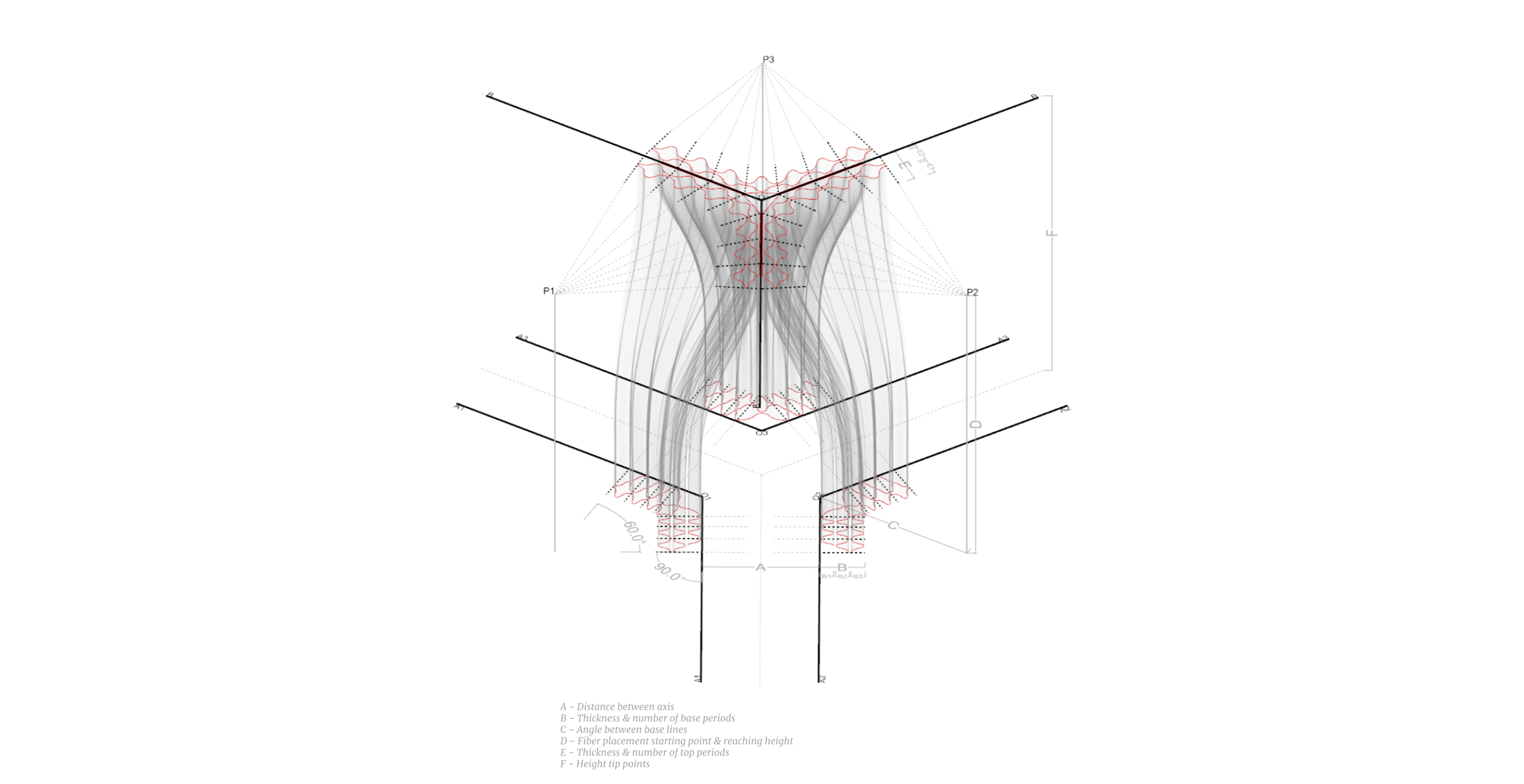
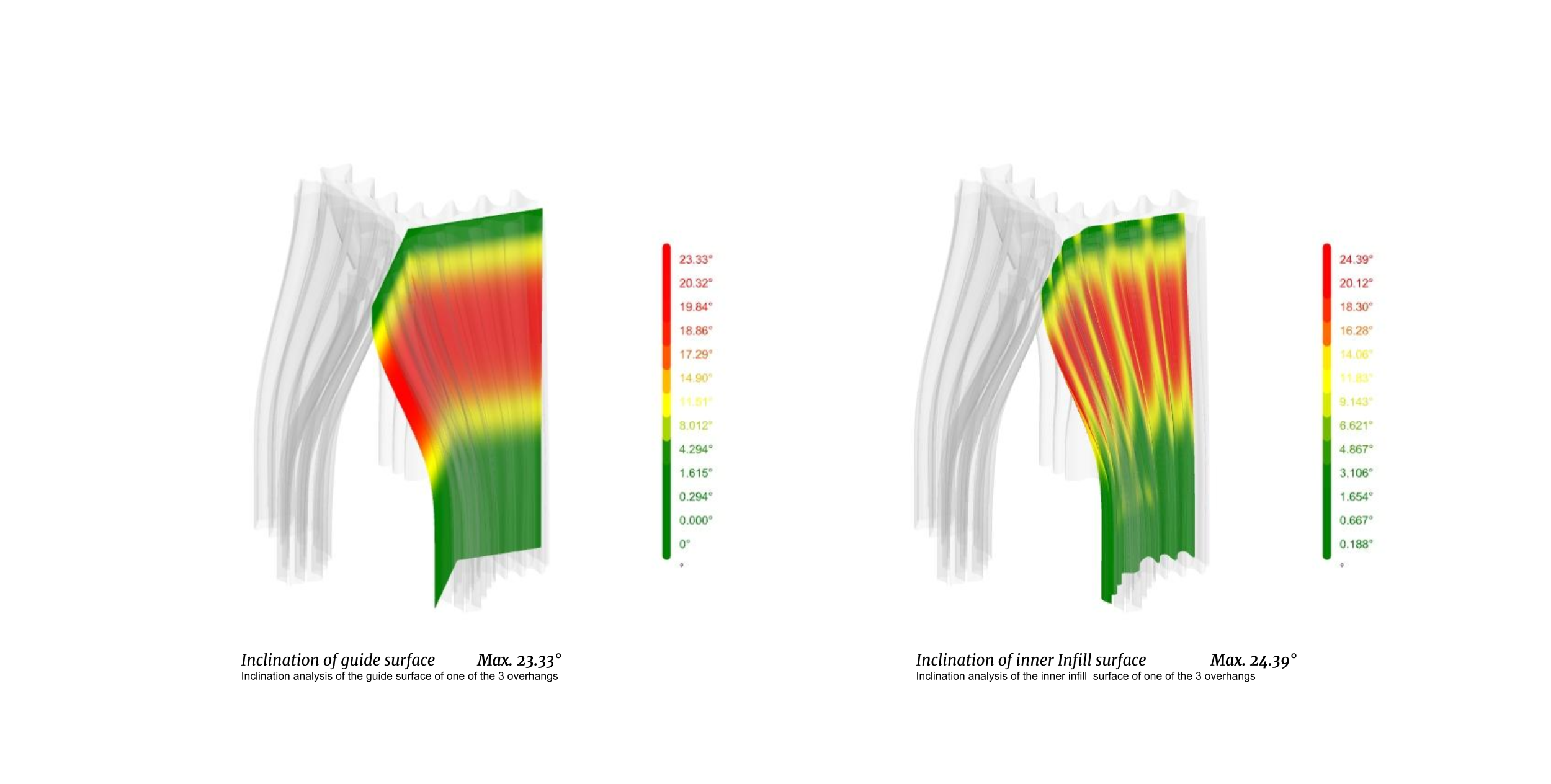
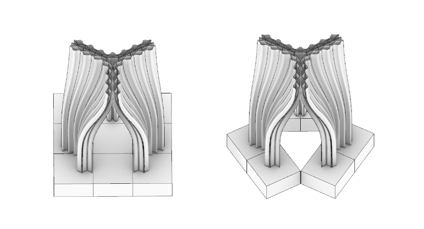
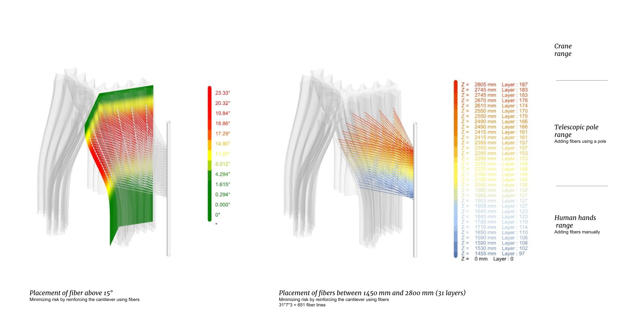
Three symmetrical generative axes were considered that reach the top, meeting in the same origin. Altering parameters such as the distance between the base axis, the inclination reaching the top and the height of the top axes, the geometry is considered in a shape which is achieving a controlled inclination of the guide surfaces of ca. 25°. Minimizing the high risk of material displacement and buckling, and achieving this inclination degree was enhanced with a fibre placement strategy. Inclination analysis showed where slender risk is the highest and fibres tensors placed while printing for inclination higher than 15°, previously reaching 10° more than the material proved limit of a 1:1 large scale clay print.
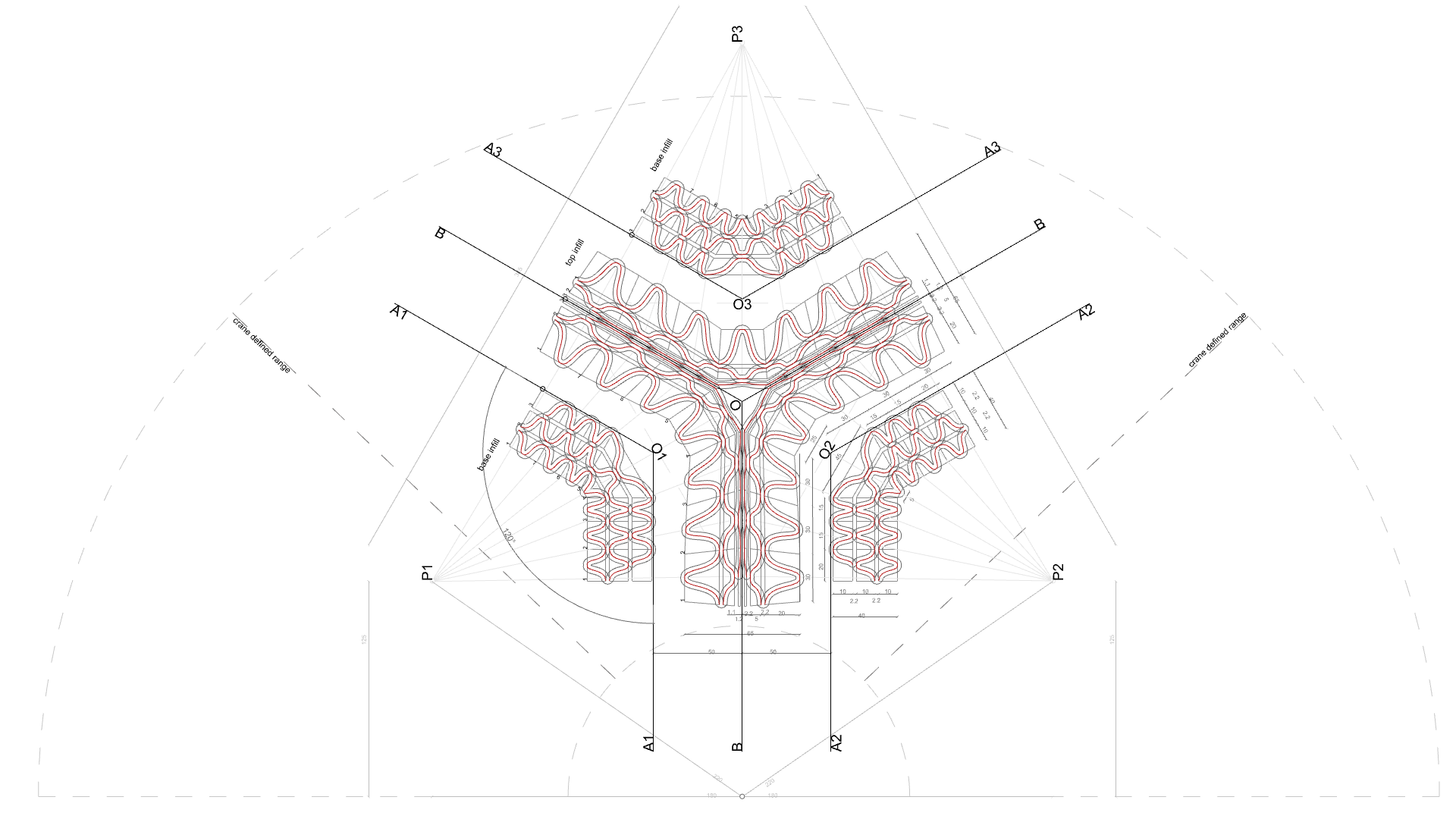
For every lofted side surface a corresponding pole was designated, and the cables were laid on a radial position revolving around the poles points. These directions generate the direction of the infills’ bounding boxes, the whole surface responding to the direction of the cables, placement of the fibers is considering the tangency points in between the designed periods. Hence, the infill geometry is a resultant of the reinforcement strategy.
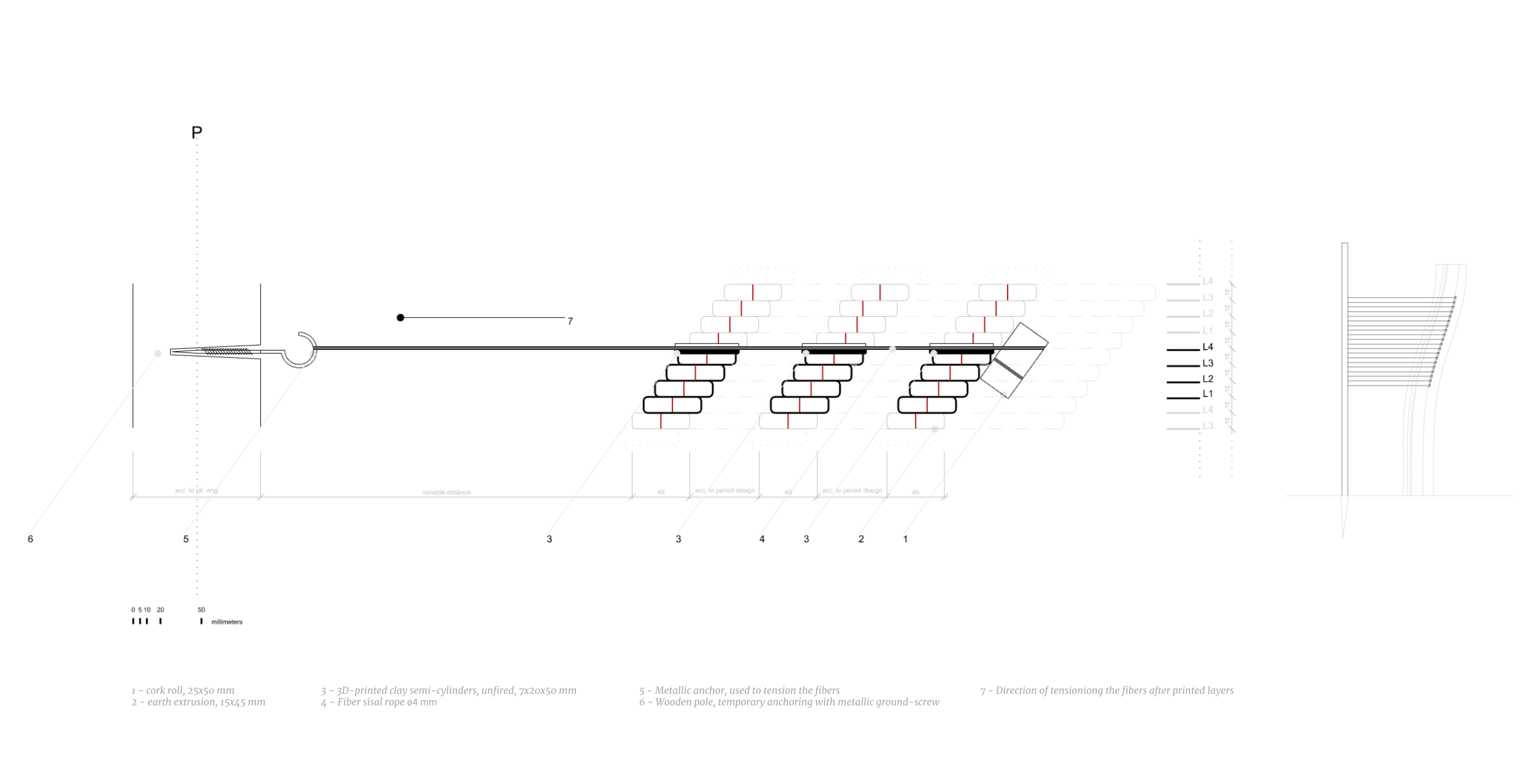
As design detail, the fiber tensors are placed according to the analysises every couple of layers and consists in fiber cables with a cork-roll anchor, the cable is laid on the earth-material extrusions. The tensioning of the fibers is taking place after printing another couple of layers. To avoid deterioration of the print while tensioning the cables, in between the fibers and the earth-material, 3D-printed clay unfired semi-cylinders will act as washers to disperse the forces. Unfired clay will create a proficient bind with the extruded material, preserving the humidity, nevertheless, resisting the friction forces determined by the fibers, alteration of the clay occurring in time. In tandem with the shrinkage of the earth, the clay will be embedded as a design detail.
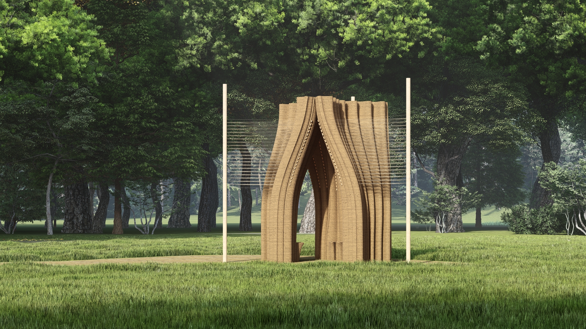
A passive strategy of successfully reaching the top and enclosing the space as weight decrease proportional with the height of the print. Merging infill layers at the key-vault to minimize material use while maintaining local and global inertia, a visual smooth transition was obtained from merging three full width periods to two variable width ones.
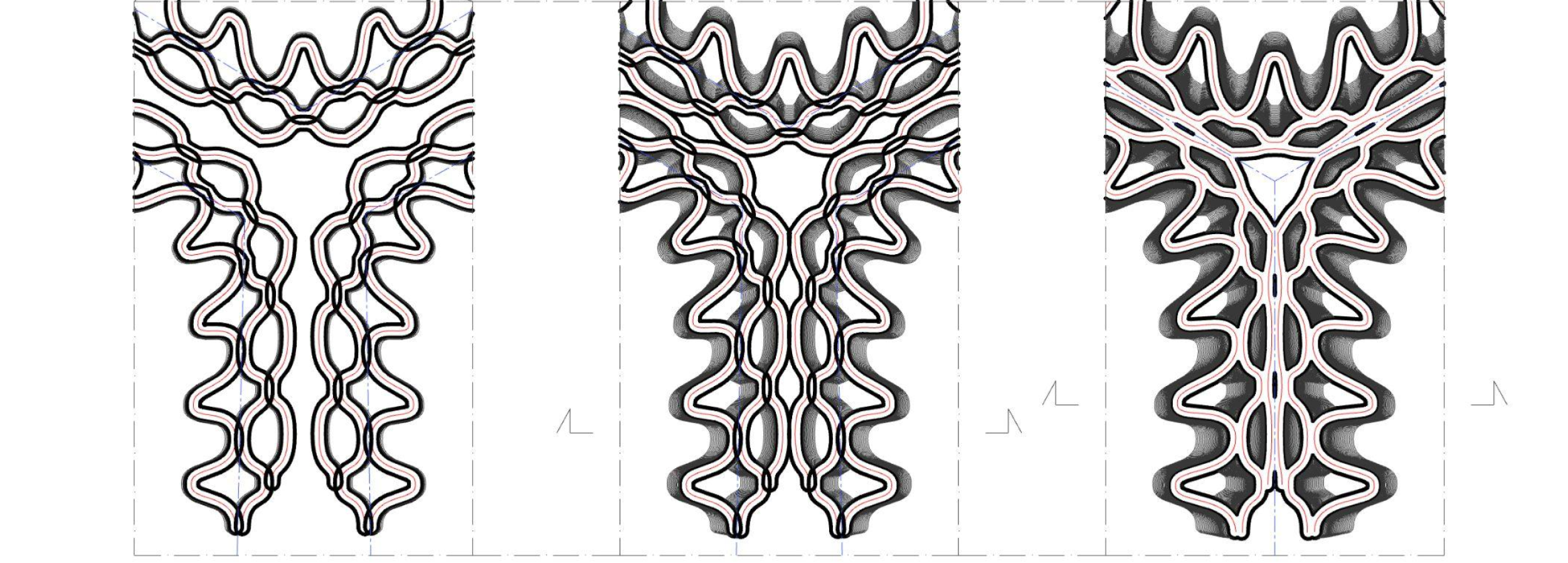
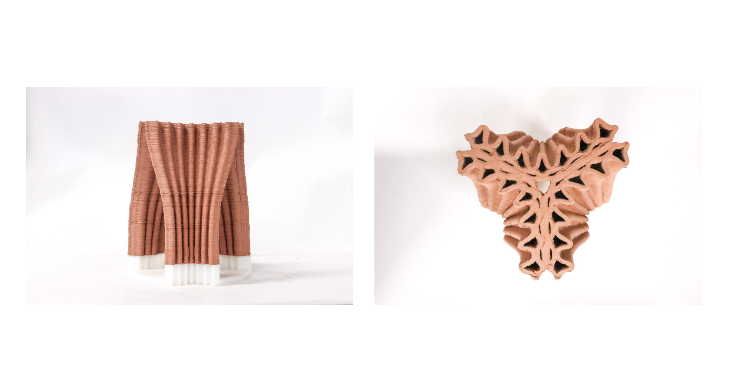
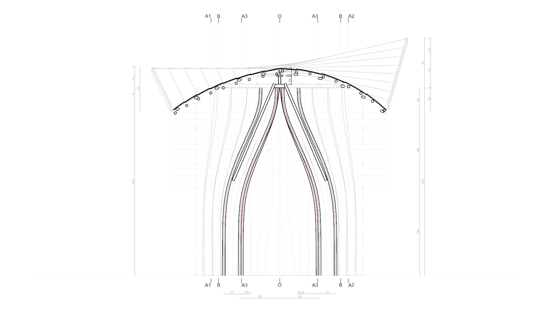
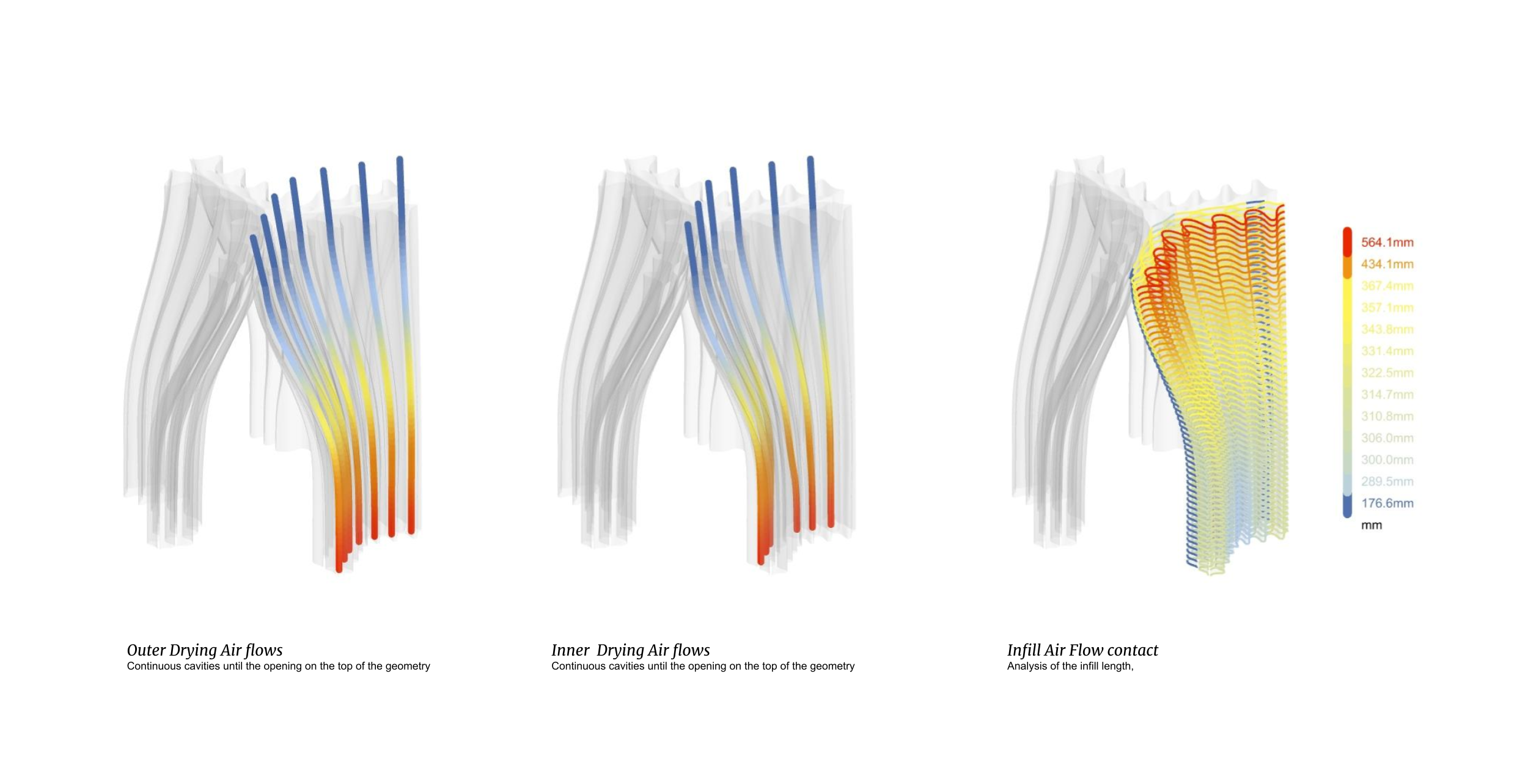
The solution of achieving the top while shifting the infill and maintaining the same infill geometry section on every sliced layer, allowed us to obtain cavities that have a continuous airflow allowing proper ventilation, in the same time with speeding up the drying process.
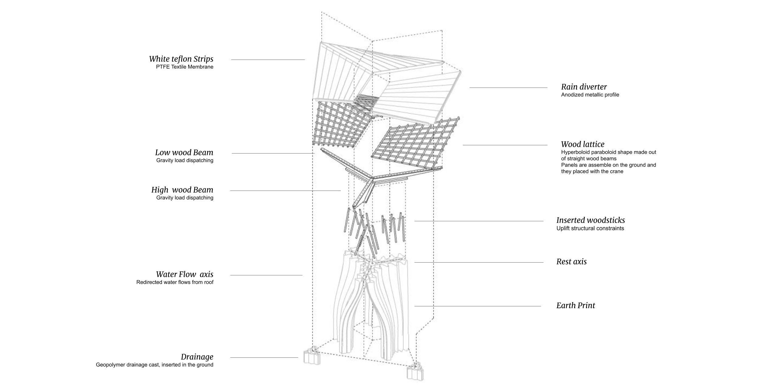
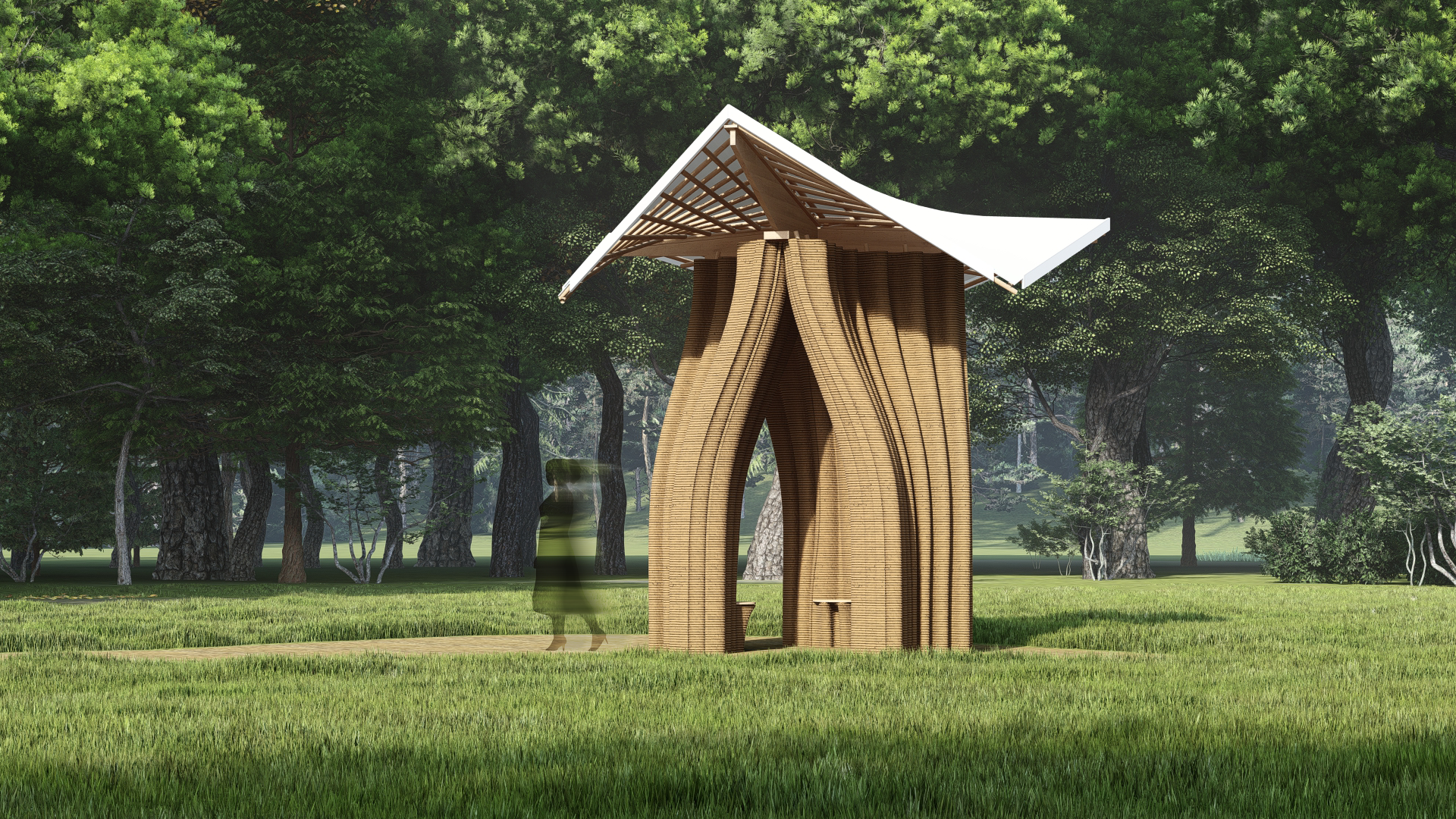
The cover
The roof consists of three hyperboloid paraboloid panels, geometry is chosen for water and wind redirecting, trajectories visible in the below analyses.
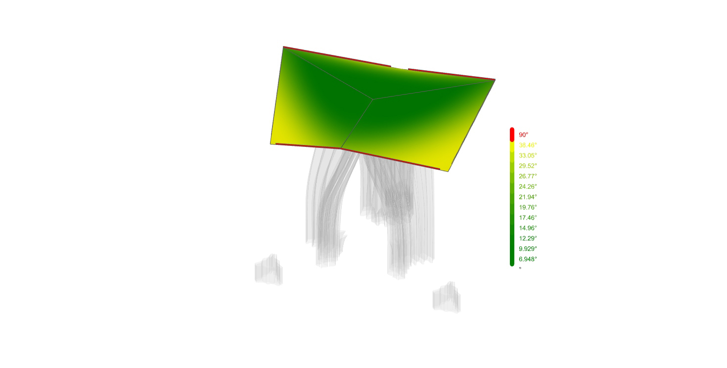
For gravity load dispatch, the structure of the roof consists in a support wooden-beam that lays in direct contact with the clay to disperse the forces. However, the uplift forces needed to considered as well, even though the potential of the geometry is redirecting the winds, therefore, the attachment on the printed object was solved by wooden-sticks interlocking the beam.