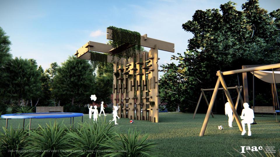
How can we use irregular elements of reclaimed offcut-timber to challenge the methodology of using planar, Interlocking and stacking techniques which can then be utilized in the design of forms ?
Data Collection
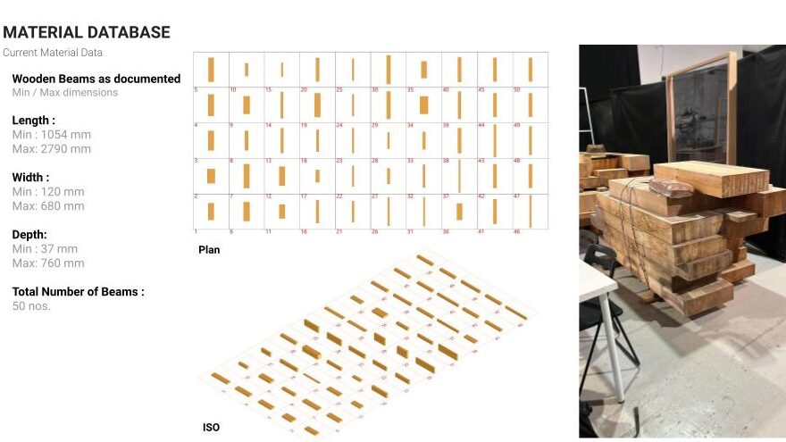
This first starts with a collection of materials and the creation of a database. This database serves as a resource for the planning and creation of modules that serve as the building blocks for the structure. Logging dimensions is a crucial step in ensuring each piece will be used to its fullest.
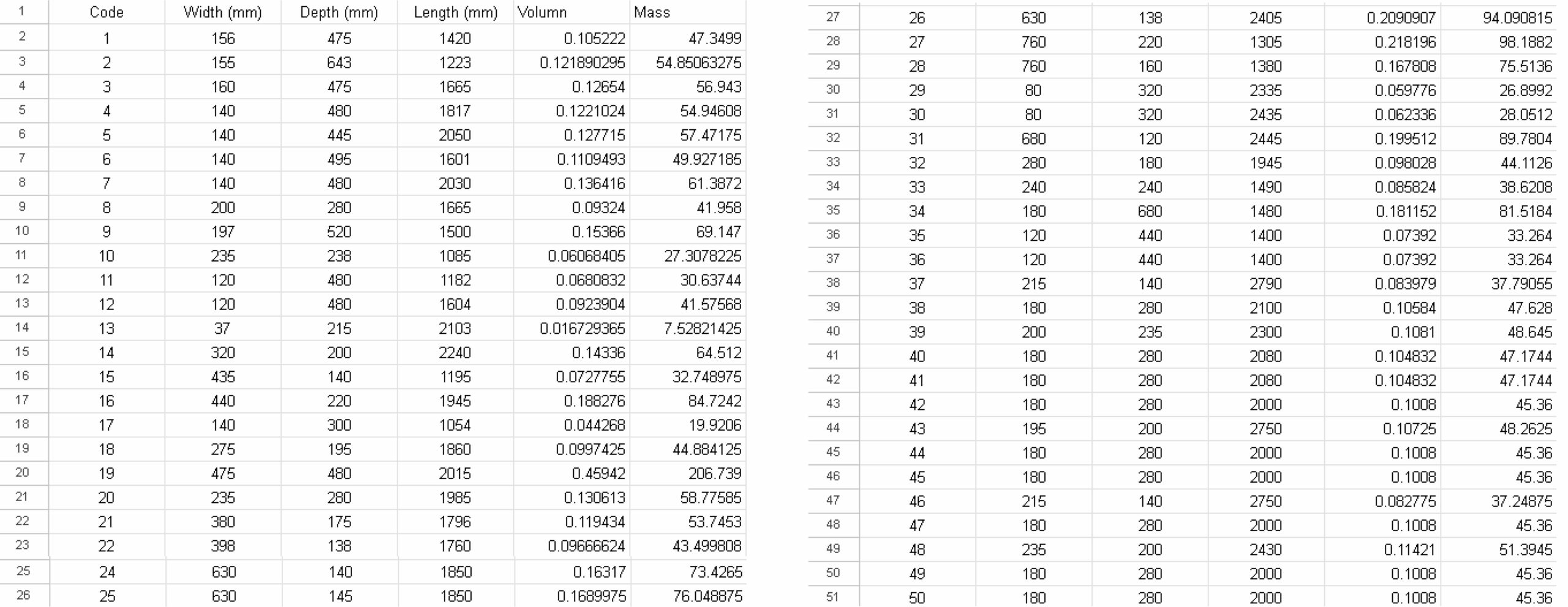

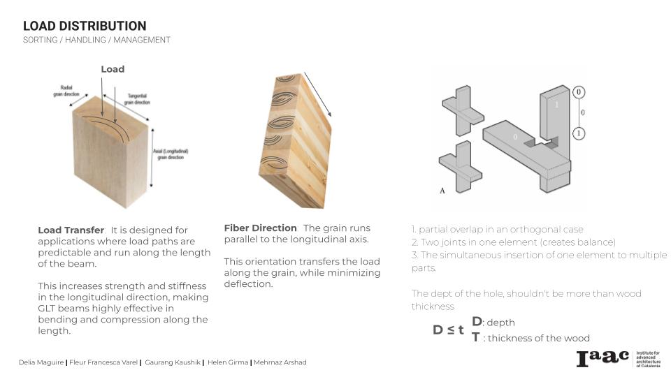
Through the collection of pieces, a range of dimensions was set. The pieces were then looked at in terms of timber fibers and type of wood. GLT is a type of structural engineered wood product constituted by layers of dimensional lumber bonded together with durable, moisture-resistant structural adhesives. It is strong and durable.
The idea for the creation of modular pieces includes slicing the GLT Beams into thin 3.5cm sheets. This creates a specified dimension which is needed for the pieces to fit together with the type of joinery. These sheets were then put into a secondary database that can then be used to select the specific beam that will be used in the construction.
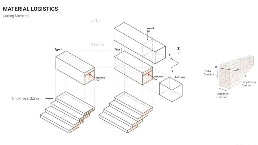
Cutting in the longitudinal direction, with a thickness of 3.5cm.
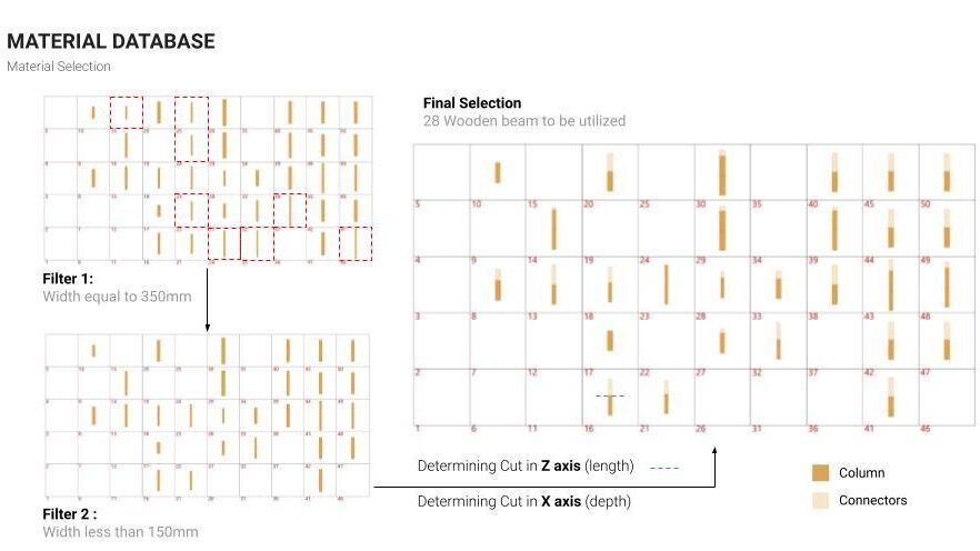
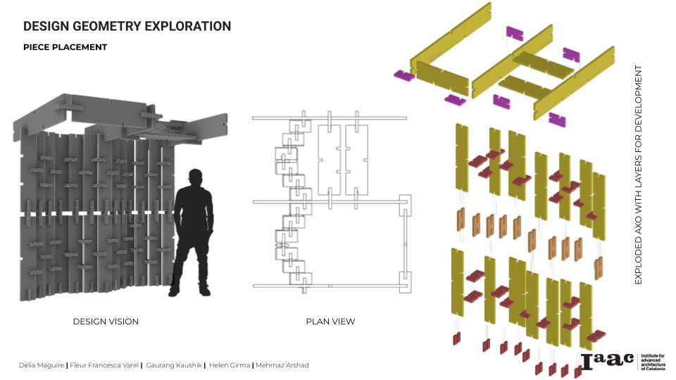
Pieces were then chosen based upon dimensions needed. An “X” axis dimension was then established and cut lines were added to the selection. Two types of pieces are cut with this range, a column piece, which acts as the main beam, and connector pieces, which act as supports to join the columns.
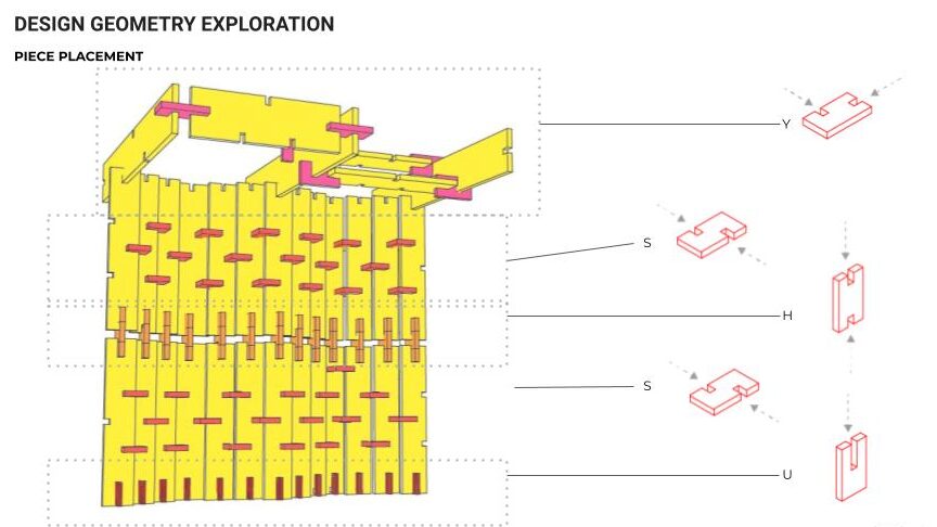
The geometry of the connectors and the columns follow a half and thirds logic. This allows for the pieces to fit together in different directions and configurations. One column geometry allows for “Y” and “X” growth. The connectors allow for growth in three directions.
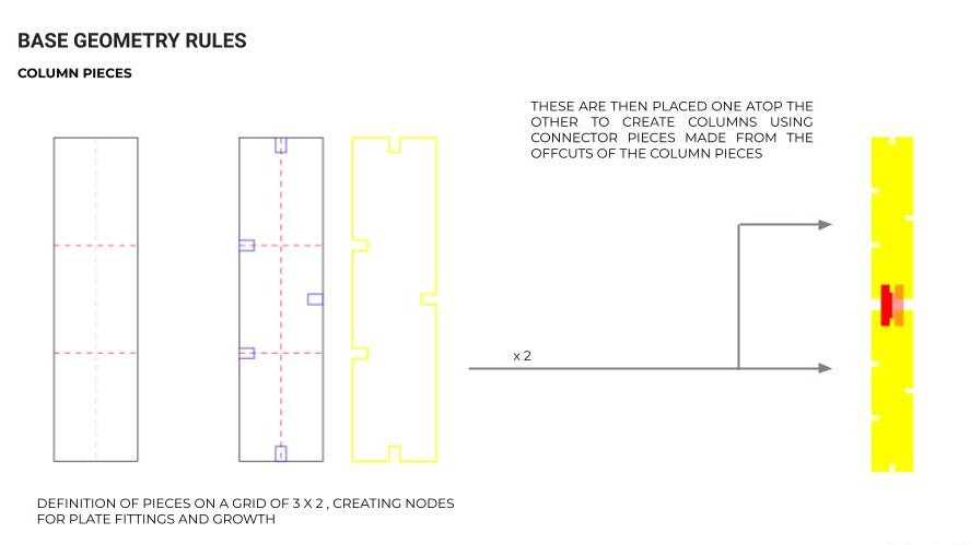
Column Geometry.
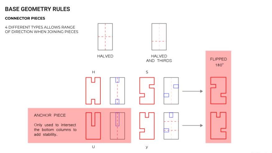
Connector Geometry.
Four pieces created from different cuts based upon dimensions of connector piece. An “H”, allows for vertical growth, “S” gives horizontal growth in either the forwards or backwards direction based upon the rotation of the piece. A “Y” connector shifts the direction in a perpendicular direction. And an “U” connector allows for stability of the upright column pieces.
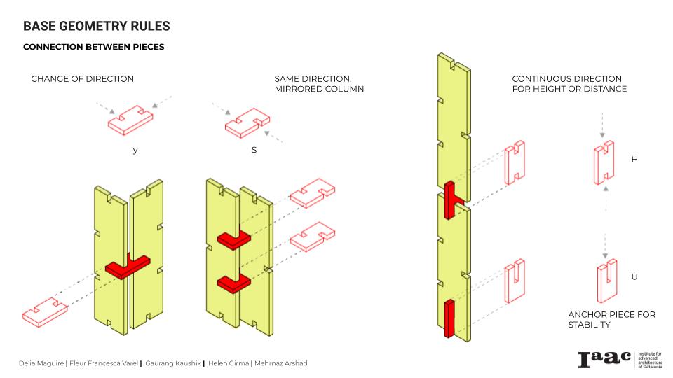
This logic can then be applied for designing. In this case a pavilion style design was created.
The creation of these geometries that can then be attached together to create larger architectural designs needs to be done in tandem with robotic fabrication. This allows a larger variety of angles to be explored than can be done with a standard manual machine. The 6 Axis robotic arm is much more equipped to be able to precisely cut at these specific angles, and the grabber end-effector is stronger and less dangerous to use to get the wood beams near the saw to cut. In this way, rotation and spatial placement when cutting the geometries is also able to be explored.
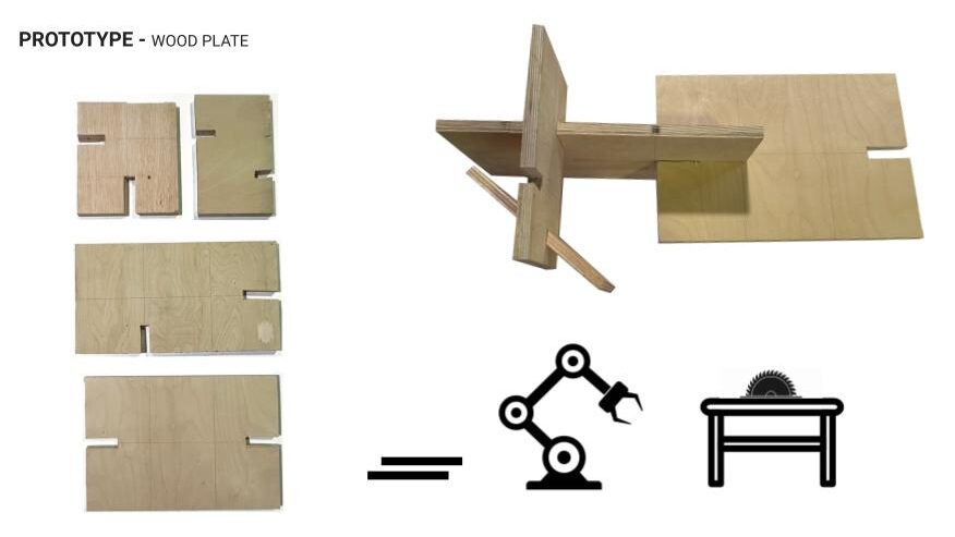
Keeping the rules of the geometries explained above, a wider variety of interlocking angles can start to be explored when using robotic fabrication. The process is simpler and less dangerous than manual construction.
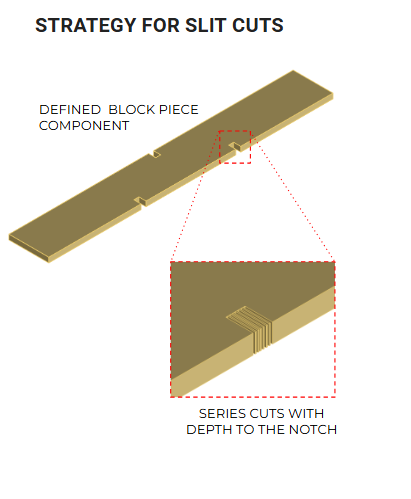
This is done through a series of notches that can be cut at one time with the robotic arm. This ensures that the blade cuts evenly on both sides of the piece and the smaller section of the cut can be taken out.
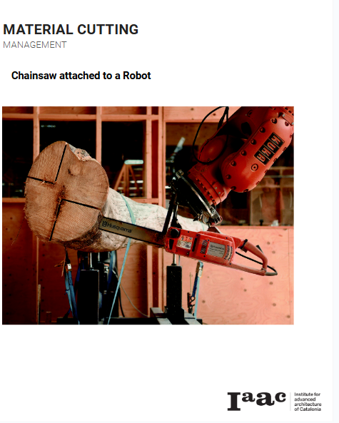
In terms of cutting the original material stock which in this case have come has large beams, another robotic fabrication approach was proposed. Since the amount of heavy machinery needed is not found in a standard woodshop, a chainsaw will be needed to slice the beams into workable planks. This takes into account the size of the beams and their fiber direction. Since the beams came as GLT, they are strong enough to be cut thinly, into 3.5cm planks.
Taking into account the direction of the wood fibers, cutting longitudinally can be a challenge for a manual chainsaw, as cutting the beams straight though and acquiring clean, parallel cuts can pose a challenge. However, mounting the chainsaw to the robotic arm, as seen in other case studies, can prove effective for achieving straight, parallel cuts. The tolerance of the chainsaw is wider, however, and so in the code we need to take into account a 1cm cut line for the blade.
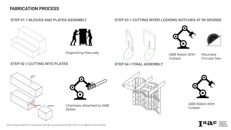
In all, the fabrication process needs to be parallel with robotic fabrication techniques to quickly, safely, and more effectively position and cut pieces for planking and creating intricate geometries. These geometries can then be catalogued and used in a wide variety of designs.
