Overview: Rhino.Inside as a Revit Workflow
Integrating the flexibility of designing Grasshopper into the enclosed and precise environment of Revit is an extremely powerful workflow.
Main Aspects
- Enhanced design capabilities: Combines the freeform modeling capabilities of Rhino with the BIM (Building Information Modeling) functionality of Revit, allowing for more complex and innovative designs.
- Streamlined workflow: Facilitates seamless communication between the two platforms, reducing the need for file conversions and improving overall efficiency.
- Parametric design: Integrates with Grasshopper, enabling users to create and manipulate parametric models in Revit.
- Improved collaboration: Facilitates better collaboration between team members who use different software, as it allows for easier exchange of design information.
- Customization: Offers the ability to create custom scripts and plugins to extend the functionality of both software programs.
Challenges
- Learning curve: Users need to be proficient in both Rhino and Revit, which can be challenging for beginners.
- Performance issues: Complex models with large amounts of data can cause performance issues or crashes, impacting productivity.
- Compatibility: Some features or elements may not translate perfectly between Rhino and Revit, potentially leading to discrepancies in the final design.
- Licensing costs: Users must have licenses for both Rhino and Revit, which can be expensive, especially for small firms or freelance professionals.
Workflow Description
Concept
The project is located on Mars and as for the nature of the location the project is very unconventional. The purpose of our group was to develop recreational function for the first established crew for the duration of one year. The main challenge was to tackle the psychological challenge of monotonous spaces. For that reason we decided to break the pattern and create a form that, because of it’s configuration it will allow for different interactions ( walking, jumping or climbing) providing the exercise and fun typical of a playground. The design ideas followed the workflow development strategy and for every concept we updated and enhanced the translation of the design into Revit for its documentation.
Evolution and Process
The design process started with analyzing the three-dimensional space requirements of various recreational activities. This analysis was used to create informants for the overall shape and guide the design. The design team then investigated how these spaces could interact and overlap to create a more efficient use of space.
Next, the team looked at the construction technology. They started by considering the space constraints of a rocket ship and then looked at the assembly price of a folding structure. The internal environment was pressurized, and the outer regular layer was 3D printed to create the external shell.
Phase I: The Starpod 1.0
The initial phase was the key guidance to set the following steps of the Rhino to Revit workflow. Although the final shape is very different this initial step was useful to set the ground of the logic we will deploy to transfer the geometry and the data from one software to the other.
Phase II: Playground Pods 2.0
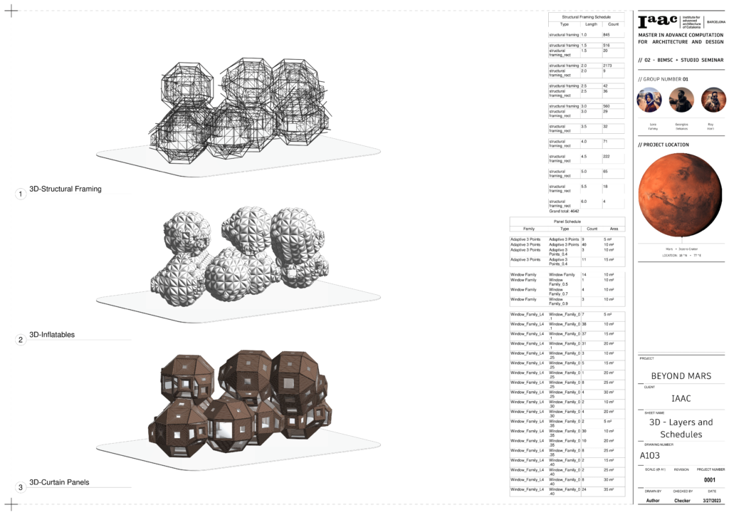
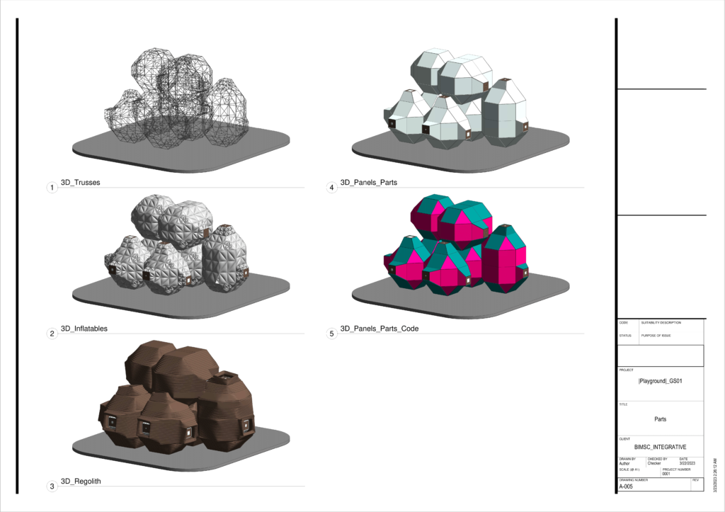
Modules were aggregated for the colony by the design team, considering environmental factors and the master plan framework in strict logic. Investigations were made on how the colony could be phased and module growth could accommodate a larger population. Rhino.Inside is used to translate parametric topology into structural framing elements, generic models, and adaptive components. The shape was refined and simplified for the complex recreational program by the team. An axonometric view was created to understand individual components of the structure comprehensively.
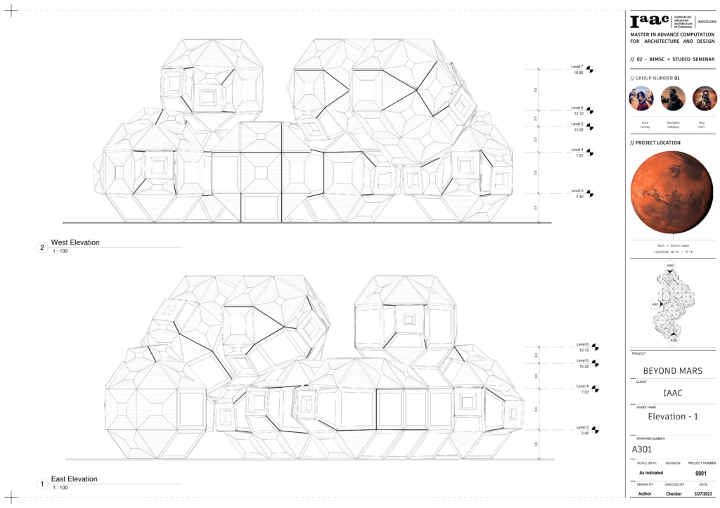
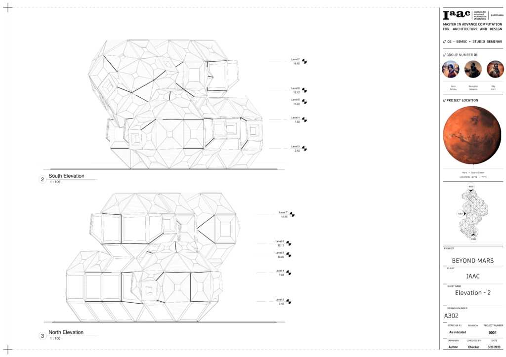
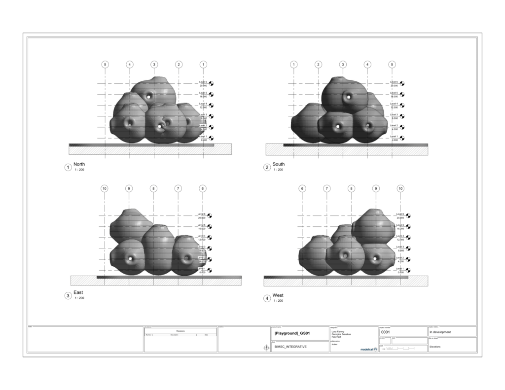
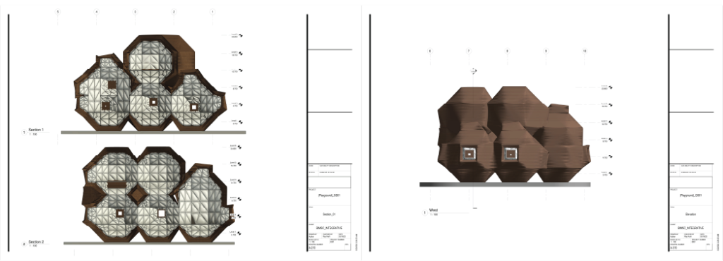
The showcasing of the layering of a pod structure from a 3D printed regular exterior to the interior inflatable cushions was carried out by the team. The trusses that connect the panels and inflation were distinguishable. A gradient color sheet was created by the team to filter the 3D printed regular layers based on the duration of their print, one per week. A more detailed view of the four elevations was presented.
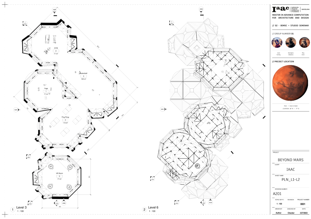
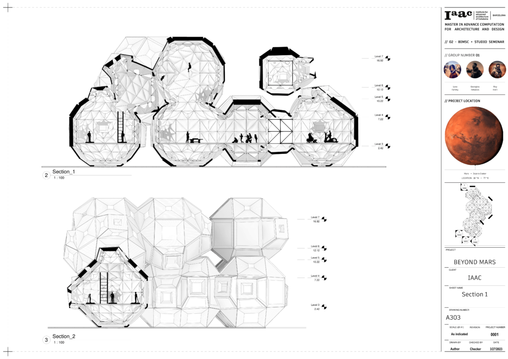
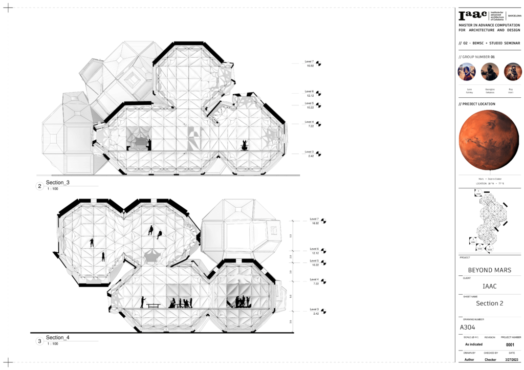
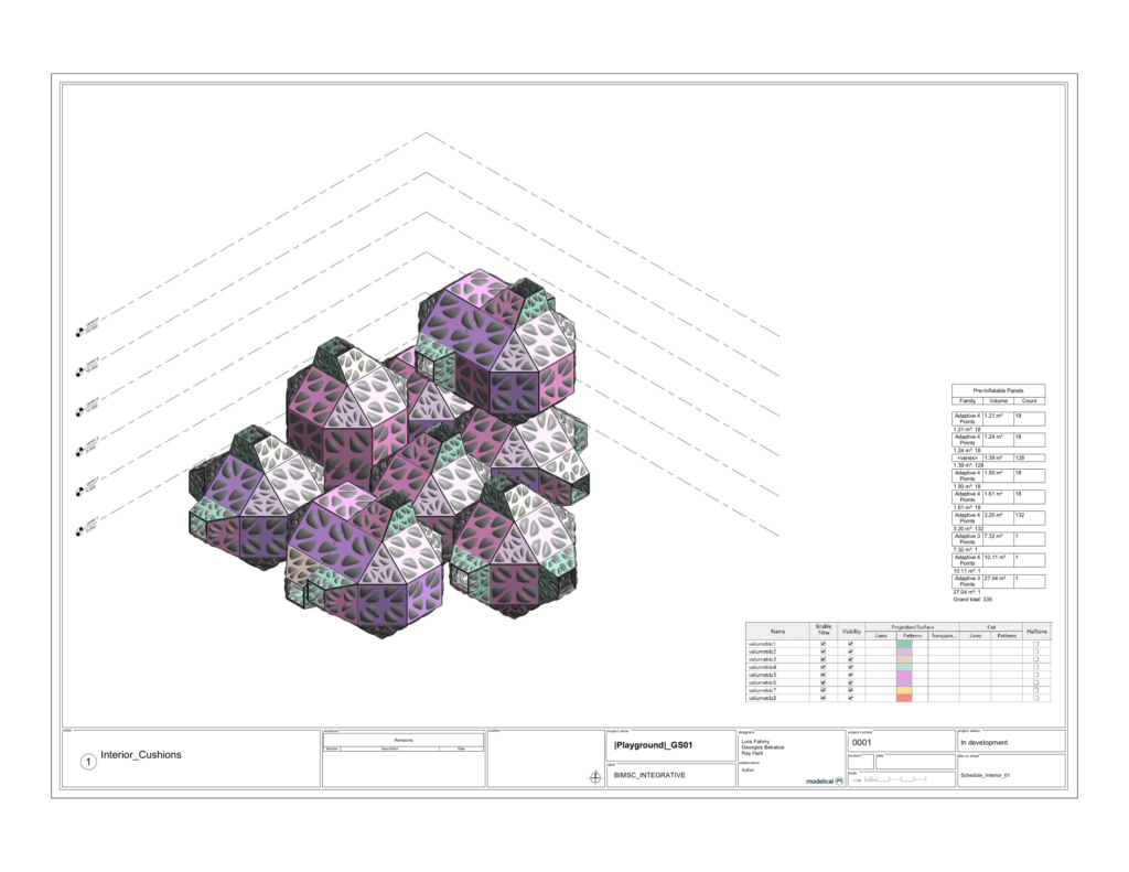
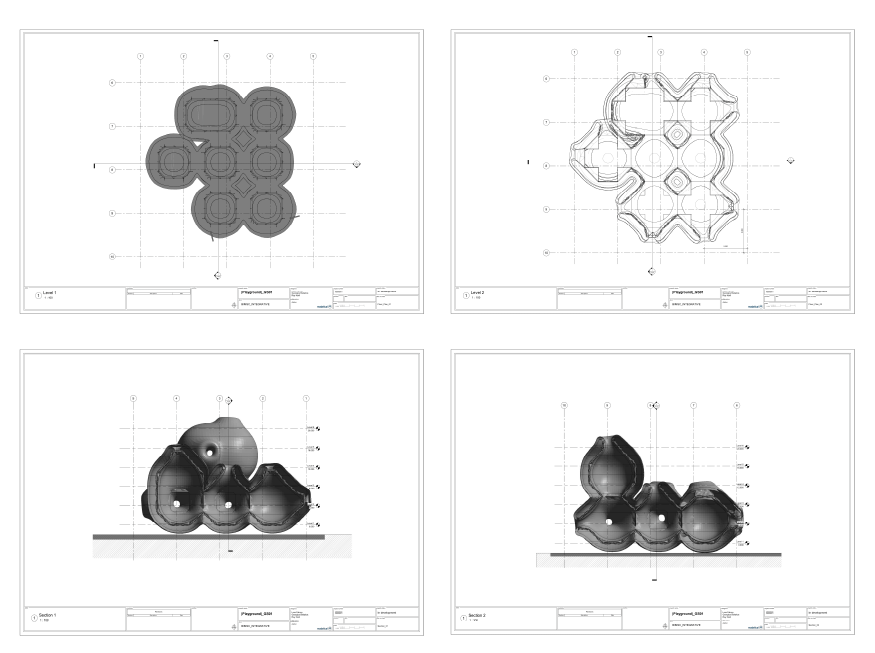
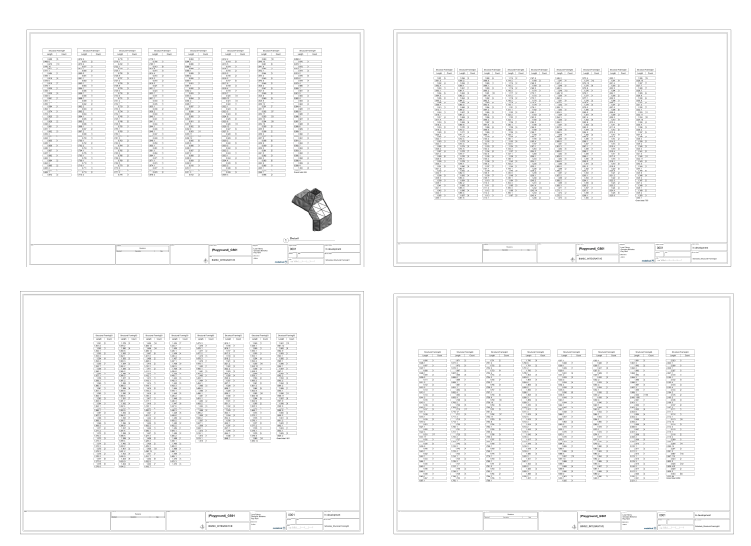
The utilization of the web hook through Speckle to panelize the walls within Revit directly from Rhino.Inside was done by the team. Another approach was explored by using Dynamo and utilizing wall by face, which yielded similar results. The panels were filtered based on their volume and adaptive component number, with each group distinguished by color rather than gradient. Typical horizontal and longitudinal sections were included, along with a comprehensive catalog of the structural trusses indicating their count and length.
Phase III: Playground Pods 3.0
Some abnormalities in the layering and connections were highlighted, and an analysis was provided on how the structure was elevated and refined. The team kept working on improvements and details, starting from structural frames that would be the structural support of a foldable system.
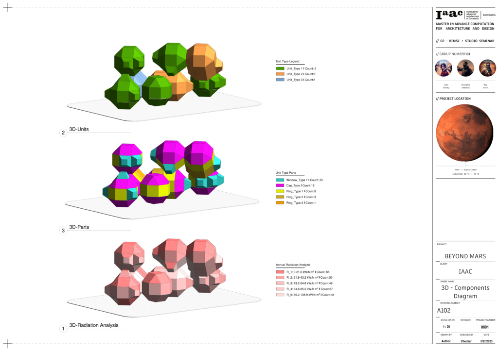
The panels were divided by colors to indicate the foldable parts that would be shipped from earth. Each panel had its own ID and could be combined on-site by astronauts in different ways. The inflatable stage was also displayed, with customizable windows in orientation, inclination, and degree of opening. Finally, the 3D regulate printed and divided into timeline layers were shown.
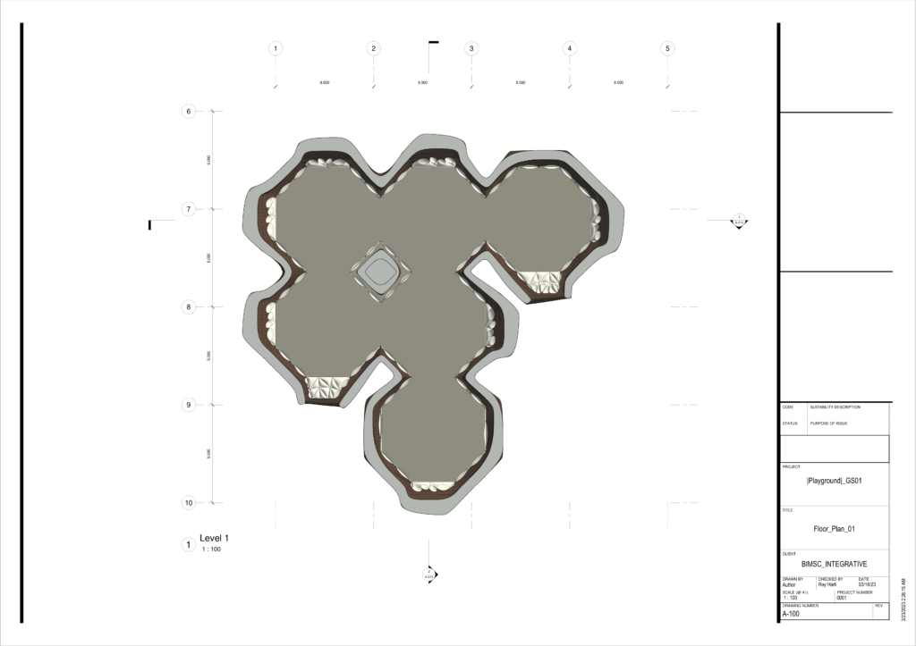
Designing recreational space for a colony on Mars is a challenging task that requires a thorough understanding of various factors such as space requirements, construction technology, environmental factors, and the master plan framework. This design process provided a comprehensive understanding of the details in order to proceed with the final documentation.
Process Renders

Final Documentation
Phase IV: Playground Pods 4.0
Finalized for Studio.
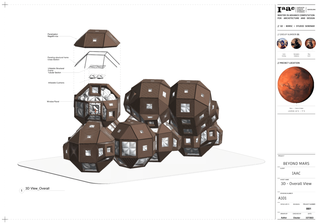
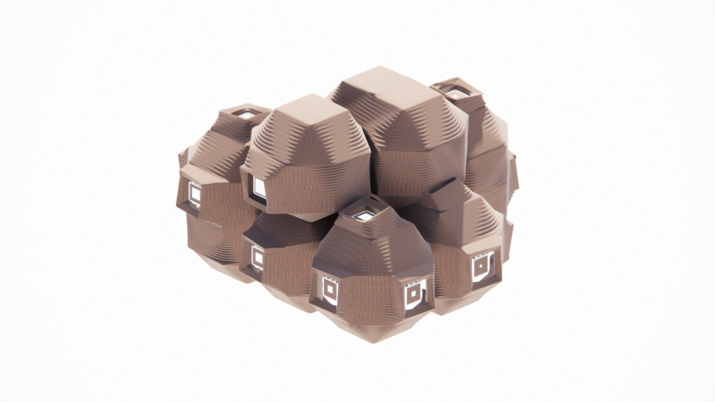
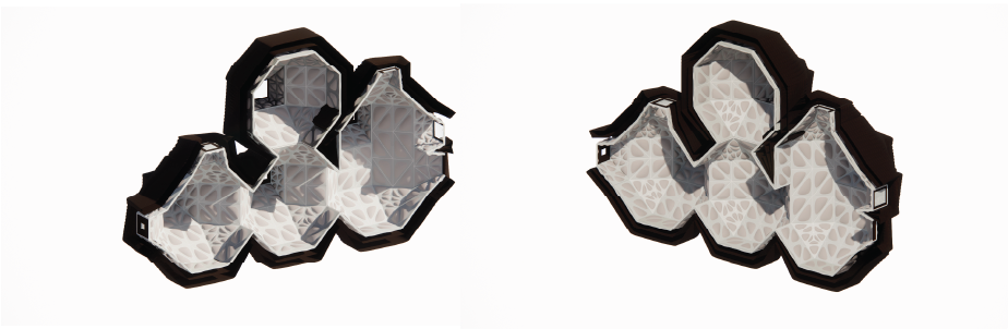
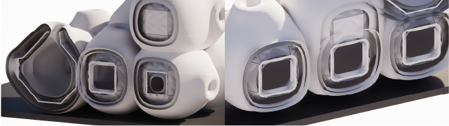
In this final workflow process all the collected workflow up to this point are utilized to get to the final configuration. The main difference of this final configuration consists in the technology deployed for the final 3D printed layer. The aggregation configuration would have made it difficult to 3D print the layers over the inflatable structure, for that reason and order to achieve the maximum utilization of the material the 3D printed regolith layer to protect from radiation is replaced with 3D printed panels that have a framing structure to hold it over the inflated structure. In addition to allow some amount of lighting through the windows and the inflatable semitransparent plastic there is a hole sealed with ice.
The parts are classified in bigger units components and modular components. The parametric approach guided the thickness and the opening of the panels. As you can see from the diagrams a solar radiation analysis is linked to the parameters of the windows and panels families to control thickness, windows’ orientation and degree of opening.