Neuron is a project developed during the IAAC MRAC 3.1 Welding Workshop that explores human–robot collaboration in the assembly of space-frame structures. The project focuses on the interaction between a Universal Robots UR10e robotic arm and a human welder, working together to assemble pre-cut steel bars through a continuous exchange between robotic precision and human judgment.
Conducted under the guidance of Nacho Monereo, Prottay Roy Chowdhury, and guest artist María Mallo, the workshop investigated what happens when human participation is not treated as a safety constraint but as an essential part of the fabrication logic. By positioning the human and the robot as active collaborators, Neuron examines new possibilities for assembling complex spatial structures through shared agency and coordination.

The project began with a simple question: how can human in the loop participation become an essential part of robotic fabrication rather than just supervision? We set out to design a workflow where the system cannot function without continuous input from both the human and the robot. Inspired by the way neurons communicate in the human body, Neuron treats collaboration as a network of signals exchanged between two agents. A Universal Robots UR10e robotic arm and a human welder act as two interconnected nodes, communicating through interfaces such as the HTC Vive Controller, MediaPipe, and a Web dashboard. Just like neurons exchanging signals across synapses, the system only operates when both sides continuously contribute to the process.
NNEGOTIATION THE GEOMETRY : LOOP RULES
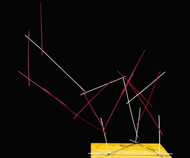
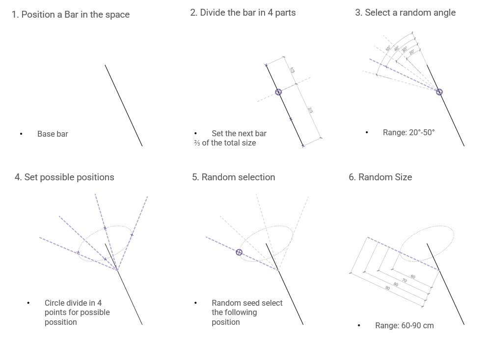
The process begins by positioning a single “Base bar” in 3D space. This initial member is then divided into four segments, with a specific connection point strategically set at 2/3 of the total size to define the hierarchy for the next member. To introduce the first layer of controlled variability, the algorithm selects a random angle from a predefined range of 20° – 50°.
To further the spatial complexity, the system establishes potential rotation planes by dividing a circle into four discrete points, marking the “possible positions” for the next branch. Using a random seed, the algorithm then selects one of these four positions to place the subsequent bar. Finally, the length of the newly generated member is randomised within a range of 60 – 90 cm. This stochastic approach ensures that the resulting structure emerges as a differentiated organic form rather than a repetitive grid, allowing for a unique structural evolution in every iteration.
NEGOTIATION THE GEOMETRY : MANUAL RULES
While computational logic provides the blueprint for growth, the physical realization of these complex forms requires a clear set of “Manual Rules” to bridge generative design with tactile construction.
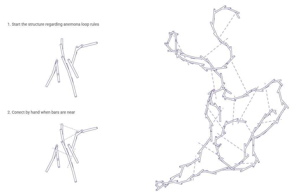
The transition from digital simulation to physical construction is managed through a two-step assembly protocol defined by specific manual rules. First, the structure is initiated according to “anemona loop” rules, which establish the primary recursive logic for the branching geometry. Once this framework is in place, a secondary rule is applied to connect bars by hand whenever they are in close proximity. This hybrid method ensures the assembly maintains its algorithmic integrity while achieving structural stability through manual reinforcements, effectively turning independent branches into a singular, interconnected web.
STATE MACHINE : THE LOGIC OF THE WORK LOOP
The integration of human intuition and robotic precision is governed by a structured state machine that defines a cyclic workflow known as “the logic of the loop”. This process begins when a human operator uses a Vive controller to record spatial data, which prompts the computer to generate a random anchor point, angle, and length for the next structural component. Once these parameters are approved via a dashboard, a human operator selects a bar from pre-cut stock ranging from 60 to 90 cm and loads it into the system. The robot then executes a pick and place operation to move the bar to the target, provided the system detects no collisions. If a collision is identified, the operator adjusts the workspace to trigger a recalculation; otherwise, the robot holds the bar in position for the human to perform the final weld and confirm the connection, allowing the entire loop to restart for the next iteration.

SYSTEM ARCHITECTURE : Robot – Human Interaction
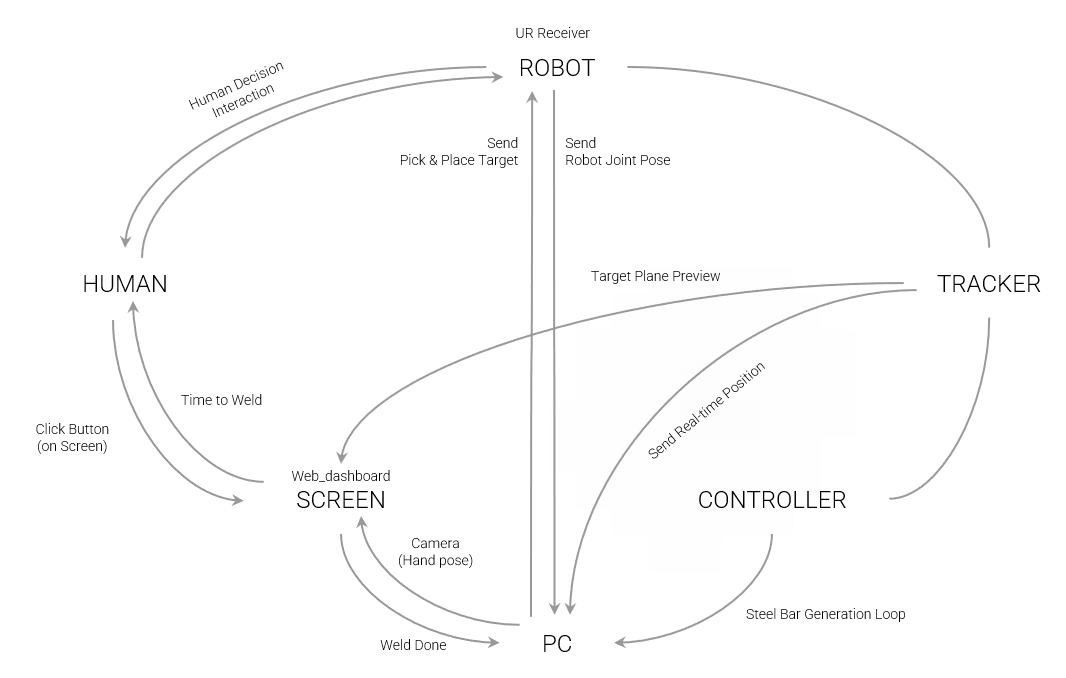
The technical architecture of this project relies on a highly synchronized communication network that bridges the gap between digital simulation and manual assembly. At the heart of the operation, the PC acts as the primary coordinator for all data streams by managing the steel bar generation loop and calculating the geometry for each new element. It maintains robotic accuracy by sending pick and place targets to the robot receiver and monitoring robot joint poses, while simultaneously receiving real-time positioning data from the tracker and controller to align the digital model with the physical world. This complex data is translated for the operator via a web dashboard on a screen, which provides a target plane preview and integrates a camera to track hand poses. The final stage of the assembly cycle depends on human decision interaction, where the system signals the appropriate time to weld. Once the operator performs the physical connection and confirms the weld is done through the interface, the PC restarts the generation loop to create a seamless and iterative cycle of human-robot collaboration.
GEOMETRY GENERATION LOOP : LIVE LOOP PROCESS
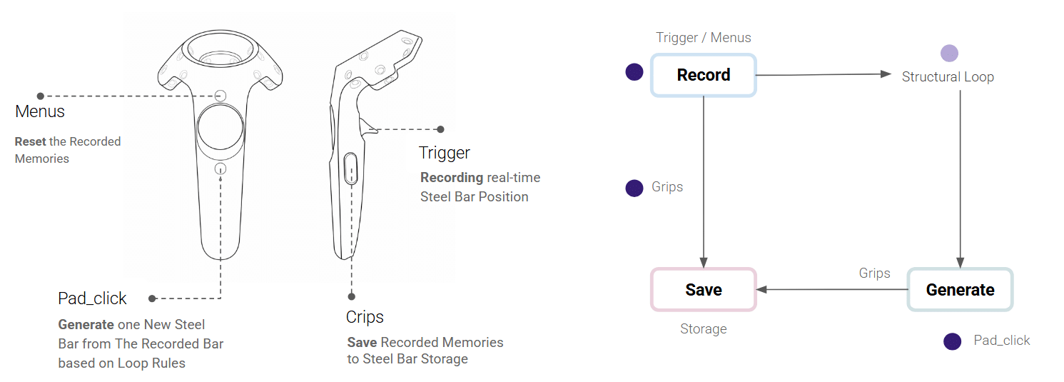
The hardware interface for this generative workflow utilizes a handheld controller to map physical actions directly to digital structural logic. The trigger is used for recording real-time steel bar positions, while the menus button allows the operator to reset recorded memories. By using the pad click, the user initiates the structural loop to generate a new steel bar based on the recorded data and established rules. Finally, the grips facilitate the transition to storage, saving these recorded memories into the project database to ensure that complex computational growth is managed through simple, tactile interactions.
FABRICATION PROCESS
Laying The Ground Work
The fabrication process begins with the construction of the base and the precision cutting of individual members. Once the material is prepared, the foundation pieces are installed to establish the initial structural state. This setup serves as the primary anchor point, triggering the computational “logic of the loop” where the system coordinates between human input and robotic placement. By securing these baseline elements, the iterative assembly cycle is initiated, allowing the structure to grow through a series of recursive branching and manual reinforcement steps.
RECORDING BASE GEOMETRY POINTS
The initial points for the base geometry were captured using an HTC Vive controller, allowing for a direct translation of physical space into the digital environment. This spatial input establishes the primary anchor points, which the computational system then uses to generate the foundational geometry required to start the recursive assembly loop.
GENERATING GEOMETRY LOOP
After the initial anchor points were recorded using the HTC Vive controller, the computational system utilized this spatial data to generate the base geometry and establish the foundation for the structural loop. With the geometry defined, the system then generated specific robotic pathways and joint poses required for the pick-and-place operation. This automated trajectory generation ensured that the robot could precisely deliver each structural member to its target while avoiding collisions within the workspace.
SCREEN INTERFACE : WEB DASHBOARD
When a risk of collision appeared, the robot was moved to another location to ensure the steel bar could be placed more safely. To manage this adjustment, a web dashboard was structured to capture real-time table relocation data, which was then directly incorporated into the computation. This feedback loop allowed the system to recalculate the robotic pathway based on the new spatial coordinates, maintaining the accuracy of the assembly despite physical shifts in the workspace.
SUCCESSFUL ATTEMPTS
We initiated the project by precisely seating the steel bar within its target 3D spatial parameters. Once the system confirmed the alignment, the bar was ready for the human operator to step in and perform the weld. This collaborative workflow has proven to be remarkably efficient, already yielding a fair share of successful attempts and a seamless transition between automated placement and manual craftsmanship.
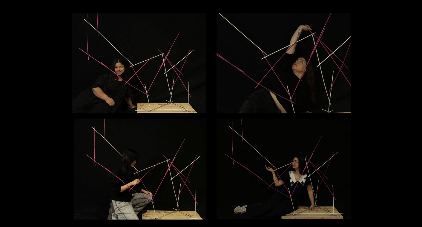
HUMAN – ROBOT COLLABORATION
On several occasions, the robot arms were manually calibrated to ensure they were placed in a suitable position before operation. This adjustment helped the arms reach the target point more safely and reduced the risk of collision during the process. In addition, the robot arms were sometimes positioned more precisely near the targeted point to improve accuracy, stability, and overall task performance.
MULTIPLE TRIALS
In some cases, the same target point was attempted multiple times to evaluate whether repeated positioning and welding improved the accuracy of the connection point. This was attempted because the previously welded structure was not completely rigid, which could lead to slight positional deviations during operation. Repeating the process helped achieve better alignment and improved the overall precision and stability of the final connection.
INADVERTENT ERRORS
Even though every effort was made to avoid collisions, they were sometimes unavoidable during the operation. In the event of a collision or potential contact, the collaborative robot was stopped manually by physically halting the robot arm to prevent further movement or damage. In critical and fragile situations like these, human–robot collaboration proved to be especially valuable, as human intervention allowed quick responses and safer handling of unexpected interactions.
WELDING
Lastly, the welding process was carried out. At this stage, the effectiveness of the human–robot collaboration became especially evident. The robot was responsible for holding the steel bar steadily at a precise position, while the human operator performed the welding of the joints. This cooperation combined the robot’s positioning accuracy and stability with the human’s flexibility, judgment, and welding skill, resulting in a more controlled and efficient workflow.
FINAL RESULT & DIGITAL TWIN