
State of the Art
Raw Timber and AEC Industry
Wood waste is often disregarded in the wood industry and the construction industry. Majority of wood used in construction is sawn and processed wood that not only generates waste on its production but it is also associated with high CO2 emissions, because of the embodied energy being released during processes like: harvesting, transportation, edging and trimming. Use of saw wood is being demanded nowadays due to the overstocking of forests, affordability and minimal processing regarding edging and trimming.
Several scanning methods have been deployed and tested in order to understand the irregularities of raw wood and its design applications in the construction industry. Methods like photogrammetry, gaussian splatting, LiDAR, depth cameras and computer vision are some of the methods that are being tested to understand structural properties of raw wood, direction of fibers and irregular morphology of the wood itself. Most of the state of the art projects that are working on understanding different aspects of raw timber have been utilizing scanning methods and generating computational databases on how to design and apply for architectural elements and design for the manufacturing process. This database is an output from the scanning process and it needs to be post processed in order to be cleaned, scaled and adjusted according to its needs.
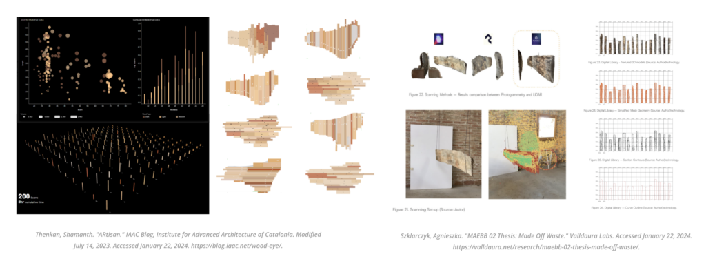
Figure 1 – Scanning raw wood Database References and its applicabilities
Figure 2 – Scanning raw wood for design for manufacture applicabilities
ROS and Design for Manufacture
ROS (Robot Operating System) is an open-source, flexible software framework for writing robot software. This system presents many advantages for robotic programming and development such as the interoperability within nodes and the integration with various sensors and actuators, it supports a vast range of robotic platforms which presents a flexibility for industries with different robotic systems, it is open sourced and provides real time process with adaptability for errors during robotic processes.
Most of the robotic process for design for manufacture are done offline and it presents an interoperability with Rhino and Grasshopper to link with the design and its alterations. Some plugins like COMPAS fab generate a ROS bridge link with the nodes that are being created in the ROS Noetic environment. However, there is still some real time feedback information to be improved and implemented for real time projects and parametric design.
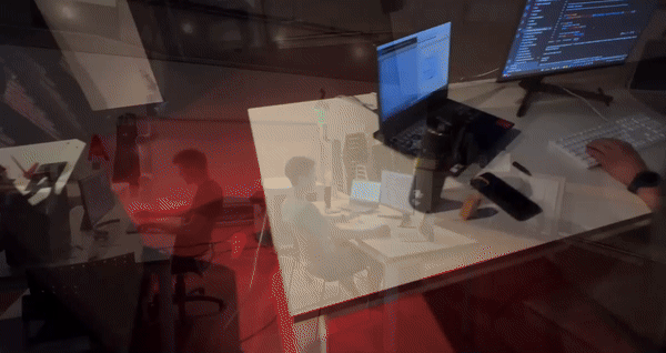
Figure 3 – “Branch Production.” RobArch 2024. Accessed January 22, 2024. https://robarch2024.org/Branch-Production.
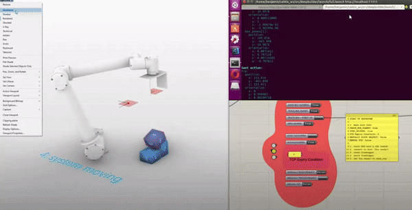
Figure 4 – “Block Stacking with ROS and Grasshopper.” YouTube video. Posted by “[Benjamim F],” June 1 2019. Accessed January 22, 2024. https://www.youtube.com/watch?v=r9Mek16Tkvw.
Aim and Workflow
The absence of an industry standard for real-time scanning and a direct bridge to Rhino/Grasshopper with ROS (Robot Operating System) represents a significant gap in the architecture, engineering, and construction (AEC) industry. Real-time scanning, crucial for accurate, on-the-fly adjustments during construction or renovation projects, currently lacks a unified, efficient approach, especially one that seamlessly integrates with popular design and modeling tools like Rhino/Grasshopper. The integration of ROS, known for its flexibility and modularity in robotics, could revolutionize this scenario. By providing a standardized platform for real-time data acquisition and processing, ROS could enable more dynamic and responsive design processes. This integration would not only enhance the accuracy and efficiency of construction projects but also foster innovative design practices, allowing architects and engineers to incorporate complex, real-time data directly into their models. This current research is exploring the integration between these two realms.
The workflow diagram depicts a process that starts with a robotic scanning system, which includes a collaborative robot (the UR10e), lighting for visibility, and the Azure Kinect for depth sensing. This setup is controlled by a central unit and operates within a ROS Noetic environment, contained in a Docker container for ease of deployment. The scanning results in a .PLY file, representing a point cloud of the scanned area. This data is then post-processed to enhance the image, which could involve cleaning and aligning the data for better accuracy.
The real-time aspect of the process is managed through Rosbridge, which translates ROS messages into PointCloud messages that are compatible with other software tools. Following this, the data is fed into Rhino 7 equipped with Grasshopper, along with other specialized tools like COMPAS FAB, Volvox, and Tarsier for advanced modeling and fabrication planning. The result is then used to create or update a Sticks Database, which stores the design data for future construction or fabrication tasks. This workflow suggests a continuous loop of scanning, processing, and modeling that could be incredibly beneficial for dynamic design adjustments in the AEC industry, allowing for high adaptability and responsiveness to the physical environment during the construction process.
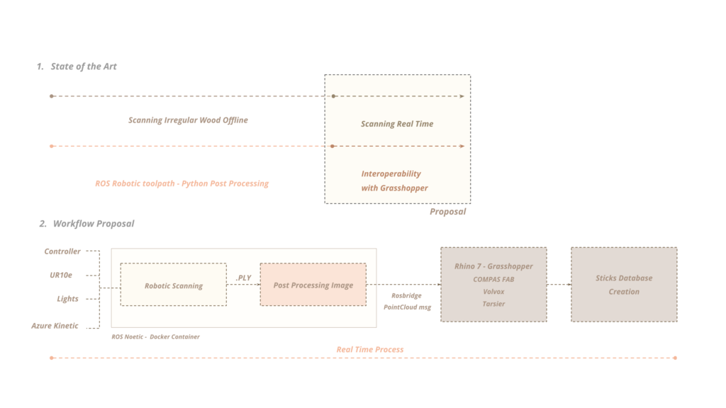
Figure 5 – Aim and Scanning workflow with ROS and Grasshopper
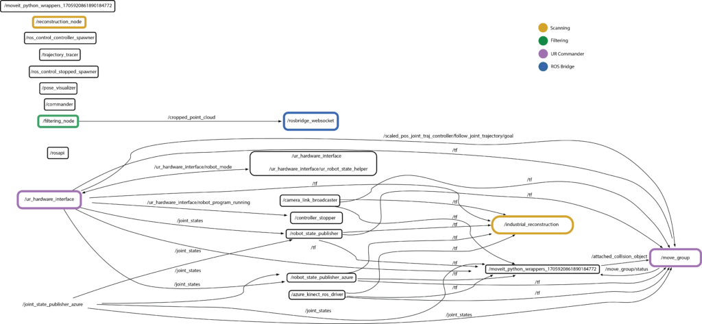
Figure 6 – rqt_graph of ROS Nodes and Topics during execution
Hardware and Software Setup
For this project, we chose to physically connect a UR10e robot and an Azure Kinect camera to an Ubuntu computer. This computer hosts ROS and our project repository, either within Docker or locally installed. Additionally, we have a second computer running Windows (in the same network), equipped with Rhino/Grasshopper and the COMPAS FAB plugin. Moreover, during testing, a team member used an Ubuntu virtual machine inside Windows (instead of the two-computer setup) to seamlessly test bidirectional communication and data transfer between ROS and Grasshopper.
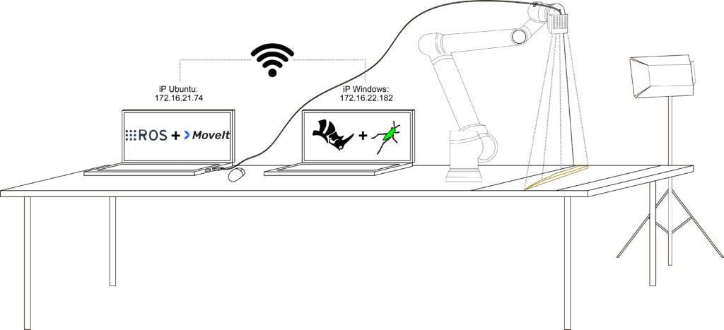
Figure 7 – Scanning Setup
Robotic Scanning Node
In the proposed workflow, the robotic arm follows a longitudinal toolpath set at angles of 45, 60, and 90 degrees, aligning with the wood grain direction to comprehensively capture the geometry of wooden sticks. This meticulous approach ensures that the Azure Kinect can achieve the best possible depth capture by scanning from multiple angles, which is crucial for accurately rendering the stick’s contours and intricacies. In response to the initial trials’ low quality, we adjusted the Kinect settings to WFOV and 15 fps (click here for more information about the Azure Kinect DK hardware specifications). Furthermore, we reduced both the voxel length and SDF truncation to enhance scan quality. To fine-tune precision, the robot operates deliberately at 0.02% speed and maintains a maximum height offset of 20 cm from the sticks. This approach enables a closer, more detailed capture without compromising overall scan quality.
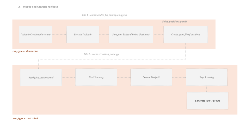
Figure 8 – Toolpath and Scanning Node pseudo-code
Post-Processing Node
Once the scanning node completes its operation and generates the raw .ply file, the post-processing node ensures the extraction of the object of interest while eliminating unwanted noise. Utilizing open3d, a bounding box is created to crop points outside its bounds, resulting in the point cloud of the desired object. This refined point cloud is then saved as a .ply file and published as a PointCloud message for use in subsequent processes. Looking ahead, we may explore configuring the Azure Kinect to limit its sensing range, essentially establishing a sensing bounding box to avoid unnecessary background scanning in the first place.
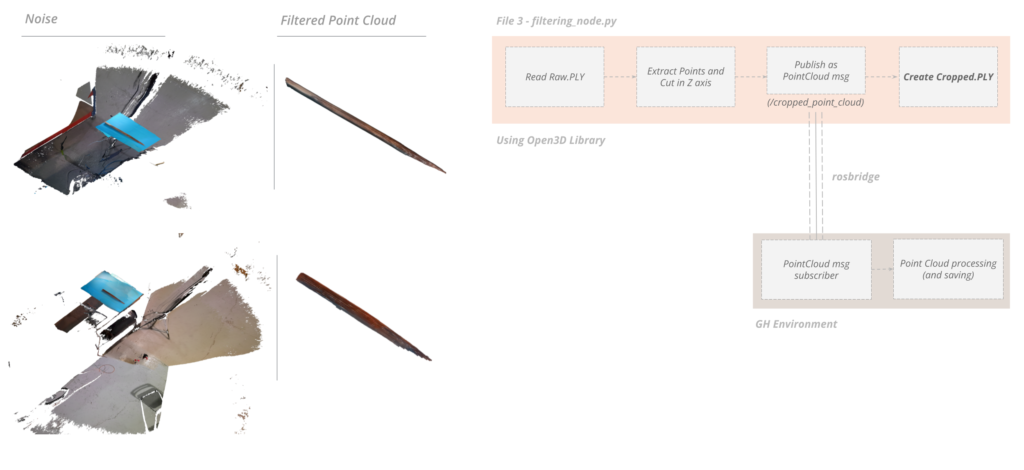
Figure 9 – Filtering Node pseudo-code
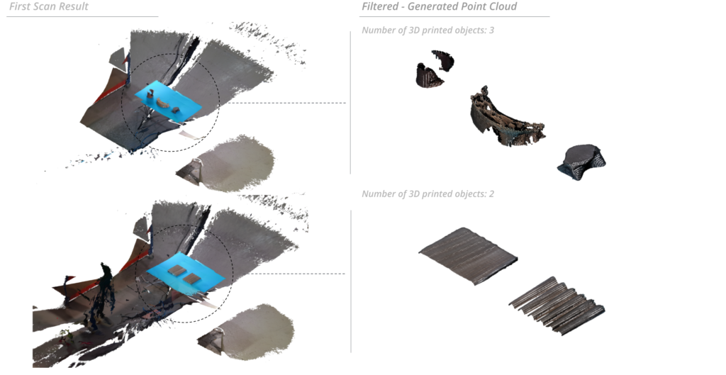
Figure 10 – Testing with different size and shape objects
Bridging to Rhino/Grasshopper
As mentioned before, the filtering node reliably publishes a PointCloud message every 10 seconds. Utilizing the COMPAS FAB plugin for Grasshopper, we seamlessly established a connection to ROS via an IP address (as detailed in the hardware setup section). We gathered data with x, y, z coordinates, and RGB color details for each point by subscribing into the right topic (/pointcloud). And using the Volvox plugin, we then pieced together the desired point cloud effectively. Looking ahead, our plan is to improve the Grasshopper file, enabling it to create a versatile database, accommodating formats like OBJ, STL, or any other suitable format for specific applications.
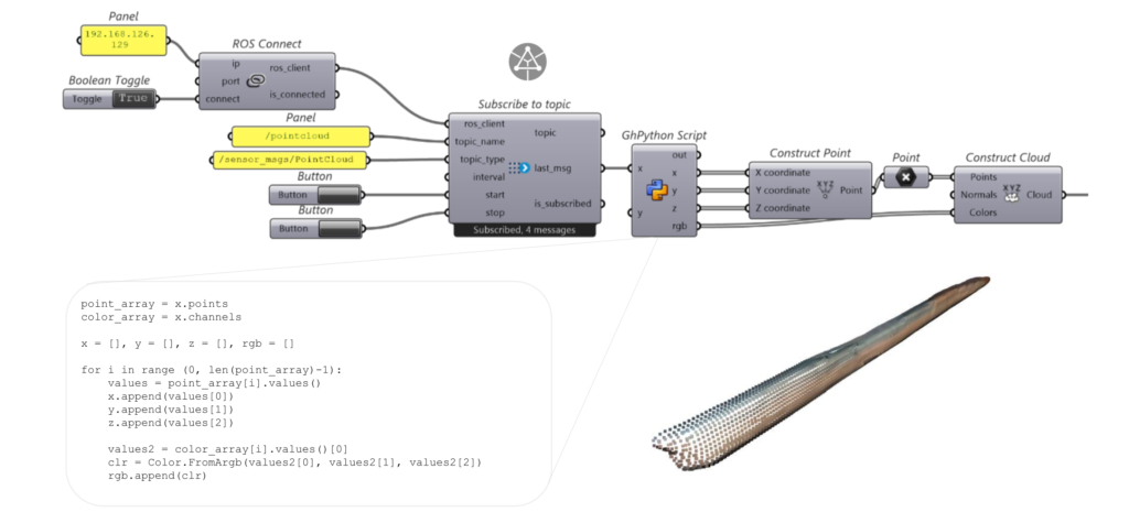
Figure 11 – COMPAS FAB plugin usage example with a point cloud
Conclusions and Further Steps
We have successfully completed the first part of the project by automatically extracting the desired object’s point cloud and sending it to Grasshopper. Nevertheless, there is always room for improvement:
Software
- Experimenting with various scanning techniques such as photogrammetry and Gaussian splatting to optimize object reconstruction.
- Comparative analysis of results between digital and physical models to evaluate accuracy and identify potential discrepancies.
- Utilizing Grasshopper for mesh database creation.
- Developing an automated scanning toolpath that adapts to different object sizes and shapes (as it can be seen in Fig.x the toolpath used for the stick scanning is not suitable for taller objects).
- Implementation of algorithms to extract grasping poses from scanned objects, enhancing robotic manipulation capabilities.
Hardware
- Upgrading to a more suitable camera for scanning small objects, such as the RealSense D435 and D435i.
- Integrating the gripper and camera into a unified tool, streamlining the scanning process and improving the overall efficiency of the system.
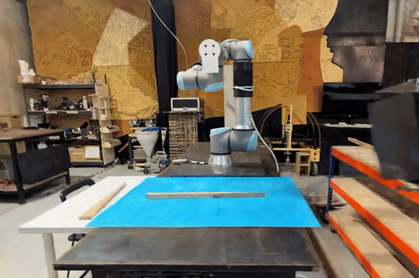
Figure 12 – Explorations about Gaussian Splatting
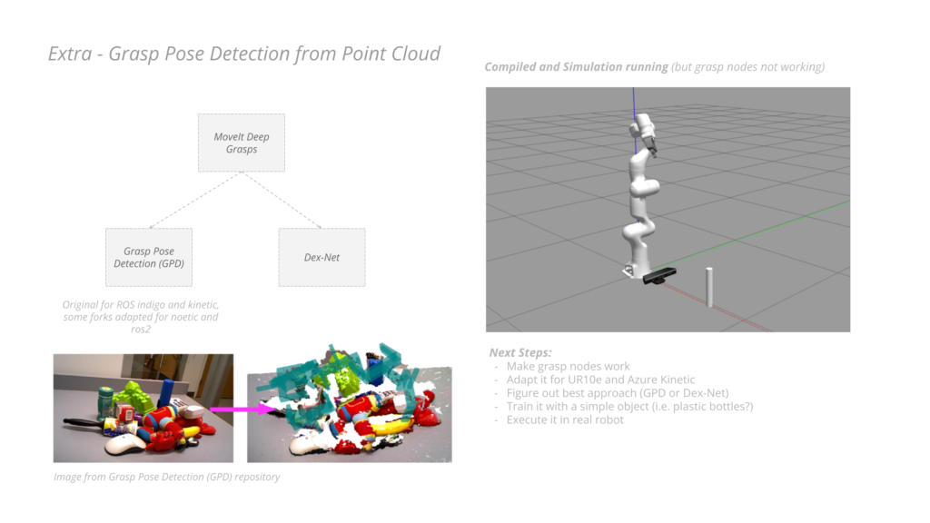
Figure 13 – Explorations about real time grasp pose detection
Figure 14 – Work Process
Github Link
You can follow the updates here: https://github.com/ainhoaarnaiz/software_II_project.git
