
Preliminary steps towards a hybrid workflow for smooth 3D printed surfaces.
Aim
To develop a hybrid workflow to obtain smooth surfaces on 3D printed clay for improved alignment and surface finish.
State of the Art
Additive manufacturing enables the precise and cost-effective creation of complex designs while minimizing waste.
One of the shortcomings common to additive manufacturing across all materials is that the surface finish is usually rough, as a result of the many layers of material that have been deposited. For this reason, post processing of additively manufactured parts has become a topic of great interest in the field of digital fabrication.
One solution is the use of hybrid manufacturing, where material is first deposited (additive), before later being removed (subtractive).
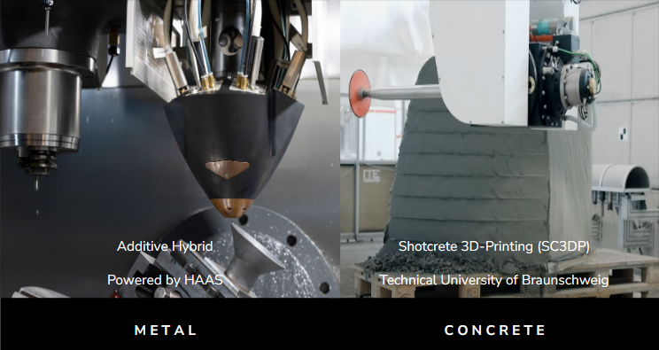
These hybrid approaches require less equipment and less material than traditional manufacturing, while still producing products of equivalent quality.
But what about our material, clay?
Clay is sustainable, long lasting, and sought after for its textures and familiarity and historical significance. Nowadays it is being explored extensively for its utility in 3D printing,
Yet we haven’t seen examples of these hybrid workflows for improving the surface finish of 3D printed clay parts.
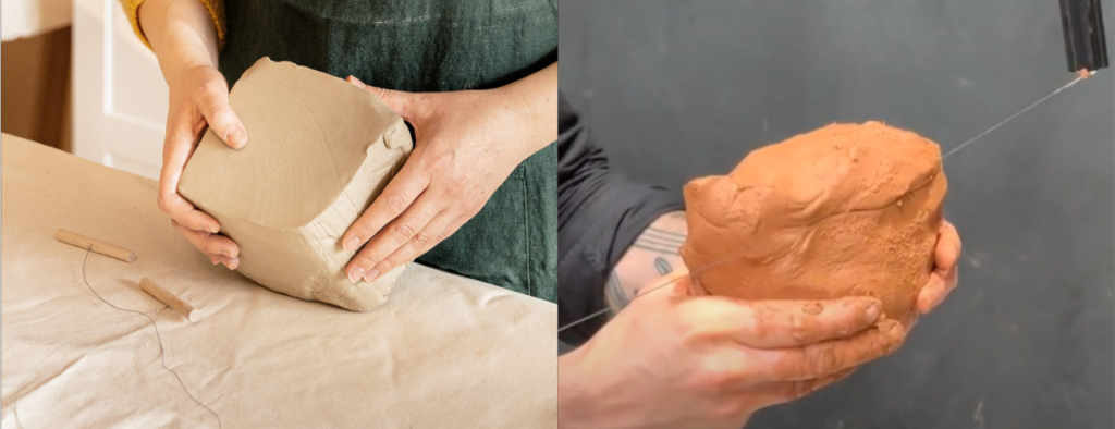
When we look at traditional craft with clay, we see that one of the techniques used is wirecutting, which offers a lot of opportunities for creativity, through unique textures and geometries.
https://www.iaacblog.com/programs/ithacut-wire-cutting-clay/
When we look at materializing with machines, we see existing parallels where wirecutting is used to very interesting effect.
Which leads us to the collision of traditional craft and digital fabrication, and becomes the stage for our project, whereby we apply a hybrid approach of robotic 3D printing and wirecutting.
Methodology
To accomplish our aim, we developed a workflow to use wirecutting, aided by 3D scanning.
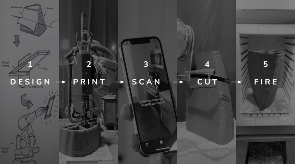
The process involves five steps. Each step will be described in detail, but it is important to note that not all designs can be 3D printed. There are a great deal of design considerations and constraints that arise from each step of the process.
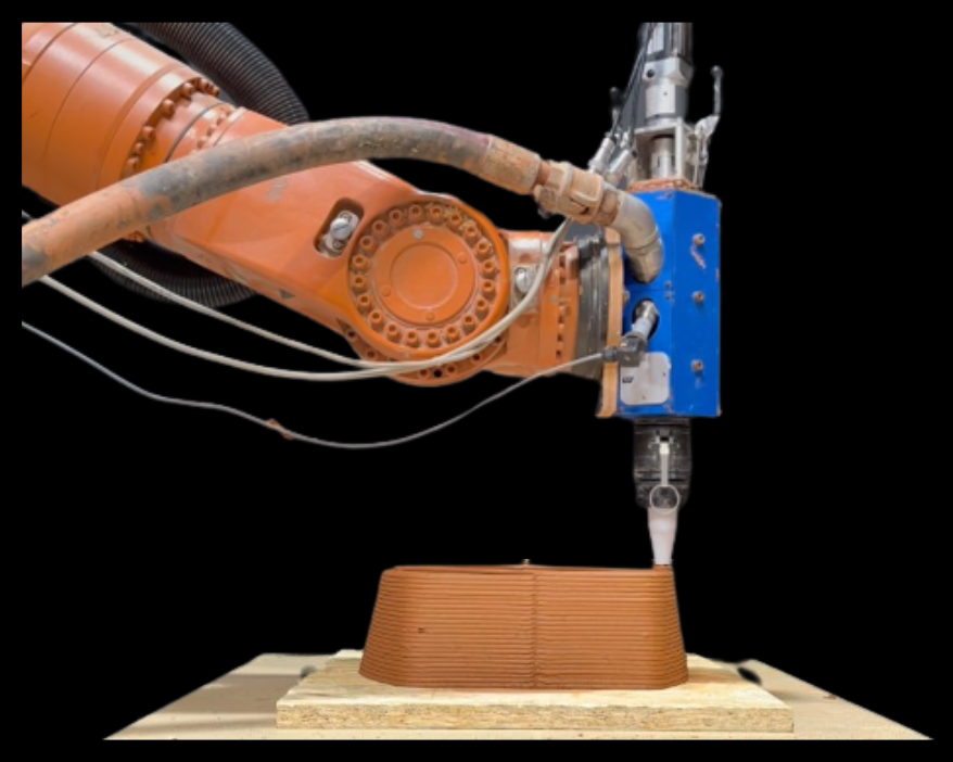
Printing
Our material was a simple mixture of clay and water, mixed to a moisture content of 25 and 27% depending on the scale of the object and the extruder and nozzle being used.
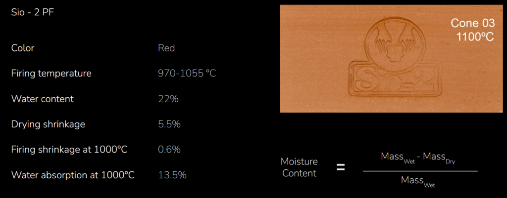
To ensure consistency we verified the moisture content through a process of weighing, baking until bone dry, and weighing again.
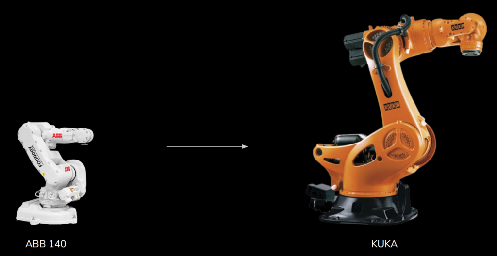
To print we use an extruder with a screw. We print at various scales using a both desktop cartesian printer and robots.
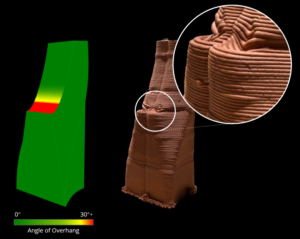
Overhang
The limitation in overhang angle is due to the soft material and the finite layer deposition process, with a recommended limit of less than 37 degrees. Horizontal layers cannot be printed unsupported
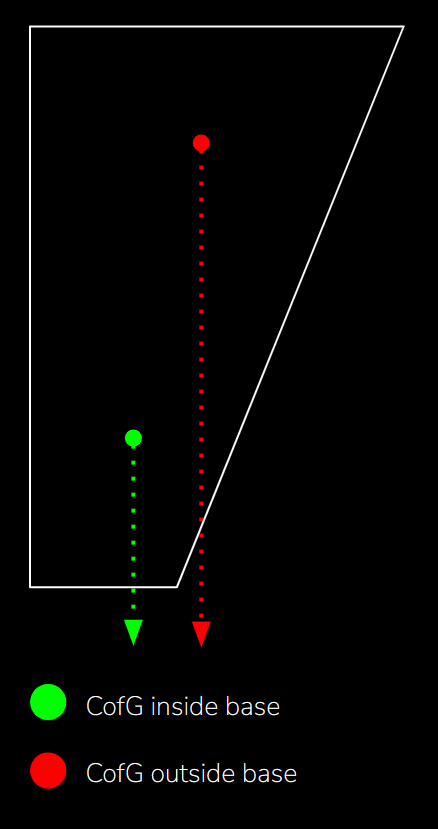
Center of Gravity
Center of gravity is a limitation whereby the center of gravity of the part at each layer must fall within the footprint of the base layer or it risks failing.
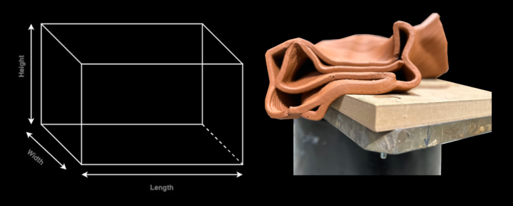
Length x Width x Height
There is a limit to how tall a part can be relative to the length and thickness of its walls, otherwise it risks collapsing.
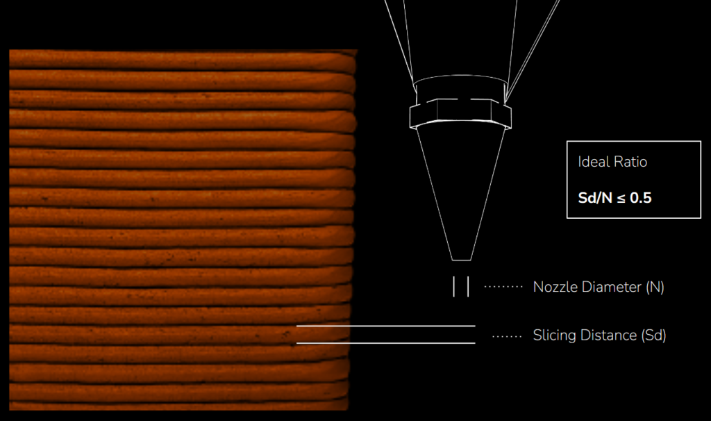
Nozzle Width vs Layer Height
There is an ideal ratio between nozzle width and layer height of about 0.5 for optimum extrusion and layer adhesion.
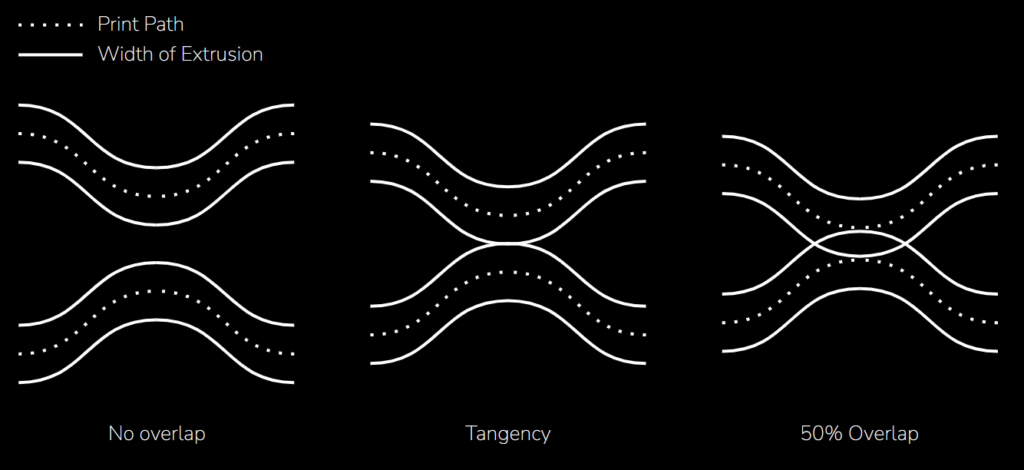
Layer Overlap
Side-by-side layers ought to overlap by about 50% for proper adhesion. Otherwise structural and surface finish problems may arise.
Infill
Adding infill to a part is a way to overcome some of the other constraints we’ve discussed, but the additional weight and printing and drying time ought to be considered.
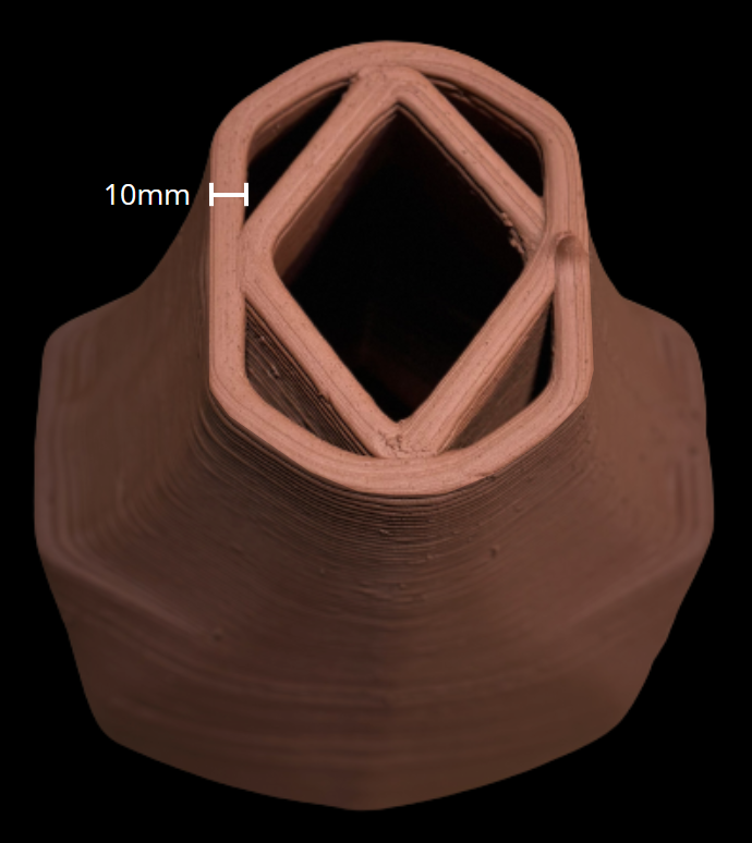
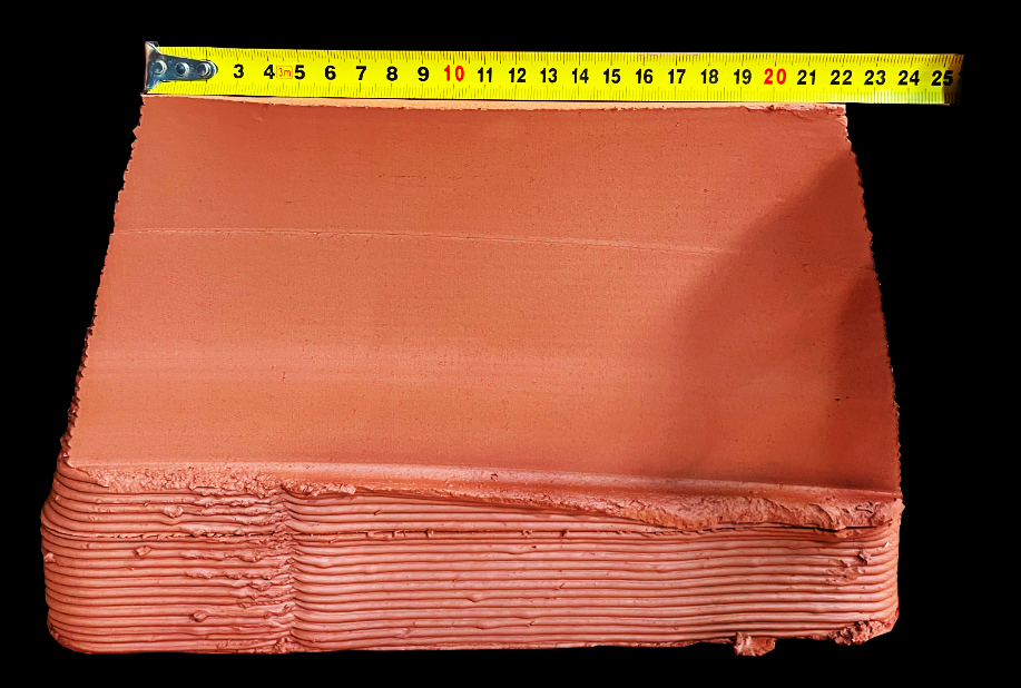
Wall Thickness
Wall thickness was significant in our work for three reasons: enhancing strength, facilitating cutting, and ensuring consistent drying and shrinkage by maintaining uniformity.
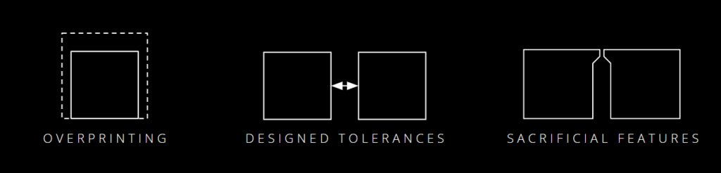
Deformation
The eternal challenge for ceramicists: shrinkage during drying and firing is typically greater at the top of our parts than the bottom due to adhesion and gravity. To overcome this, options include overprinting, design tolerances, and sacrificial alignment features.
Orientation
Clay printing is primarily done in a vertical manner, particularly with cartesian printers. However, the orientation of the part can be adjusted to accommodate desired surfaces.
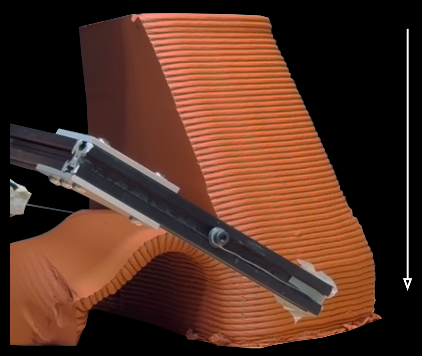
Cutting
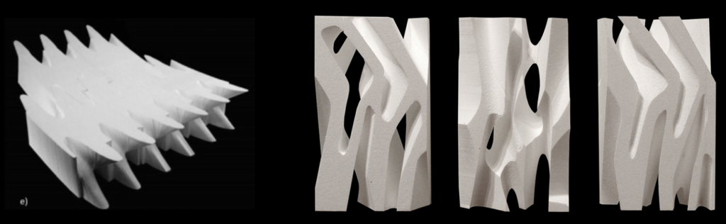
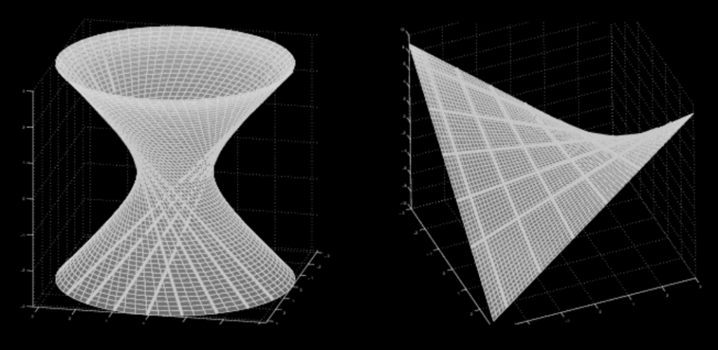
Wire cutting requires ruled surfaces, which offer a wide range of architectural design possibilities.
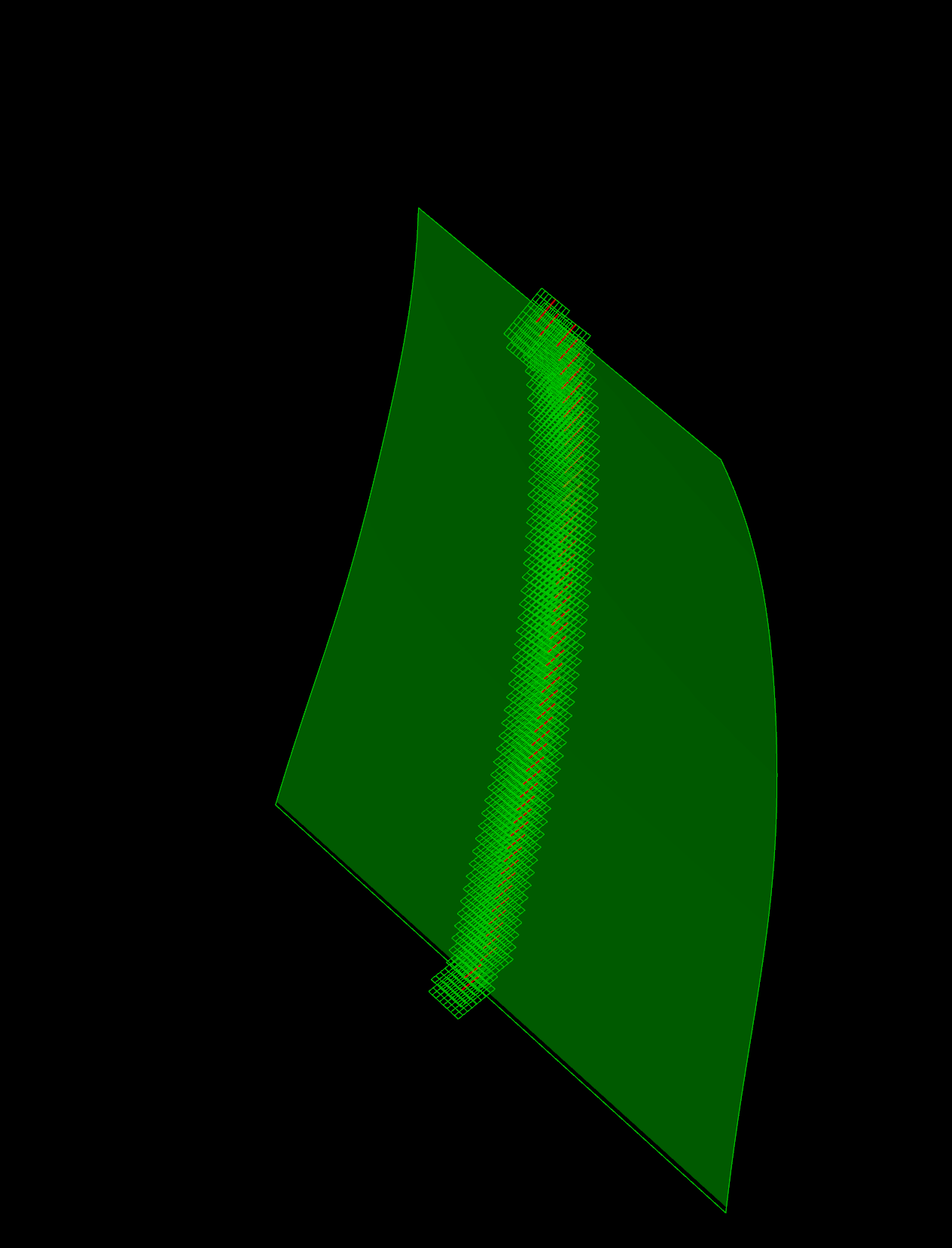
Collisions
Through simulation we monitor robotic paths to avoid collisions between the robot, end effector, and the printed part
Calibration Between Physical and Digital
Calibration and alignment were one of the greatest challenges to overcome during our process. Inaccuracies during calibration of the robot, shifting of the part on the print bed, or deformation during printing can all contribute to a misalignment of the wire with the intended cutting surface.
Deformation
Wire cutting exerts forces that can deform the part, particularly in the walls near the cutting surface, despite the narrow gauge of the wire.
Wall Thickness
Thicker wall thickness ensures even drying and compensates for imprecise wire cutter calibration.
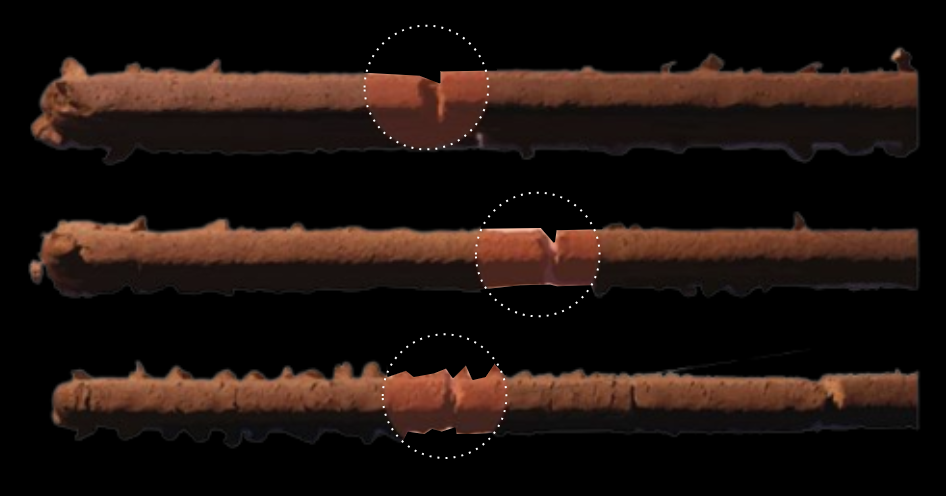
Wire Flexion
Wire flexion during cutting can cause striations on the cut surface, often due to insufficient wire tension or excessively dried clay.
Optimal Cutting Window
Clay consistency affects wire cutting. Soft clay results in deformation, while hard clay causes wire flexion or breakage. Optimal cutting time ranges from 1-4 hours for small parts (this for 3-5mm walls) and up to two days for larger parts (for 10-20mm walls), when wrapped in plastic.
Cut Direction
Collision avoidance restricts wire cutting angles, prohibiting fully vertical cuts. Cuts near the print table are also limited. We frequently added a sacrificial base to elevate the part, allowing for greater cutting freedom.
Wire/Surface Dimensions
The width of any specific cut surface has to be smaller than the wire being used.
Firing
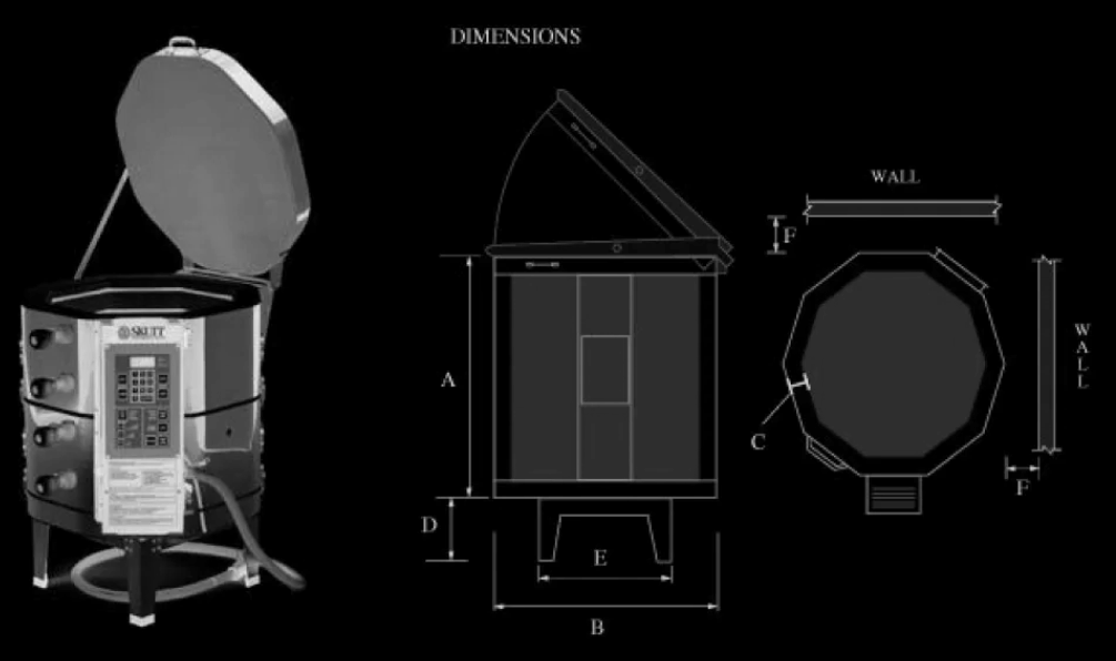
Kiln Size
Kiln size, which limits part size and therefore affects discretization.
Firing Schedul
Parts need to be fully dried and take about a day for firing
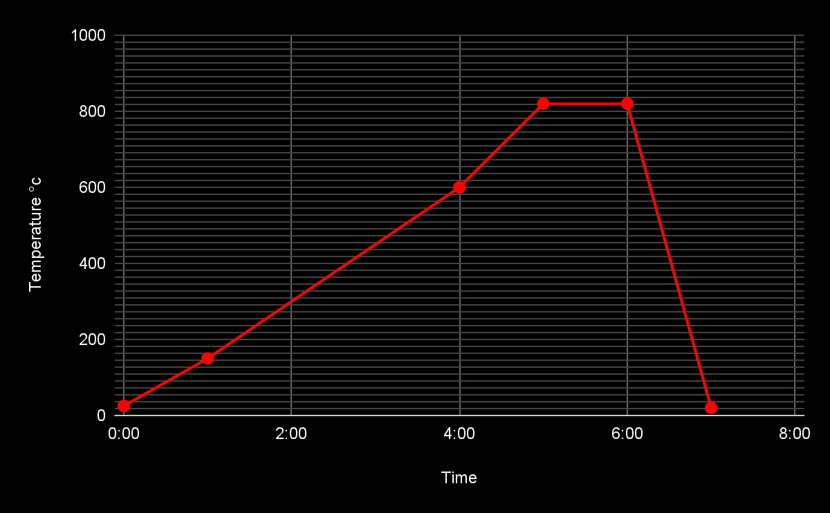
What Is the Difference Between a Gas and Electric Kiln
Shrinkage
Parts continue to shrink during firing.
Cracking
Cracking can occur for a number of reasons like moisture content, firing schedule and wall thickness.
These challenges multiply at scale.
Scan
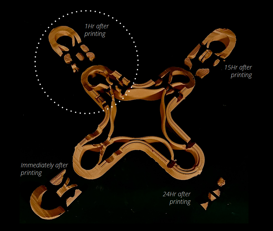
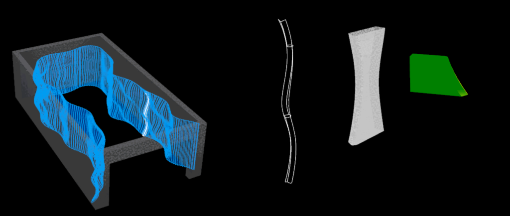
In larger parts the effects of gravity cause considerable shrinkage in the Z axis within a short time after printing. Since this contributes to changes in the cutting surface, we sought a solution to improve our cutting results.
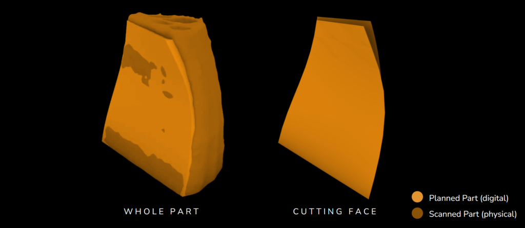
We introduced scanning into our workflow. We scan immediately before cutting, since the shape of the part changes over time. From the scan we extracted the new cutting face and use it to plan more accurate cutting paths for improved results
Scanned Print
Extract New Cutting Face
Align All Parts for Global Continuity
Plan New Cutting Planes
Plan Cutting Paths
CASE STUDY
As case study we produced different prototypes to explore the value of scanning and wire cutting in our hybrid workflow.
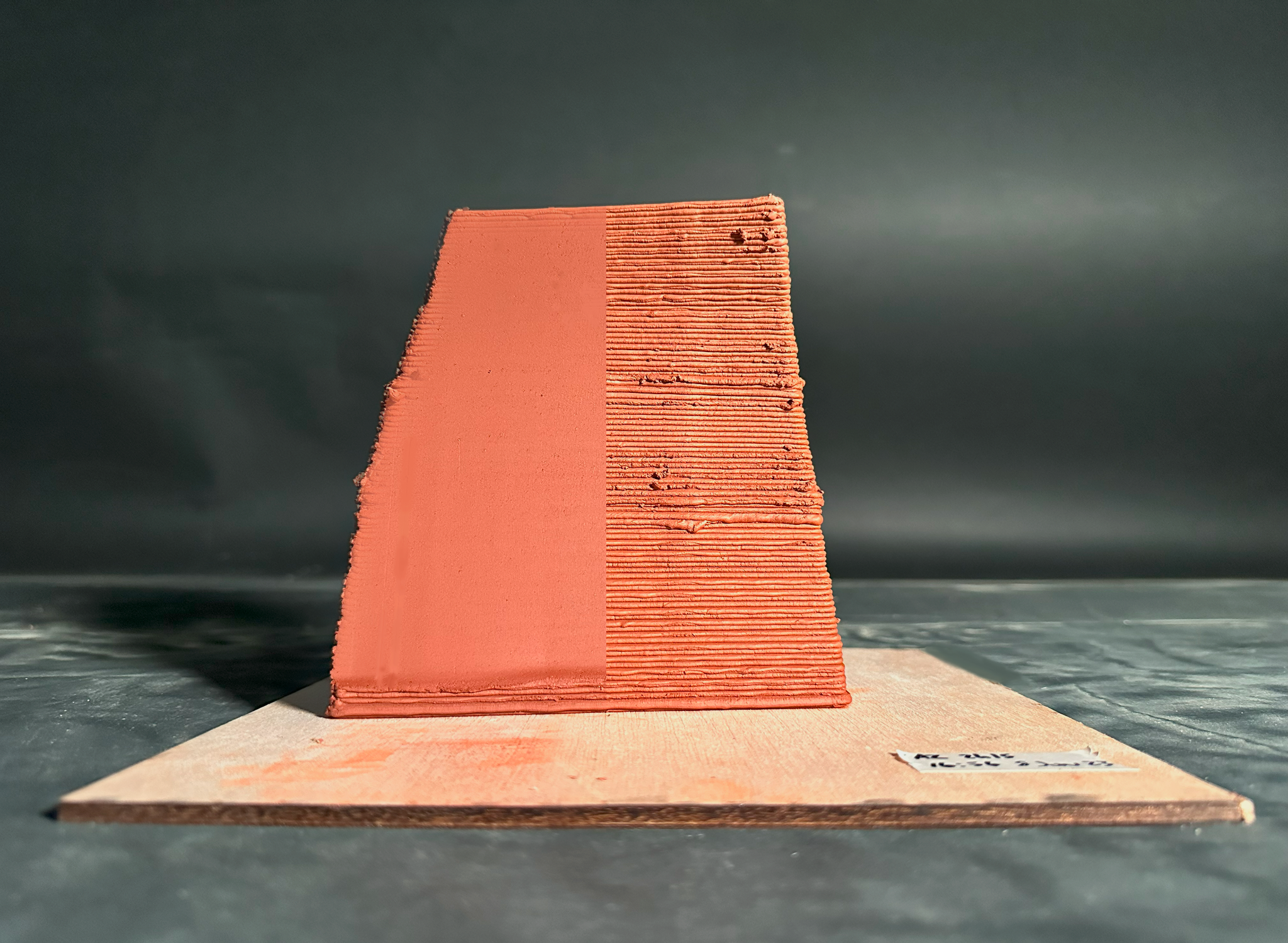
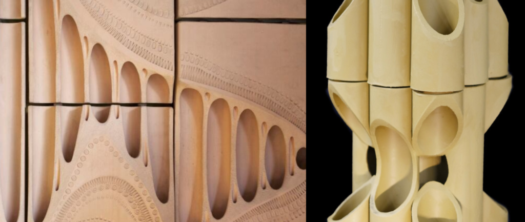
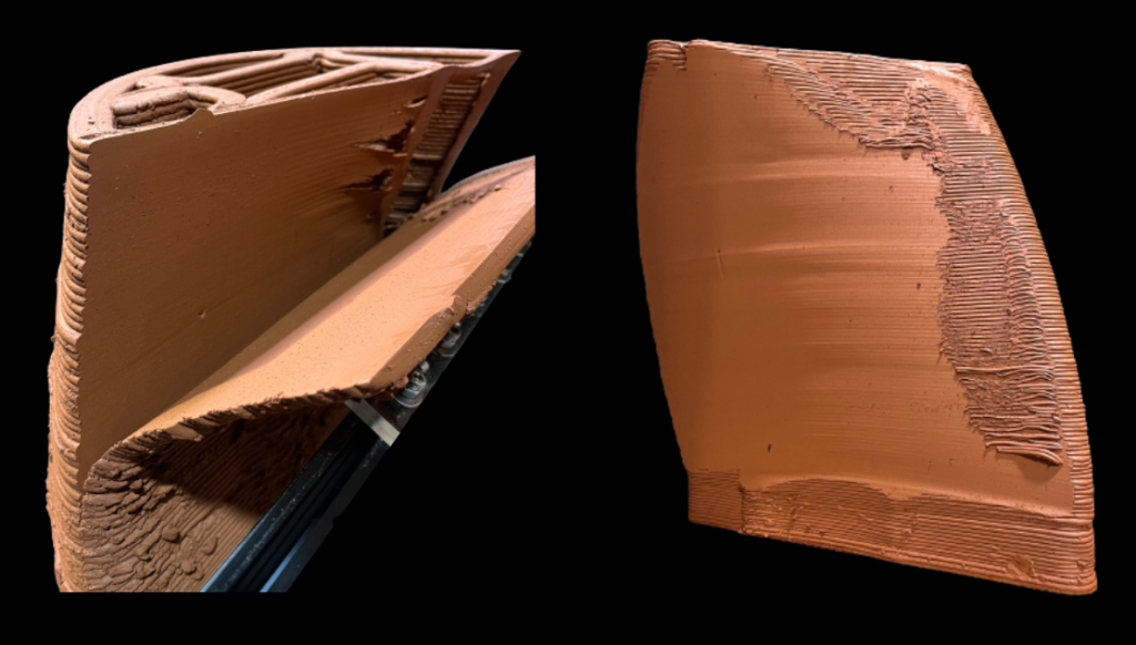
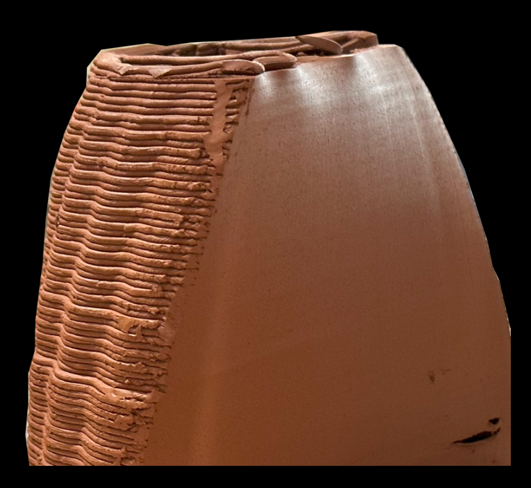
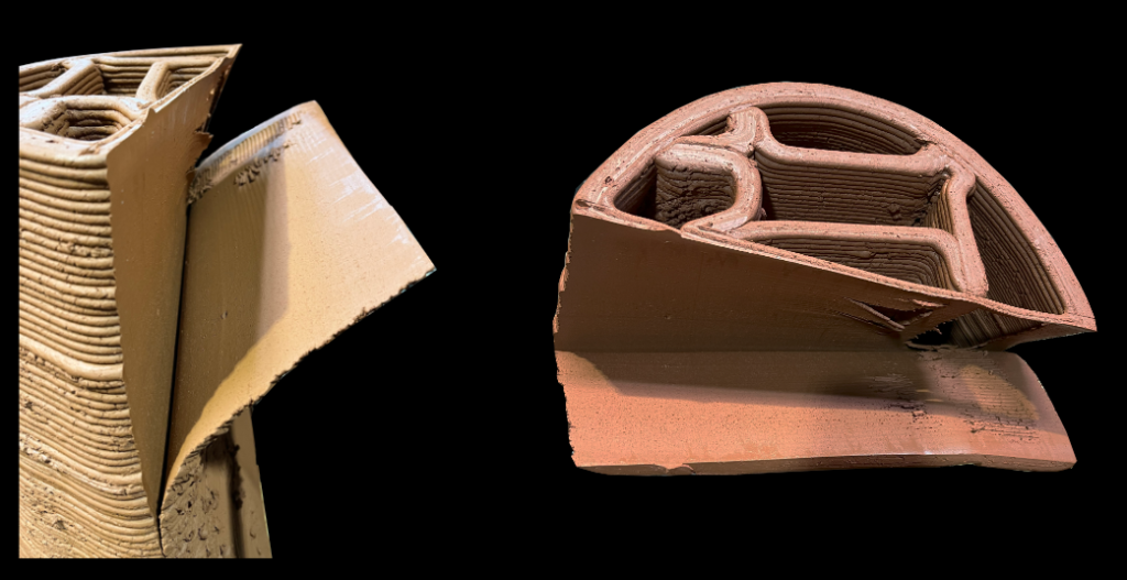
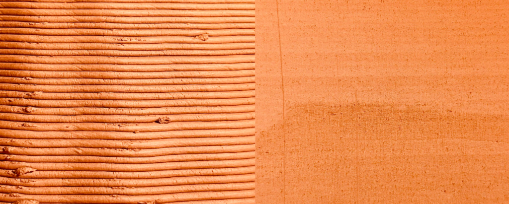
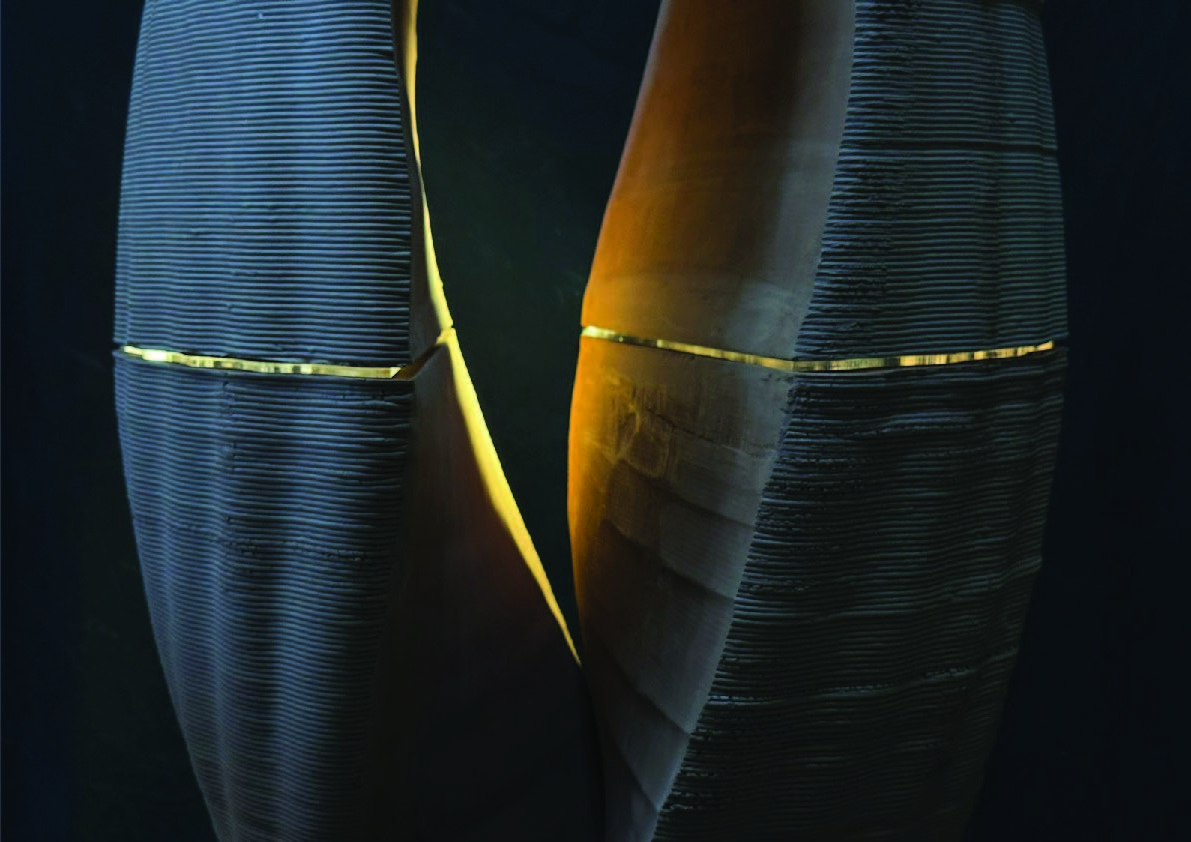
The purpose of our design was to showcase the contrast between a rough printed surface, and a smooth wire cut one.
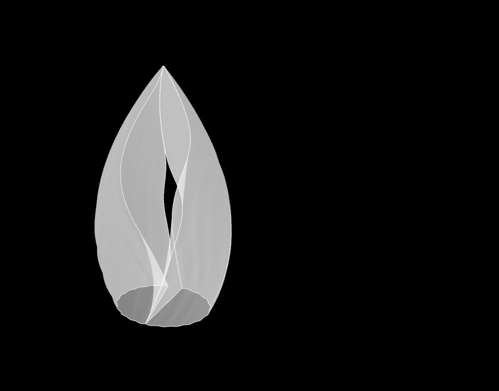
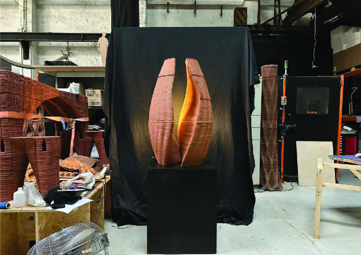
The form is reminiscent of a seed opening up to reveal new growth in the field of postprocessing. Or it could be thought of as an agate whose rough exterior is cut away to reveal an elegant interior.
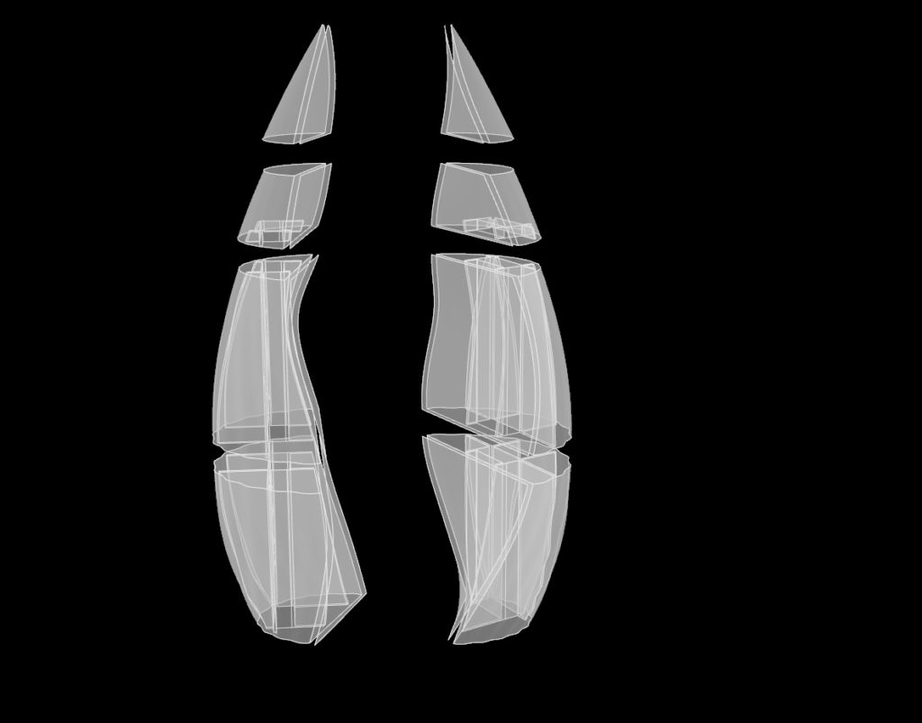
It is assembled with a substructure which uses a base and vertical rods. This substructure is being connected to the geometry through an infill. The infill design increases the strength of the cutting surfaces while the double thickness provides ease of wire cutting. The prototype is then discretized in 8 parts which size correspond to maximum kiln size available locally.
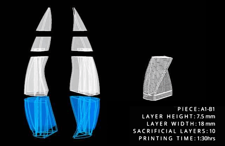
The dimensions of each piece correspond to the maximum height that can be printed in a single go. The print direction and cutting angles of the walls were optimized to respect the requirements for center of gravity and overhang angle. The cutting surfaces were designed so they could be cut with the wire remaining horizontal.
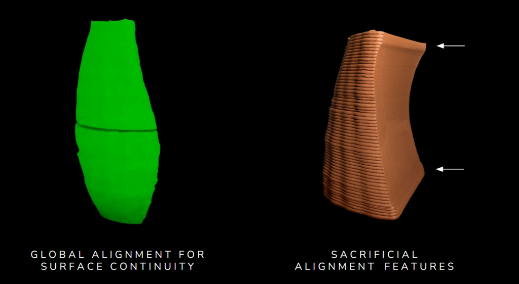
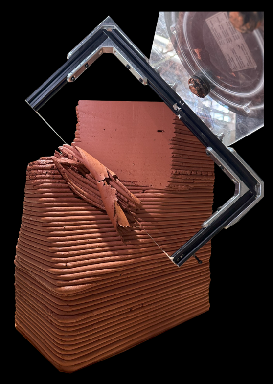
After having the printed pieces, we followed our scanning workflow for aligning the cutting faces across the entire geometry, and added some physical features to the parts aid in the alignment with minimal manual post processing.
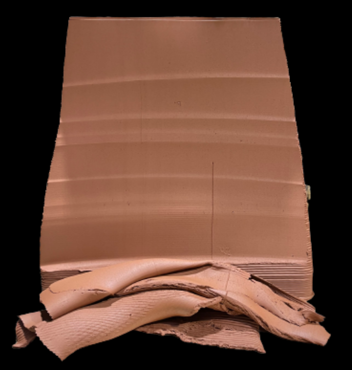
The benefits of wire cutting are more drastic on a larger scale, where the thicker extrusions make for an even rougher texture. During this process we experienced imperfection on the surfaces.
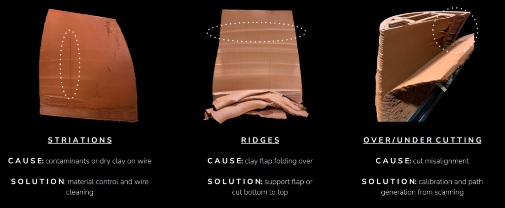
These imperfections can be fixed by postprocessing by hand, but it can also be avoided with process improvements.
FUTURE STEPS
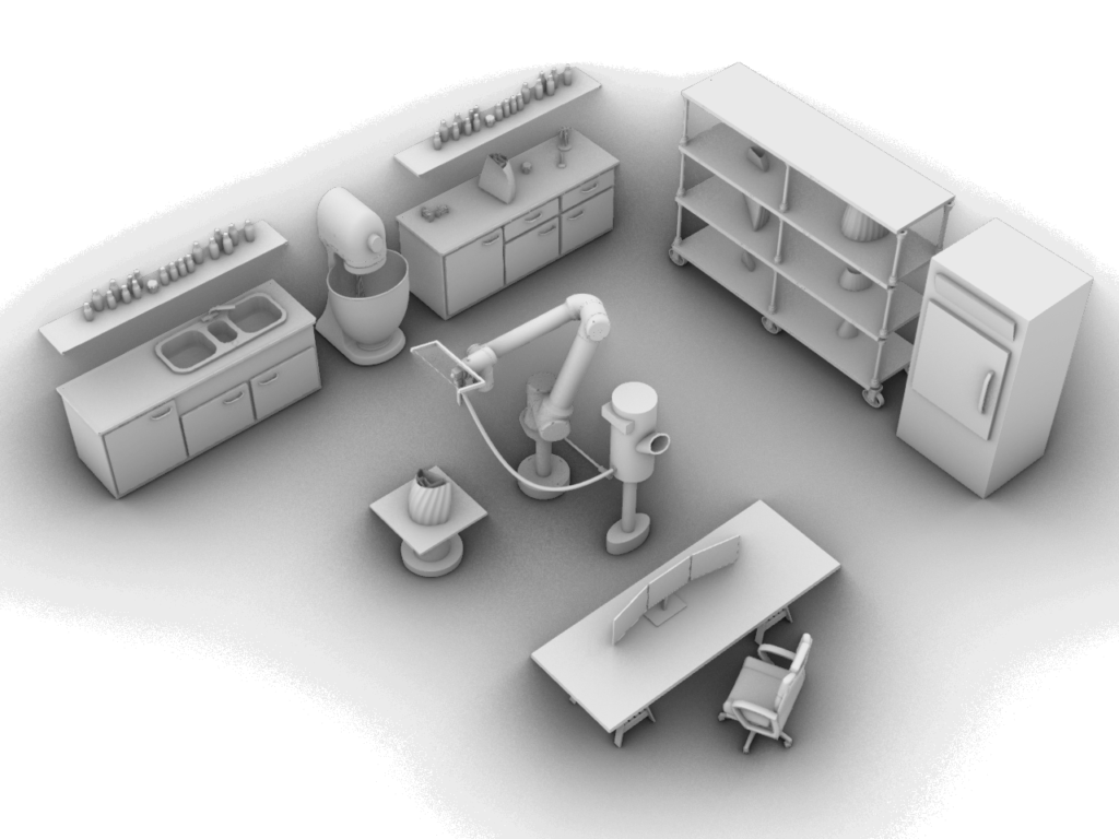
For our Manufacture vision. We reimagined the modern craftsman studio, where traditional craftsmanship meets cutting edge technology.
Here you can find a mixing station. Boasted with advanced machinery that will precisely measure and blend various types of clay. Also you can find a professional computer set up, an essential component of the modern craftsman toolkit.
At the heart of the studio, you will find the fabrication station. where the magic happens. Equipped with a UR20 collaborative robot, it is capable for hybrid manufacturing, combining 3D printing, scanning and wire cutting in one same end effector, El Toro. For larger prints and continuous production, a continuous clay feeding system is stationed nearby. There is also a drying station, for piece storage.
Next, we can find a postprocessing station, for any manual detailing. And finally we close the workflow with a kiln, the traditional companion for the ceramicist.
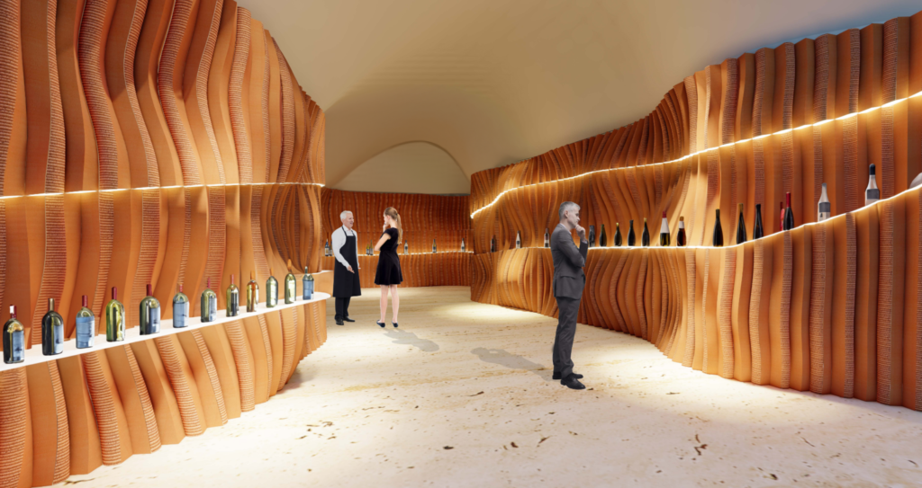
For architecture vision we see our workflow applied into a concept wine store, that seamlessly blends tradition and innovation. It offers a truly unique and immersive experience for wine enthusiasts. The concept is to showcase contrasting textures of bespoke 3D printed and post processed clay interior elements, which sets the stage for an extraordinary ambiance that harmonizes the rich history of wine with contemporary design.
Exploring the capabilities of our manufacturing workflow we discretized the interior façade into vertical blocks featuring a combination of ruled and doubly curved surfaces. All the component are stacked to generate the overall doubly curved surface functioning as a wine display shelf. Keeping in mind the manufacturing constraints each block has a vertical cutting plane which enables efficient path planning for robotic wire cutting. It has one smooth surface and a rough one showcasing the initial idea of contrast.
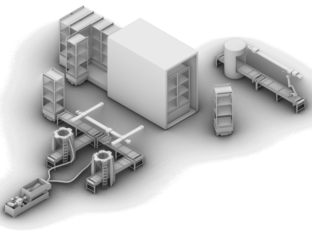
For mass production of components for our design vision, we scaled up our workflow envisioning an onsite micro factory setup. Here we can find an automated clay mixer with continuous feeding system. The clay is distributed without interruptions to maximize productivity.
The 3D printing station stands as the first link of the production system. Equipped with delta printers for better angular accuracy and a high printing speed. An automated conveyor transports the freshly printed pieces from the printer to a robotic scanning and wire cutting area. A dual end effector will meticulously refine each piece to perfection.
Once the pieces are printed and cut, the are transferred to an AGV. This Autonomous Guided Vehicles features an automated lifting and stacking system that arranges pieces into vertical columns. This AGV will move the stacked pieces to the drying station. The drying station itself boasts a moving kiln. The kiln area is divided into two parts, allowing for simultaneous drying and firing of multiple batches.
After the pieces are fired, another AGV will transport them to the final automated conveyor system, here the pieces undergo through a Quality control scanner which also collects data to train the shrinkage prediction AI model. Proceeding to packaging station, co-bots and humans will work together to wrap and package each piece for shipping.
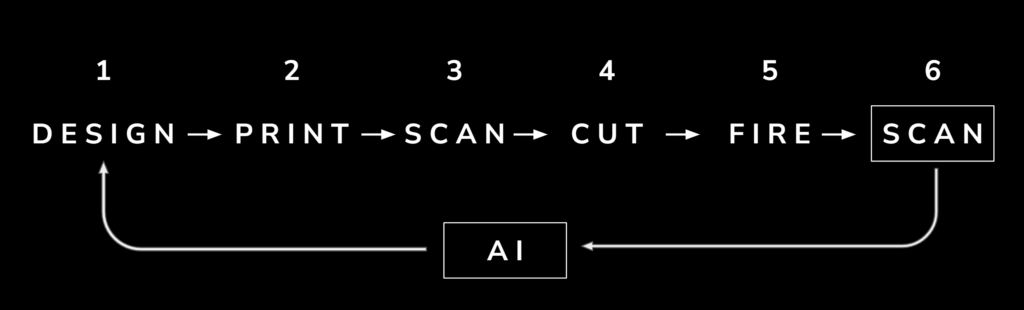
We propose a computational vision for our process. We propose scanning the final pieces again after they are fired to collect data to train an artificial neural network. A trained neural network would allow us to precisely scale the objects, feeding back into our design. We did some initial work on this during one of our seminars and the results were promising. We do this by extracting identifiable reference points from the freshly printed parts and final fired parts with scanning. We compare these points to compute a series of transformation vectors, and then use this dataset to train the neural network.
Once trained, the network will accept inputs such as ambient temperature, humidity, clay moisture content, and vertical position. It will then generate output vectors for predictive scaling. These output vectors are utilized to scale the design, and subsequently, the printing GCode is generated.
By incorporating this neural network into our workflow, it seamlessly complements each step, enhancing manufacturing performance for optimal results
