?The architectural system of the project is derived from two precedents; first, the Temple of Light in Canada, from Patkau Architects, which uses a series of identical ruled surfaces in a polar array. Next, the Mactan Cebu International Airport in the Philippines from Integrated Design Associates, which also uses identical ruled surface modules, in a linear array.
Precedent // Topology
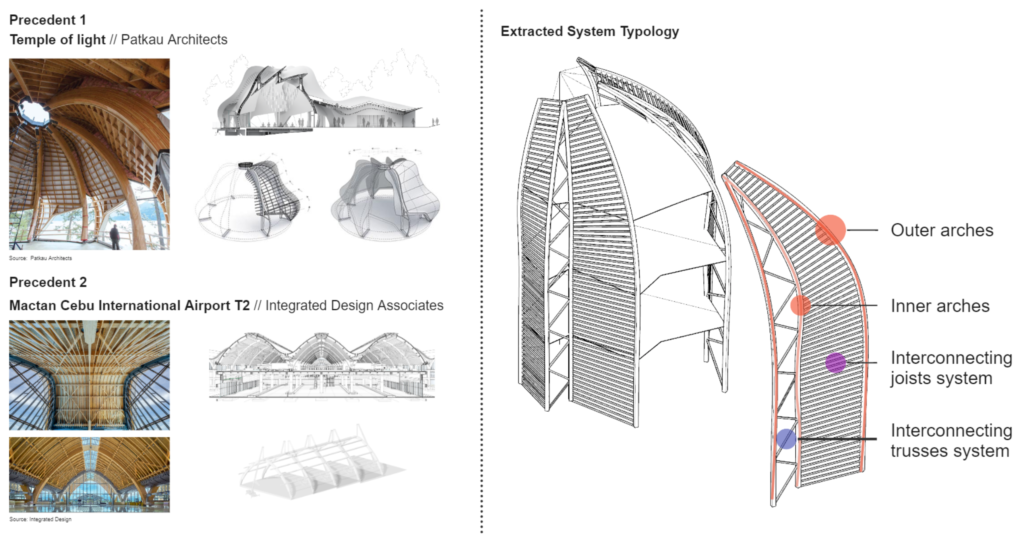
Although they apply the concept of ruled surfaces, these projects are limited to rigid forms, either a polar array that is familiar to a pavilion, or a linear path that does not respond well to context.
Informed by these two precedents, the extracted system still focuses around ruled surfaces, but adapting those surfaces to different applications and sizes. This is achieved by breaking the system down into its parametric elements: outer and inner arches joined by diagonal truss members with joists spanning between adjacent trusses, forming a ruled surface. These work together to new and unique programmable spaces.
Design Evolution

After exploring a variety of contextual applications of this typology which responded to user inputs, including closed loops, much like Patkau’s temple of light, as well as linear paths, systems we limited to one or 2 storeys, the system was expanded to a vertical application.
In the search for new forms of application, the possibility of incorporating our system as part of existing buildings was explored. The search was narrowed down to districts of single-use, midrise apartment blocks with massive concrete end walls and excessive parking space. This would host the necessary requirements for the typology to be implemented.
Context
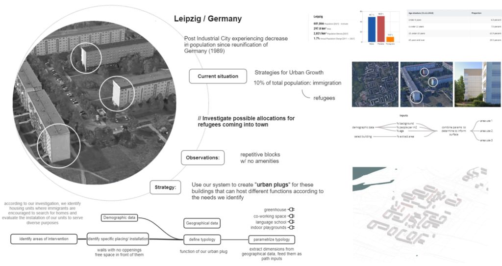
Leipzig, a city in Germany, was chosen as a location, being a post-industrial city where this typology is abundant. Urban shrinkage has been experienced by Leipzig after German reunification in 1989, and efforts to reverse this situation are currently being implemented by diverse strategies promoted by the local government. A demographic analysis revealed that 10% of the population is from a migratory background, and it also hosts 15% of Saxony’s refugee inflow.
During further investigation, it was discovered that refugees are encouraged to seek lodging in these types of buildings. The idea to use the system as “urban plugs” to host uses that complement the needs of refugees and migrants was conceived.
Both demographic and geographic data were extracted to inform the building. Demographic data would inform the uses and the necessary area per use, as well as the number of required floors. Geographic data would condition the final dimensions of the system, including height, width, and the paneling system, which is informed by environmental data.
System Parameterization
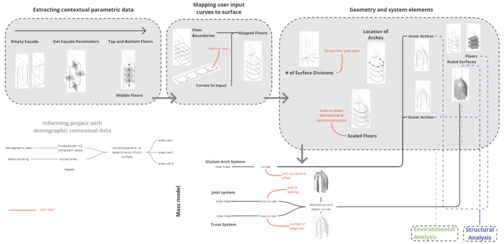
The parameterization of this system begins with user inputs, which are influenced by local population size, building sizes, and needs. This information guides the determination of the number of floors, programming, and floor areas. The façade serves as an input, with floor outlines being segmented based on the maximum joist span. These segments are then linked to form arches and offset to create secondary arches and trusses. During structural and environmental analyses, optimization is performed for truss depth (i.e. arch offset), joist spans, spacing, and truss count to accommodate soil loads, floor loads, and wind. Climate data is also considered to determine which panels should be vegetated and which should be glazed.
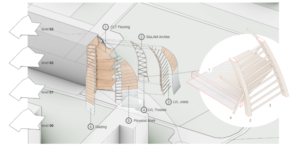
Materialization

The breakdown of materials for each element of this system is presented, highlighting their influence on design constraints. The primary system features glulam arches that gently curve to accommodate the necessary floor area for each floor, a design choice informed by structural optimization. To adhere to fabrication limitations, we ensure that the curvature never exceeds a 2.2m radius. Extending from the inner arch to the outer arch, both the horizontal joists and diagonal truss members consist of straight LVL timber elements. These elements are chosen for their ability to be more slender than glulam and are connected to the arches through steel hardware, with all dimensions restricted to never exceed 10m and preferably no more than 6m. The intermediate floors are constructed with CLT panels, reinforced by glulam floor beams that extend from the existing concrete wall to the arches. Finally, the shell enveloping our structure alternates between glazing and plywood, insulation, and a vertical green wall.
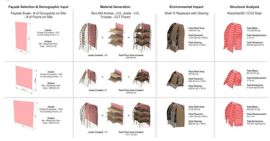
Following the materialization of the typology, further design options inspired by the context were explored. Three different scaled facade applications were initially examined on the site to understand how our design would adapt to generated materials, affected mass, and the structural efficiency of these materials. While it can be observed that our design is applicable to multiple façade scales, the smaller floor plates of the first two drastically outperform the larger façade when comparing material use and displacement to floor area, with the first two experiencing less displacement and emissions than the final.
Building on Site
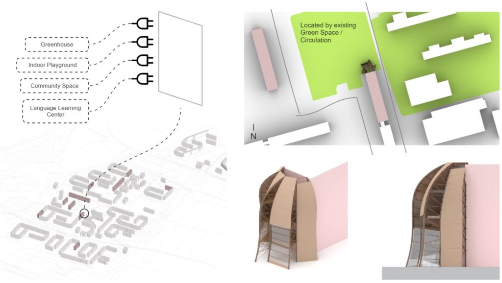
Considering a specific building on the site and upon exploration of a design matrix, the design was implemented at the chosen intervened location on the site, and this specific façade was selected for its proximity to existing green space and circulation. Not only was this form chosen based on our design matrix, but optimization was also performed using Wallacei X to minimize displacement and mass while maintaining a minimum usable floor area for occupants. Additionally, the most useful programmatic options that residents in the area are currently lacking were identified.
Material Traceback
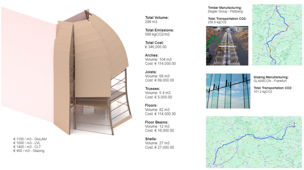
The wood industry is well-known in Germany. Manufacturers were found within the nearby areas. It was calculated that the material would travel 407 km per trip, and with a total volume of 300 cubic meters of material, 5 round trips would be needed, resulting in a total transportation carbon footprint of 350 kg of CO2. For the total volume constructed, emissions of an area of about 590 kg CO2/m2 for a total floor area of ~560 square meters were calculated. As for material cost, each part of the system was calculated using estimated prices based on the German market.
Architectural Drawings
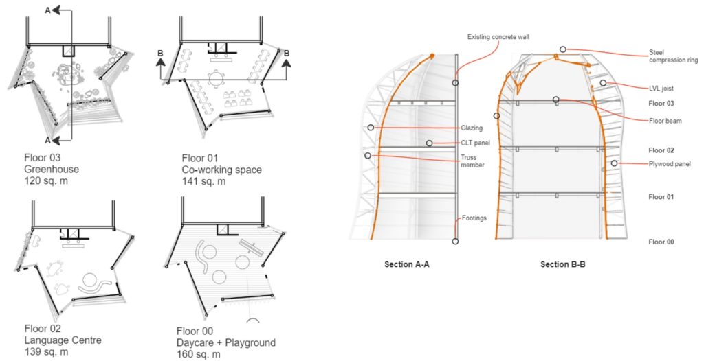
The floor plans are scaled to host different uses and are interconnected vertically. As observed, different applications on the left are designated for specific floors – from a greenhouse on the top floor, co-working spaces and a learning center on the middle floors, finally, with a daycare/playground on the ground floor. All uses are derived from previous analysis and data collection. The first and last arches are adjusted planarly to the facade, and then the rest of the system is utilized to cover the desired area, derived from user input. The given path is followed by all arches accordingly to the number of segments, allowing the input of floors of different sizes at different positions.
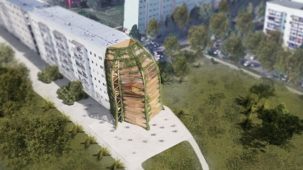
Renders